Page is loading ...

Service Manual
DEALER: Keep this manual. The
procedures in this manual MUST be
performed by a qualified technician.
For more information regarding
Invacare products, parts, and services,
please visit www.invacare.com
2G Tarsys
®
Powered
Seating System
2GT™- Tilt Only
2GR™- Recline Only
2GTR™- Tilt/Recline
on
TDX
®
Wheelchairs

USEFUL TERMS
2G Tarsys®Powered Seating System 2 Part No 1114842
WARNING
A QUALIFIED TECHNICIAN MUST PERFORM THE INITIAL SET UP
OF THIS SEATING SYSTEM. ALSO, A QUALIFIED TECHNICIAN
MUST PERFORM ALL PROCEDURES IN THIS SERVICE MANUAL.
DEALERS AND QUALIFIED TECHNICIANS: DO NOT SERVICE OR
OPERATE THIS EQUIPMENT WITHOUT FIRST READING AND
UNDERSTANDING (1) THE OWNER’S OPERATOR AND
MAINTENANCE MANUAL, (2) THE SERVICE MANUAL (IF
APPLICABLE) AND (3) THE SEATING SYSTEM’S MANUAL (IF
APPLICABLE). IF YOU ARE UNABLE TO UNDERSTAND THE
WARNINGS, CAUTIONS AND INSTRUCTIONS, CONTACT
INVACARE TECHNICAL SUPPORT BEFORE ATTEMPTING TO
SERVICE OR OPERATE THIS EQUIPMENT - OTHERWISE, INJURY
OR DAMAGE MAY RESULT.
USEFUL TERMS
The following acronyms are used throughout this manual:
\
REFERENCE DOCUMENTS
Refer to the table below for part numbers of additional documents which are referenced
in this manual.
ACRONYM DEFINITION
BPO Back Post Only option ordered on Tilt Only systems.
TRSS Tilt Recline Single Switch
SAC Single Actuator Control
TAC Two Actuator Control
TRCM Tilt Recline Control Module
VSR Vernier Shear Reduction
TDX BASE OWNER’S
MANUAL
TDX SERVICE MANUAL ELECTRONICS MANUAL
1114809 1114819 1114808 - MK
5
™EX™and MK
5
TT-EX
NOTE: Updated versions of this manual are available on www.invacare.com.

TABLE OF CONTENTS
Part No 1114842 3 2G Tarsys®Powered Seating System
TABLE OF CONTENTS
USEFUL TERMS ................................................................................. 2
REFERENCE DOCUMENTS ................................................................. 2
SPECIAL NOTES ................................................................................ 9
LABEL LOCATIONS ......................................................................... 11
TYPICAL PRODUCT PARAMETERS .................................................. 12
SECTION 1—GENERAL GUIDELINES ................................................. 14
Repair or Service Information ...............................................................................................................14
Operation Information............................................................................................................................14
Grounding Instructions ...........................................................................................................................16
SECTION 2—SAFETY/HANDLING OF WHEELCHAIRS ......................... 17
Pinch Points................................................................................................................................................17
SECTION 3—EMI INFORMATION ..................................................... 18
SECTION 4—SAFETY INSPECTION/TROUBLESHOOTING .................... 20
Safety Inspection Checklist.....................................................................................................................20
Post-Service Inspection Checklist.........................................................................................................21
Troubleshooting........................................................................................................................................22
SECTION 5—INTERFACE HARDWARE .............................................. 24
Repositioning the Seat.............................................................................................................................24
About Repositioning the Seat ...........................................................................................................24
Repositioning the Seat on 2GR Systems ........................................................................................24
Repositioning the Seat for 2GT and 2GTR Systems....................................................................33
Removing/Installing the Rear Pivot Assembly ....................................................................................41
Tilt Only and Tilt/Recline Systems...................................................................................................41
Recline Only Systems..........................................................................................................................44
Removing/Installing the Front Pivot Assembly...................................................................................45
Removing ...............................................................................................................................................45
Installing..................................................................................................................................................45
Removing/Installing the Linear Guides.................................................................................................46
Removing/Installing the Seat Brackets .................................................................................................48
Tilt Only and Tilt/Recline Systems...................................................................................................48
Recline Only Systems..........................................................................................................................51
Removing/Installing the Lower Interface Brackets............................................................................52
Removing ...............................................................................................................................................52
Installing..................................................................................................................................................52
SECTION 6—SEAT ADJUSTMENTS .................................................... 54
Replacing Seat Positioning Strap ...........................................................................................................54

TABLE OF CONTENTS
2G Tarsys®Powered Seating System 4 Part No 1114842
TABLE OF CONTENTS
Removing/Installing Seat Pan..................................................................................................................54
Removing ...............................................................................................................................................54
Installing..................................................................................................................................................54
Adjusting Seat Width...............................................................................................................................55
Preparing to Adjust Seat Width .......................................................................................................55
Tilt-Only Seating Systems...................................................................................................................56
Recline Only or Tilt/Recline Seating Systems................................................................................57
Adjusting Seat Depth ...............................................................................................................................58
About Seat Depth................................................................................................................................58
Adjusting Seat Depth...........................................................................................................................60
Adjusting Seat Angle ................................................................................................................................61
Tilt-Only and Tilt/Recline Seating Systems ....................................................................................61
Recline-Only Seating Systems ...........................................................................................................61
Removing/Installing Side Frames ...........................................................................................................66
Removing Side Frames........................................................................................................................66
Preparing Side Frames for Replacement.........................................................................................67
Installing Side Frames ..........................................................................................................................69
Removing/Installing Center Seat Frame ..............................................................................................70
Removing Center Seat Frame ...........................................................................................................70
Installing Center Seat Frame .............................................................................................................71
Adjusting/Replacing Telescoping Front Rigging Supports................................................................73
Adjusting/Replacing Leg Support Tubes ..............................................................................................73
Adjusting Leg Support Tubes ............................................................................................................73
Replacing Leg Support Tubes............................................................................................................74
Removing/Installing the Seat...................................................................................................................75
Removing ...............................................................................................................................................75
Installing..................................................................................................................................................77
SECTION 7—BACK ADJUSTMENTS .................................................. 80
Adjusting Back Width..............................................................................................................................80
Adjusting Back Angle ...............................................................................................................................80
Removing/Installing the Curved Links..................................................................................................82
Tilt Only Systems.................................................................................................................................82
Recline Only and Tilt/Recline Systems............................................................................................83
Removing/Installing Back Pan .................................................................................................................85
Removing ...............................................................................................................................................85
Installing..................................................................................................................................................85
Removing/Installing Spreader Bar .........................................................................................................87
Slotted Back Canes..............................................................................................................................87
Round Back Canes...............................................................................................................................88

TABLE OF CONTENTS
Part No 1114842 5 2G Tarsys®Powered Seating System
TABLE OF CONTENTS
Removing/Installing Back Canes ............................................................................................................89
Removing ...............................................................................................................................................89
Installing..................................................................................................................................................89
Removing/Installing Back Slide Assembly ............................................................................................90
Removing ...............................................................................................................................................90
Installing..................................................................................................................................................90
Removing/Installing Back Assembly ......................................................................................................91
Removing ...............................................................................................................................................91
Installing..................................................................................................................................................91
Adjusting the Back Height ......................................................................................................................92
Overview ...............................................................................................................................................92
Removing/Installing Arm Pivots.............................................................................................................93
Removing ...............................................................................................................................................93
Installing..................................................................................................................................................93
Removing/Installing/Adjusting Chest Positioning Strap....................................................................94
Removing ...............................................................................................................................................94
Installing..................................................................................................................................................94
Adjusting Height...................................................................................................................................94
Installing/Removing/Adjusting Lateral Supports.................................................................................95
Slotted Canes........................................................................................................................................95
Round Canes.........................................................................................................................................97
SECTION 8—SHROUDS .................................................................... 99
Shroud Overview .....................................................................................................................................99
Removing/Installing VSR Shroud ........................................................................................................ 100
Removing/Installing Side Shrouds....................................................................................................... 100
Removing/Installing Rear Seat Shroud .............................................................................................. 101
Removing/Installing Rear Shroud ....................................................................................................... 102
Removing/Installing Lower Seat Shroud........................................................................................... 102
SECTION 9—POWER ELEVATING LEGRESTS .................................... 104
Installing/Removing the Power Elevating Legrests ......................................................................... 104
Installing the Power Elevating Legrests ........................................................................................ 105
Removing the Power Elevating Legrests...................................................................................... 105
Adjusting the Power Elevating Legrests ........................................................................................... 106
Adjusting the Footplate ................................................................................................................... 106
Adjusting the Calf Pad...................................................................................................................... 108
Adjusting the Length of Power Legrest ....................................................................................... 110
Removing/Installing the Power Elevating Legrest Harness .......................................................... 110
Removing ............................................................................................................................................ 110
Installing............................................................................................................................................... 110

TABLE OF CONTENTS
2G Tarsys®Powered Seating System 6 Part No 1114842
TABLE OF CONTENTS
Removing/Installing the Power Elevating Legrest Actuator......................................................... 112
Removing ............................................................................................................................................ 112
Installing............................................................................................................................................... 112
SECTION 10—ARMS ...................................................................... 114
Removing/Installing Reclining Armrests ........................................................................................... 114
Removing Armrests.......................................................................................................................... 114
Installing Armrests ............................................................................................................................ 114
Adjusting Armrest Height.................................................................................................................... 115
Installing/Removing Flip-Back Armrests ........................................................................................... 116
Installing............................................................................................................................................... 116
Removing ............................................................................................................................................ 117
Adjusting Flip-Back Armrest Height.................................................................................................. 118
SECTION 11—CENTER MOUNT FOOTRESTS ................................... 119
Removing/Installing the Center Mount Footrest ........................................................................... 119
Removing ............................................................................................................................................ 119
Installing............................................................................................................................................... 119
Adjusting the Height of the Center Mount Footrest.................................................................... 120
Adjusting the Angle of the Center Mount Footrest...................................................................... 121
Adjusting the Center Mount Footplate Angle ................................................................................ 121
After 2/14/07...................................................................................................................................... 121
Before 2/15/07................................................................................................................................... 122
Adjusting the Tension of the Center Mount Footplate................................................................ 122
Removing/Installing the Release Lever Assembly........................................................................... 122
SECTION 12—HEADREST .............................................................. 124
Removing/Installing/Adjusting Headrest ........................................................................................... 124
Removing ............................................................................................................................................ 124
Installing............................................................................................................................................... 124
Adjusting Headrest Height.............................................................................................................. 125
Adjusting Headrest Depth/Direction ........................................................................................... 125
Replacing Headrest ............................................................................................................................... 125
SECTION 13—TILT AND RECLINE .................................................. 126
A Note About Drive Lock-Out ......................................................................................................... 126
Operating Powered Seating Systems ................................................................................................ 127
Single Function Toggle Switch (TRSS).......................................................................................... 128
Optional Four-Way Toggle Switch ............................................................................................... 129
Vernier Shear Reduction (2G Tarsys Systems Only) ............................................................... 130
Removing/Installing the Tilt Actuator ............................................................................................... 131
Removing ............................................................................................................................................ 131
Installing............................................................................................................................................... 131
Removing/Installing the VSR Actuator.............................................................................................. 132

TABLE OF CONTENTS
Part No 1114842 7 2G Tarsys®Powered Seating System
TABLE OF CONTENTS
Removing ............................................................................................................................................ 132
Installing............................................................................................................................................... 133
Removing/Installing the Recline Actuator........................................................................................ 133
Removing ............................................................................................................................................ 133
Installing............................................................................................................................................... 133
Testing the Actuators........................................................................................................................... 134
Removing/Installing Recline Links ...................................................................................................... 135
Removing ............................................................................................................................................ 135
Installing............................................................................................................................................... 135
Removing/Installing Tilt Links.............................................................................................................. 137
Removing ............................................................................................................................................ 137
Installing............................................................................................................................................... 137
SECTION 14—ELECTRONICS .......................................................... 139
Removing/Installing the Single Actuator Control (SAC) .............................................................. 139
Removing ............................................................................................................................................ 139
Installing............................................................................................................................................... 140
Removing/Installing the TAC or TRCM ........................................................................................... 141
Removing the TAC/TRCM Controller Bracket......................................................................... 141
Installing the TAC/TRCM Controller Bracket........................................................................... 142
Removing the TAC/TRCM from the Controller Bracket ....................................................... 144
Installing the TAC/TRCM onto the Controller Bracket.......................................................... 144
Programming the TAC ......................................................................................................................... 146
Calibrating the Tilt Potentiometer for a TAC................................................................................ 146
Replacing the Tilt Recline Single Switch (TRSS) ............................................................................. 148
Removing/Installing Joystick(s)............................................................................................................ 149
Removing ............................................................................................................................................ 149
Installing............................................................................................................................................... 149
Drive Lock-Out...................................................................................................................................... 150
Removing/Installing the Tilt Potentiometer..................................................................................... 150
Removing ............................................................................................................................................ 150
Installing............................................................................................................................................... 151
Adjusting the Tilt Potentiometer....................................................................................................... 152
Adjusting a Tilt Potentiometer Used With a TRSS................................................................... 152
Adjusting Tilt Potentiometer Used With a TRCM, TAC or SAC......................................... 153
Adjusting Recline Potentiometer....................................................................................................... 154
Removing/Installing the Recline Potentiometer.............................................................................. 155
Removing ............................................................................................................................................ 155
Installing............................................................................................................................................... 155

TABLE OF CONTENTS
2G Tarsys®Powered Seating System 8 Part No 1114842
TABLE OF CONTENTS
SECTION 15—WIRING AND CABLES .............................................. 157
Securing the Cables............................................................................................................................... 157
TAC Cables........................................................................................................................................ 157
Tilt Actuator Cable........................................................................................................................... 158
Tilt Potentiometer Cable ................................................................................................................ 158
Power Elevating Legrest, Recline Actuator and Recline Potentiometer Cables................ 159
4-Way Switch, TRCM and/or TAC Cables................................................................................. 161
Joystick, SAC or TRSS Cables........................................................................................................ 163
All Cables (Final Steps) .................................................................................................................... 163
Wiring Schematics................................................................................................................................. 164
TRSS..................................................................................................................................................... 164
SAC ...................................................................................................................................................... 165
TRCM/TAC........................................................................................................................................ 166
LIMITED WARRANTY ................................................................... 168

SPECIAL NOTES
Part No 1114842 9 2G Tarsys®Powered Seating System
SPECIAL NOTES
Signal words are used in this manual and apply to hazards or unsafe practices which
could result in personal injury or property damage. Refer to the table below for
definitions of the signal words.
NOTICE
THE INFORMATION CONTAINED IN THIS DOCUMENT IS SUBJECT TO
CHANGE WITHOUT NOTICE.
WHEELCHAIR TIE-DOWN RESTRAINTS AND SEAT RESTRAINTS (TRBKTS)
TRBKTS includes four factory-installed wheelchair transport brackets. TRBKTS has
not been crash-tested in accordance with WC 19. Use these transport brackets only
to secure an unoccupied wheelchair during transport.
As of this date, the Department of Transportation has not approved any tie-down
systems for transportation of a user while in a wheelchair, in a moving vehicle of any
type. It is Invacare’s position that users of wheelchairs should be transferred into
appropriate seating in vehicles for transportation and use be made of the restraints
made available by the auto industry. Invacare cannot and does not recommend any
wheelchair transportation systems.
TRBKTS WARNINGS
Only use the transport brackets included with TRBKTS for the purposes described
in the wheelchair base owner’s manual.
WARNING
Invacare products are specifically designed and manufactured for use in conjunction
with Invacare accessories. Accessories designed by other manufacturers have not
been tested by Invacare and are not recommended for use with Invacare products.
The seat positioning strap is a positioning belt ONLY. It is not designed for use as a
safety device withstanding high stress loads such as auto or aircraft safety belts. If
signs of wear appear, belt MUST be replaced immediately.
Wheelchairs should be examined during maintenance for signs of corrosion (water
exposure, incontinence, etc.). Electrical components damaged by corrosion should
be replaced IMMEDIATELY.
SIGNAL WORD MEANING
DANGER
Danger indicates an imminently hazardous situation which, if not avoided,
will result in death or serious injury.
WARNING
Warning indicates a potentially hazardous situation which, if not avoided,
could result in death or serious injury.
CAUTION
Caution indicates a potentially hazardous situation which, if not avoided,
may result in property damage.

SPECIAL NOTES
2G Tarsys®Powered Seating System 10 Part No 1114842
WARNING
Wheelchairs that are used by incontinent users and/or are frequently exposed to
water may require replacement of electrical components more frequently.
Refer to wheelchair base service manual for additional safety and operation
information.


TYPICAL PRODUCT PARAMETERS
2G Tarsys®Powered Seating System 12 Part No 1114842
TYPICAL PRODUCT PARAMETERS
2G TARSYS SEATING SYSTEM
SEAT WIDTH RANGE: 16 - 22 inches in 1-inch increments
SEAT DEPTH RANGE: 16 - 22 inches in 1-inch increments
BACK HEIGHT RANGE
TILT/RECLINE:
RECLINE:
TILT:
20 - 26 inches in 1-inch increments
20 - 26 inches in 1-inch increments
20 - 25 inches in 1-inch increments
BACK ANGLE RANGE
TILT: 90° - 115° in 5° increments
TILT RANGE
TILT AND TILT/RECLINE
0° Seat Angle:
5° Seat Angle:
0° - 45° ± 3°
5° - 50° ± 3°
RECLINE RANGE (MEASURED RELATIVE
TO THE GROUND)
RECLINE
0° Seat Angle:
5° Seat Angle:
10° Seat Angle:
15° Seat Angle:
TILT/RECLINE
0° Seat Angle:
5° Seat Angle:
90° - 175° ± 3°
95° - 175° ± 3°
100° - 175° ± 3°
105° - 175° ± 3°
90° - 175° ± 3°
95° - 175° ± 3°
SEAT-TO-FLOOR
0° SEAT ANGLE:
5° SEAT ANGLE:
18.5 inches ± .25 inches
20 inches ± .25 inches
*OVERALL WIDTH
WITH 4-WAY SWITCH: 28.9 inches
*OVERALL HEIGHT
(WITHOUT HEADREST): 40.9 inches
*OVERALL LENGTH
WITH CENTER MOUNT FOOTREST AT 90°:
WITHOUT FRONT RIGGINGS, FULL LENGTH
ARM, MPJ™ JOYSTICK:
41.5 inches
39.3 inches
ARMRESTS
TILT:
RECLINE AND TILT/RECLINE:
Flip Back, Adjustable Height (9 - 13 inches) - Desk or Full
Length
Adjustable Height (11 - 16 inches) - Desk or Full Length
LEGRESTS: Swingaway Footrests, Center Mount Footrests, Mechanical
Elevating, Genius Legrests, or Power Elevating Legrests
HEADRESTS: Curved, Contoured, Small or Large
*NOTE: 20 inch deep x 20 inch wide with 24 inch high back.
NOTE: All dimensions are ± .50 inches unless otherwise indicated.
NOTE: All parameters apply to Tilt only, Recline only and Tilt/Recline systems except where
specified. All parameters are approximate.

TYPICAL PRODUCT PARAMETERS
Part No 1114842 13 2G Tarsys®Powered Seating System
WARNING
If the seating system is mounted onto a power wheelchair that has a weight
limitation greater than that of the seating system, the weight limitation is
maintained at the seating system’s limitation. (Example: If the wheelchair is a TDX
5 with a 400 lb. weight limitation, the seating system still has a weight limitation of
350 lbs.).
WEIGHT LIMITATION:
ALL SEATING SYSTEMS WITHOUT HEAVY
DUTY OPTION:
TILT ONLY, RECLINE ONLY OR TILT/RECLINE
SYSTEMS WITH HEAVY DUTY OPTION:
ALL SEATING SYSTEMS WITH VENT TRAY:
250 lbs
350 lbs
Subtract 50 lbs from the seating system weight limitations
(200 and 300 lbs respectively)
BATTERY REQUIREMENTS: Refer to Batteries
on page 137.
ELECTRONICS
SEATING SYSTEM CONTROL MODULES:
WHEELCHAIR CONTROL MODULE:
JOYSTICKS:
TRCM, SAC, TAC, TRSS
MK
5
EX or MK
5
TT-EX
MPJ™or DPJ™
2G TARSYS SEATING SYSTEM
*NOTE: 20 inch deep x 20 inch wide with 24 inch high back.
NOTE: All dimensions are ± .50 inches unless otherwise indicated.
NOTE: All parameters apply to Tilt only, Recline only and Tilt/Recline systems except where
specified. All parameters are approximate.

SECTION 1—GENERAL GUIDELINES
2G Tarsys®Powered Seating System 14 Part No 1114842
SECTION 1—GENERAL GUIDELINES
WARNING
SECTION 1 - GENERAL GUIDELINES contains important information for the safe
operation and use of this product. DO NOT use this product or any available
optional equipment without first completely reading and understanding these
instructions and any additional instructional material such as Owner’s Manuals,
Service Manuals or Instruction Sheets supplied with this product or optional
equipment. If you are unable to understand the Warnings, Cautions or Instructions,
contact a healthcare professional, dealer or technical personnel before attempting
to use this equipment - otherwise, injury or damage may occur.
Repair or Service Information
Except for programming, DO NOT service or adjust the wheelchair while occupied,
unless otherwise noted.
After ANY adjustments, repair or service and before use, make sure all attaching
hardware is tightened securely - otherwise injury or damage may occur.
Before adjusting, repairing or servicing the seating system, ALWAYS turn the wheelchair
power OFF, otherwise, injury or damage may result.
Pinch points exist between seat and base frames. Use caution, otherwise injury may occur.
Cables MUST be routed and secured properly to ensure that the cables DO NOT become
entangled and damaged during normal operation of seating system.
Cables MUST be secured to the wheelchair frame and/or base with tie-wraps after
servicing is complete. Failure to follow the warnings and instructions listed within this
manual could result in injury to the users, attendants and/or bystanders and/or damage
to the wheelchair.
Cables MUST be secured so there are no loops of excess cable extending away from the
wheelchair. Bundle all excess cable together and secure with a tie-wrap. It may also be
necessary to secure these bundles to the frame and/or base.
ALWAYS test all wheelchair functions after securing the cables to be sure cables DO NOT
get pinched, crushed, or strained during operation of the wheelchair.
Operation Information
Invacare products are specifically designed and manufactured for use in conjunction with
Invacare accessories. Accessories designed by other manufacturers have not been tested
by Invacare and are not recommended for use with Invacare products.
DO NOT attempt to lift the wheelchair by any removable (detachable) parts. Lifting by
means of any removable (detachable) parts of a wheelchair may result in injury to the user
or damage to the wheelchair.

SECTION 1—GENERAL GUIDELINES
Part No 1114842 15 2G Tarsys®Powered Seating System
Performance adjustments should only be made by professionals of the healthcare field or
persons fully conversant with this process and the driver's capabilities. Incorrect settings
could cause injury to the driver, bystanders, damage to the chair and to surrounding
property.
After the seating system has been set-up/adjusted, check to make sure that the seating
system performs to the specifications entered during the set-up procedure. If the seating
system does NOT perform to specifications, turn the wheelchair OFF IMMEDIATELY
and re-enter the set-up specifications. Repeat this section until the seating system
performs to specifications. Refer to Reference Documents on page 2.
Avoid storage or use near external flame or combustible products.
DO NOT operate the seating system while on an incline.
DO NOT operate the seating system while the wheelchair is moving.
NEVER operate the wheelchair while in any tilted/reclined/back angle position over 20°
relative to the vertical position. If the drive lock-out does not stop the wheelchair from
operating in a tilt position over 20° relative to the vertical position, DO NOT operate the
wheelchair. The drive lock-out settings MUST be adjusted.
Pinch points may occur when returning the tilted seat to the full upright position. Make
sure the hands and body of both the occupant and attendants/bystanders are clear of all
pinch points before returning the tilted seat to the full upright position.
DO NOT operate tilt seat around children.
DO NOT overtighten hardware attaching to the frame. This could damage the frame
tubing.
ALWAYS keep hands and fingers clear of moving parts to avoid injury.
ALWAYS keep hands and feet out from underneath tilt seat - otherwise serious injury
may result.
When on an incline, NEVER leave an unoccupied wheelchair unattended at any time.
Use only SAC, TRSS, TRCM and TAC actuator controls to activate the tilt/recline
functions*. DO NOT USE any other actuator controls. Such devices may result in excess
heating and cause damage to the actuator and associated cables and could cause a fire,
death, physical injury or property damage. If such devices are used, Invacare shall not be
liable and the limited warranty is void.
*NOTE: Specific actuator controls are noted for each function or combination throughout this
manual.

SECTION 1—GENERAL GUIDELINES
2G Tarsys®Powered Seating System 16 Part No 1114842
Grounding Instructions
DO NOT, under any circumstances, cut or remove the round grounding prong from any
plug used with or for Invacare products. Some devices are equipped with three-prong
(grounding) plugs for protection against possible shock hazards. Where a two-prong wall
receptacle is encountered, it is the personal responsibility and obligation of the customer
to contact a qualified electrician and have the two-prong receptacle replaced with a
properly grounded three-prong wall receptacle in accordance with the National Electrical
Code. If you must use an extension cord, use ONLY a three-wire extension cord having
the same or higher electrical rating as the device being connected. In addition, Invacare
has placed RED/ORANGE warning tags on some equipment. DO NOT remove these tags.

SECTION 2—SAFETY/HANDLING OF WHEELCHAIRS
Part No 1114842 17 2G Tarsys®Powered Seating System
SECTION 2—SAFETY/HANDLING OF
WHEELCHAIRS
Pinch Points
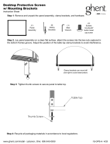
NOTE: For this procedure, refer to FIGURE 2.1.
WARNING
Pinch points may occur when returning the tilted seat to the full upright position.
Make sure the hands and body of both the occupant and attendants/bystanders are
clear of all pinch points before returning the tilted seat to the full upright position.
FIGURE 2.1 Pinch Points
Fully Tilted Seat
Pinch Point
Pinch Points

SECTION 3—EMI INFORMATION
2G Tarsys®Powered Seating System 18 Part No 1114842
SECTION 3—EMI INFORMATION
WARNING
CAUTION: IT IS VERY IMPORTANT THAT YOU READ THIS INFORMATION
REGARDING THE POSSIBLE EFFECTS OF ELECTROMAGNETIC
INTERFERENCE ON YOUR POWERED WHEELCHAIR.
Electromagnetic Interference (EMI) From Radio Wave Sources
Powered wheelchairs and motorized scooters (in this text, both will be referred to
as powered wheelchairs) may be susceptible to electromagnetic interference (EMI),
which is interfering electromagnetic energy (EM) emitted from sources such as
radio stations, TV stations, amateur radio (HAM) transmitters, two way radios, and
cellular phones. The interference (from radio wave sources) can cause the powered
wheelchair to release its brakes, move by itself, or move in unintended directions. It
can also permanently damage the powered wheelchair's control system. The
intensity of the interfering EM energy can be measured in volts per meter (V/m).
Each powered wheelchair can resist EMI up to a certain intensity. This is called its
“immunity level.” The higher the immunity level, the greater the protection. At
this time, current technology is capable of achieving at least a 20 V/m immunity
level, which would provide useful protection from the more common sources of
radiated EMI.
There are a number of sources of relatively intense electromagnetic fields in the
everyday environment. Some of these sources are obvious and easy to avoid.
Others are not apparent and exposure is unavoidable. However, we believe that by
following the warnings listed below, your risk to EMI will be minimized.
The sources of radiated EMI can be broadly classified into three types:
1) Hand-held Portable transceivers (transmitters-receivers with the antenna
mounted directly on the transmitting unit. Examples include: citizens band (CB)
radios, “walkie talkie”, security, fire and police transceivers, cellular telephones,
and other personal communication devices. NOTE: Some cellular telephones
and similar devices transmit signals while they are ON, even when not being
used;
2) Medium-range mobile transceivers, such as those used in police cars, fire trucks,
ambulances and taxis. These usually have the antenna mounted on the outside of
the vehicle; and
3) Long-range transmitters and transceivers, such as commercial broadcast
transmitters (radio and TV broadcast antenna towers) and amateur (HAM)
radios.
NOTE: Other types of hand-held devices, such as cordless phones, laptop computers,
AM/FM radios, TV sets, CD players, cassette players, and small appliances, such as
electric shavers and hair dryers, so far as we know, are not likely to cause EMI problems
to your powered wheelchair.

SECTION 3—EMI INFORMATION
Part No 1114842 19 2G Tarsys®Powered Seating System
WARNING
Powered Wheelchair Electromagnetic Interference (EMI)
Because EM energy rapidly becomes more intense as one moves closer to the
transmitting antenna (source), the EM fields from hand-held radio wave sources
(transceivers) are of special concern. It is possible to unintentionally bring high
levels of EM energy very close to the powered wheelchair's control system while
using these devices. This can affect powered wheelchair movement and braking.
Therefore, the warnings listed below are recommended to prevent possible
interference with the control system of the powered wheelchair.
Electromagnetic interference (EMI) from sources such as radio and TV stations,
amateur radio (HAM) transmitters, two-way radios, and cellular phones can affect
powered wheelchairs and motorized scooters.
FOLLOWING THE WARNINGS LISTED BELOW SHOULD REDUCE THE
CHANCE OF UNINTENDED BRAKE RELEASE OR POWERED WHEELCHAIR
MOVEMENT WHICH COULD RESULT IN SERIOUS INJURY.
1) DO NOT operate hand-held transceivers (transmitters receivers), such as
citizens band (CB) radios, or turn ON personal communication devices, such as
cellular phones, while the powered wheelchair is turned ON;
2) Be aware of nearby transmitters, such as radio or TV stations, and try to avoid
coming close to them;
3) If unintended movement or brake release occurs, turn the powered wheelchair
OFF as soon as it is safe;
4) Be aware that adding accessories or components, or modifying the powered
wheelchair, may make it more susceptible to EMI (NOTE: There is no easy way
to evaluate their effect on the overall immunity of the powered wheelchair); and
5) Report all incidents of unintended movement or brake release to the powered
wheelchair manufacturer, and note whether there is a source of EMI nearby.
Important Information
1) 20 volts per meter (V/m) is a generally achievable and useful immunity level
against EMI (as of May 1994) (the higher the level, the greater the protection);
2) This device has been tested to a radiated immunity level of 20 volts per meter.
3) The immunity level of the product is unknown.
Modification of any kind to the electronics of this wheelchair as manufactured by
Invacare may adversely affect the EMI immunity levels.

SECTION 4—SAFETY INSPECTION/TROUBLESHOOTING
2G Tarsys®Powered Seating System 20 Part No 1114842
SECTION 4—SAFETY
INSPECTION/TROUBLESHOOTING
Safety Inspection Checklist
These adjustments should be made whenever this product is serviced, especially as
part of the initial unit setup. Follow these procedures:
CAUTION
As with any vehicle, the wheels and tires should be checked periodically for cracks
and wear, and should be replaced.
❑ Make sure all electrical connections are secure.
❑ Check that cables are routed and secured properly to ensure that cables DO NOT
become entangled and damaged during normal operation of seating system.
❑ Make sure drive lock-out works properly.
❑ Make sure tilt operates smoothly and properly.
❑ Make sure recline operates smoothly and properly.
❑ Ensure all fasteners are secure on clothing guards.
❑ Ensure arms are secure but easy to release.
❑ Ensure arm adjustment levers operate and lock securely.
❑ Ensure adjustable height arms operate and lock securely.
❑ Inspect for rips in upholstery on armrests.
❑ Ensure armrest pad sits flush against arm tube.
❑ Inspect seat and back cushions for rips or sagging.
❑ Inspect hand grips for looseness. If loose, have them replaced by a qualified
technician.
❑ Inspect seat positioning strap for any signs of wear. Ensure buckle latches. Verify
hardware that attaches strap to frame is secure and undamaged. Replace if necessary.
❑ Check that all labels are present and legible. Replace if necessary.
/