Multitech MTPSR1-120 User manual
- Category
- Networking
- Type
- User manual
This manual is also suitable for

Dual Ethernet ProxyServer
Model MTPSR1-120
User Guide

User Guide
88301500 Revision A
Dual Ethernet ProxyServer (Model No MTPSR1-120)
This publication may not be reproduced, in whole or in part, without prior expressed written permission from
Multi-Tech Systems, Inc. All rights reserved.
Copyright © 1998, by Multi-Tech Systems, Inc.
Multi-Tech Systems, Inc. makes no representations or warranties with respect to the contents hereof and
specifically disclaims any implied warranties of merchantability or fitness for any particular purpose.
Furthermore, Multi-Tech Systems, Inc. reserves the right to revise this publication and to make changes from
time to time in the content hereof without obligation of Multi-Tech Systems, Inc. to notify any person or
organization of such revisions or changes.
Record of Revisions
Revision Description
A Manual released. All pages at revision A.
(9/4/98)
Patents
This Product is covered by one or more of the following U.S. Patent Numbers:
5.301.274; 5.309.562
;
5.355.365; 5.355.653; 5.452.289; 5.453.986
. Other Patents Pending.
TRADEMARK
Trademark of Multi-Tech Systems, Inc. is the Multi-Tech logo.
Windows is a registered trademark of Microsoft.
Multi-Tech Systems, Inc.
2205 Woodale Drive
Mounds View, Minnesota 55112
(612) 785-3500 or (800) 328-9717
Fax 612-785-9874
Tech Support (800) 972-2439
Internet Address: http://www.multitech.com
Fax-Back (612) 717-5888

Contents
Chapter 1 - Introduction and Description
Introduction ................................................................................................................................................ 6
Preview of this Guide ................................................................................................................................. 6
Front Panel Description.............................................................................................................................. 8
Back Panel Description .............................................................................................................................. 9
RS232/V.35 Connector ........................................................................................................................ 9
Ethernet 1 and 2 10Base-T Connectors .............................................................................................. 9
Command Connector........................................................................................................................... 9
Power Connector ................................................................................................................................. 9
Specifications ........................................................................................................................................... 10
Ethernet Ports.................................................................................................................................... 10
Command Port................................................................................................................................... 10
WAN Link ........................................................................................................................................... 10
Electrical/Physical.............................................................................................................................. 10
Chapter 2 - Installation
Safety Warnings ....................................................................................................................................... 12
Unpacking Your ProxyServer ................................................................................................................... 12
V.35 Shunt Procedure .............................................................................................................................. 13
Cabling Your ProxyServer ........................................................................................................................ 14
Chapter 3 - Software Loading and Configuration
Loading Your Software ............................................................................................................................. 18
IP Port Configuration.......................................................................................................................... 20
Default WAN Link Configuration ........................................................................................................ 21
Chapter 4 - Firewall Software
Introduction .............................................................................................................................................. 24
Typical Applications.................................................................................................................................. 24
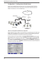
Configuration 1 - Cable/DSL Modem ................................................................................................. 24
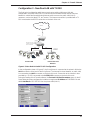
Configuration 2 - Existing Dual-LAN with Router ............................................................................... 26
Configuration 3 - New Dual-LAN with T1 DSU................................................................................... 27
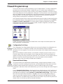
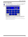
Firewall Program Group ........................................................................................................................... 29
Firewall Configuration............................................................................................................................... 31
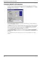
Changing IP Parameters .......................................................................................................................... 32
Changing WAN Port Parameters ............................................................................................................. 34
Adding Proxy Applications........................................................................................................................ 35
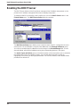
Enabling the DHCP Server....................................................................................................................... 36
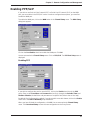
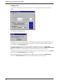
Enabling PPP/SLIP .................................................................................................................................. 37
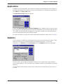
Applications.............................................................................................................................................. 39
Statistics................................................................................................................................................... 39
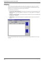
Filtering .................................................................................................................................................... 40
iii

Chapter 5 - Remote Configuration and Management
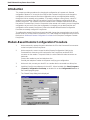
Introduction .............................................................................................................................................. 42
Modem-Based Remote Configuration Procedure..................................................................................... 42
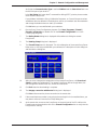
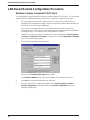
LAN-Based Remote Configuration Procedure ......................................................................................... 44
Windows Sockets Compliant TCP/IP Stack....................................................................................... 44
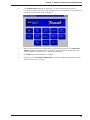
Remote Management ............................................................................................................................... 46
Telnet ................................................................................................................................................. 46
WEB Management............................................................................................................................. 48
Chapter 6 - Warranty, Service and Tech Support
Introduction .............................................................................................................................................. 50
Limited Warranty ...................................................................................................................................... 50
On-line Warranty Registration............................................................................................................ 50
Tech Support ............................................................................................................................................ 51
Recording ProxyServer Information................................................................................................... 51
Service ..................................................................................................................................................... 52
The Multi-Tech BBS ................................................................................................................................. 53
To Log on to the Multi-Tech BBS........................................................................................................ 53
To Download a File ............................................................................................................................ 53
About CompuServe.................................................................................................................................. 54
About the Internet..................................................................................................................................... 54
About the Multi-Tech Fax-Back Service ................................................................................................... 54
Appendixes
Appendix A - TCP/IP (Transmission Control Protocol/Internet Protocol) Description ............................... 56
Index
iv

Chapter 1 - Introduction and Description

6
Dual Ethernet ProxyServer User Guide
Introduction
Welcome to Multi-Tech's new Dual Ethernet ProxyServer, model number MTPSR1-120, a high
speed Internet access device that provides firewall protection to your corporate (secured) LAN
and allows Internet access to the Internet Services Network (public LAN) that resides outside the
firewall. Internet access can be provided through new technologies, such as cable or DSL
modems, connecting to an existing high speed public LAN, or connecting the RS232 WAN port
on the back of the unit that allows Internet access up to T1/E1 access speeds. The Dual Ethernet
ProxyServer provides two Ethernet connections that implement firewall protection and gateway
security for your LAN resources and provides megabit data transfer rates (up to 20 times faster
than a 56K modem) for your Internet access.
The Dual Ethernet ProxyServer provides two Ethernet 10Base-T ports which connect your
private secured LAN to the LAN 1 connection and the Internet Services Network resources to the
LAN 2 connection, and a Command port for configuration. An additional RS232/V.35 port is
provided for an alternate connection to an external WAN for connecting your secure corporate
LAN directly to an ISP. System management is provided through the command port using
bundled Windows® software which provides easy-to-use configuration menus.
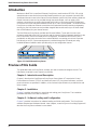
Figure 1-1. Dual Ethernet ProxyServer
Preview of this Guide
This guide describes the ProxyServer and tells you how to install and configure the unit. The
information contained in each chapter is as follows:
Chapter 1 - Introduction and Description
Chapter 1 describes the Dual Ethernet ProxyServer. Descriptions of Transmission Control
Protocol/Internet Protocol (TCP/IP) and Internet Protocol (IP), front panel indicators, and back
panel connectors are provided. In addition, a list of relevant specifications is provided at the end
of the chapter.
Chapter 2 - Installation
Chapter 2 provides information on unpacking and cabling your ProxyServer. The installation
procedure describes each cable connection.
Chapter 3 - Software Loading and Configuration
Chapter 3 provides instructions for software loading and initial configuration. The ProxyServer
software diskettes are Windows® based. Later chapters, as well as your on-line help program will
describe the ProxyServer software in more detail.

7
Chapter 1 - Introduction and Description
Chapter 4 - ProxyServer Software
Chapter 4 describes the ProxyServer software package designed for the Windows ®
environment. This chapter describes the ProxyServer software from an applications standpoint,
and in so doing, not every screen is shown, nor is each field within a screen defined. For
explanations and parameters of each field within a dialog box please refer to the on-line help
system provided within the software.
Chapter 5 - Remote Configuration and Management
Chapter 5 provides procedures for changing the configuration of a remote ProxyServer. Remote
configuration allows you to change the configuration of a unit by simply connecting two modems
between the two ProxyServers and remotely controlling the unit. In addition, remote management
utilities such as Telnet and Web-based management of the ProxyServer
Chapter 6 - Warranty, Service and Tech Support
Chapter 6 provides instructions on getting service for your ProxyServer at the factory, a
statement of the limited warranty, information about our Internet presence, and space for
recording information about your ProxyServer prior to calling Multi-Tech’s Technical Support.
Appendixes
Appendix A - TCP/IP (Transmission Control Protocol/Internet Protocol) Description

8
Dual Ethernet ProxyServer User Guide
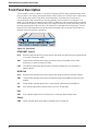
Front Panel Description
The front panel, shown in Figure 1-2, contains four groups of LEDs that provide the status of the
LAN connection, link activity, and general status of the ProxyServer. The Ethernet 1 and Ethernet
2 LEDs display the activity of the public and private LANs, in whether the ProxyServer is
connected to the LAN, transmitting or receiving packets, and if a collision is in progress. The
WAN Link LEDs display the status of the RS232/V.35 WAN link, that can optionally be connected
to an external DCE device, in whether the link is ready to transmit or receive serial data, and if an
external communications device with a V.35 interface is connected to the ProxyServer. The last
group of LEDs indicate whether the self test passed or failed and if the power On/Off switch on
the back of the ProxyServer is turned On.
Figure 1-2. Front Panel
ETHERNET 1 and 2
RCV Receive Data indicator blinks when packets are being received from the private (Ethernet
1) or public (Ethernet 2) LANs.
XMT Transmit Data indicator blinks when packets are being transmitted to the private
(Ethernet 1) or public (Ethernet 2) LANs.
LNK Link indicator lights when the Ethernet link senses voltage from a concentrator or
external device.
WAN Link
RCV Receive Data indicator blinks when packets are being sent to the local area network.
XMT Transmit Data indicator blinks when packets are being transmitted from the local area
network.
CD Carrier Detect indicator lights when a carrier signal is detected on the WAN link.
V35 V.35 indicator lights when internal shunt is set for V.35 operation.
Fail
ERR Error indicator lights when the ProxyServer is booting or downloading setup.
Power
PWR Power indicator lights when power is applied to the ProxyServer.

9
Chapter 1 - Introduction and Description
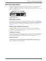
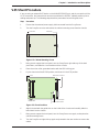
Back Panel Description
The cable connections for the ProxyServer are made at the back panel. In addition to the Power
connector, Three groups of connectors are used on the ProxyServer: the Command Port,
Ethernet 1 & 2 (10BASET) and RS232/V.35. The cable connections are shown in Figure 1-3 and
defined in the following groups.
2
ETHERNET
COMMAND
10BASET
10BASET
ON
OFF
1
RS232/V.35
POWER
Figure 1-3. Back Panel
RS232/V.35 Connector
The RS232/V.35 (DB-25) connector is used to connect the ProxyServer to an external modem,
DSU, or other Data Communications Equipment (DCE). This connection can be either RS232C
(default) or V.35. If the connection is V.35, then the shunt must be moved from the default RS232
position to the V.35 position (for details on this procedure, refer to Chapter 2 - V.35 Shunt
Procedure).
Ethernet 1 and 2 10Base-T Connectors
The Ethernet 10Base-T connectors are used to connect the ProxyServer to a LAN using
unshielded twisted cable. Ethernet 1 connects the private LAN, and Ethernet 2 connects the
public LAN. These connectors are RJ-45 jacks.
Command Connector
The Command connector is used to configure the ProxyServer using a PC with a serial port and
running Windows® software. The Command connector is an RJ-45 jack and a short adapter
cable is provided to convert to a standard serial port DB-25 female connector.
Power Connector
The Power connector is used to connect the external power supply to the ProxyServer. The
Power connector is a 6-pin circular DIN connector. A separate power cord is connected to the
power supply and the live AC grounded outlet.

10
Dual Ethernet ProxyServer User Guide
Specifications
• Protocols - Point-To-Point Protocol (PPP), and Serial Line Internet Protocol (SLIP)
Ethernet Ports
• Two Ethernet Interface - 10Base-T (twisted pair) RJ-45 connectors.
Command Port
• Single 19.2K bps asynchronous Command Port using a short RJ-45 to DB-25 cable with a
DB-25 female connector
WAN Link
• One RS232/V.35 port connector.
Electrical/Physical
• Voltage - 115 VAC (Standard), 240 Volts AC (Optional)
• Frequency - 47 to 63 Hz
• Power Consumption - 10 Watts
• Dimensions - 1.625" high x 6" wide x 9" deep
5.63cm high x 22.34cm wide x 33.51cm deep
• Weight - 2 pounds (.92 kg)

Chapter 2 - Installation

12
Dual Ethernet ProxyServer User Guide
Safety Warnings
1. Never install telephone wiring during a lightning storm.
2. Never install telephone jacks in wet locations unless the jack is specifically designed for
wet locations.
3. Never touch uninsulated telephone wires or terminals unless the telephone line has been
disconnected at the network interface.
4. Use caution when installing or modifying telephone lines.
5. Avoid using a telephone (other than a cordless type) during an electrical storm. There
may be a remote risk of electrical shock from lightning.
6. Do not use the telephone to report a gas leak in the vicinity of the leak.
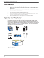
Unpacking Your ProxyServer
The shipping box contains the Dual Ethernet ProxyServer, external power supply, power cord,
Command Port (DB-25 to RJ-45) cable, your Quick Start Guide, and three diskettes (i.e., the
ProxyServer User Guide, and the ProxyServer Software). Inspect the contents for signs of any
shipping damage. If damage is observed, do not power up the unit, contact Multi-Tech’s Technical
Support for advice (refer to Chapter 6). If no damage is observed, place the ProxyServer in its
final location and continue with the next section.
MADE IN U.S.A
MADE IN U.S.A
Figure 2-1. Unpacking

13
Chapter 1 - Introduction and Description
V.35 Shunt Procedure
If you are using an external DCE device on the WAN RS232/V.35 port, and the connection will be
a V.35 connection, the internal shunt must be moved from the RS232C (default) position prior to
cabling and power-up. The following steps detail the procedures for switching the shunt.
Step Procedure
1 Ensure that the external power supply is disconnected from the ProxyServer.
2 Turn the ProxyServer over and remove the cabinet mounting screw from the chassis.
Front Panel
Back Panel
Cabinet Mounting Screw
Figure 2-2. Cabinet Mounting Screw
3 Being sure to support the back panel, turn the ProxyServer right-side-up, tilt the back
panel down, and slide the circuit board out of the chassis.
4 Place the unit on a flat, grounded surface with the LED’s facing you.
5 Pry the shunt out of the RS232 position, and insert it in the V.35 position.
V.35 Shunt Position
RS232C Shunt Position
Back Panel Connectors
RAM Sockets
LEDs
Figure 2-3. Shunt Positions
6 Align the board with the guide slots on the inside of the chassis and carefully slide the
board back into the chassis.
7 Being sure to support the back panel, turn the ProxyServer over again, and replace the
cabinet mounting screw.
8 Turn the ProxyServer right-side-up again and proceed to the next section to connect the
cables.

14
Dual Ethernet ProxyServer User Guide
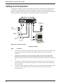
Cabling Your ProxyServer
Cabling your ProxyServer involves making the proper Power, Command Port, and two Ethernet
connections. An optional WAN connection is provided to connect to an external WAN device.
Figure 2-4 shows the back panel connectors and the associated cable connections, and the table
that follows details the procedures for connecting the cables to your ProxyServer.
Power
Connection
PC
Connection
Secured
LAN
Internet
LAN
WAN
Connection
2
ETHERNET
COMMAND
10BASET
10BASET
ON
OFF
1
RS232/V.35
POWER
Figure 2-4. Cable Connections
Cabling Procedure
Step Procedure
1. Connect one end of the power supply to a live AC outlet and connect the other end to the
ProxyServer as shown in Figure 2-4. The power connector is a 6-pin circular DIN
connector.
2. Connect the ProxyServer to a PC by using the short RJ-45 to DB-25 (female) cable
provided in your unit. Plug the RJ-45 end of the cable into the Command port of the
ProxyServer and the other end into the RS-232 cable from the PC serial port. See Figure
2-4.
3. To connect your secure (private) LAN, connect one end of an RJ-45 (UTP) cable to the
LAN 1 connector on the back of the ProxyServer. Connect the other end of the cable to
your private LAN.
4. To connect a cable modem, DSL modem, or your Internet (public) LAN, connect one end
of an RJ-45 (UTP) cable to the LAN 2 connector on the back of the ProxyServer.
Proceed to step 6.

15
Chapter 2 - Installation
Table 2-1. (cont’d.)
Step Procedure
5. If a cable modem, DSL modem, or your Internet LAN is being used, no cable connection
will be made to the RS232/V.35 connector on the back of the ProxyServer.
If the RS232/V.35 connector on the ProxyServer is going to be connected to a WAN
device (i.e., connecting your secure (private) LAN to an ISP, connect one end of an
RS232 or V.35 interface cable to the RS232/V.35 connector on the back of the
ProxyServer. Connect the other end of this cable to the WAN device.
6. Turn on power to the ProxyServer by placing the ON/OFF switch on the back panel to
the ON position. Wait for the Fail LED on the ProxyServer to go OFF before proceeding.
This may take a couple of minutes to go OFF.
At this time your ProxyServer is completely cabled. Proceed to Chapter 3 to load the Firewall
software.

16
Dual Ethernet ProxyServer User Guide

Chapter 3 - Software Loading and Configuration

18
Dual Ethernet ProxyServer User Guide
Loading Your Software
The following loading procedure does not provide every screen or option in the process of
installing the Firewall software. The assumption is that the installation is being performed by a
technical person with a thorough knowledge of Windows and the software loading process.
Additional information on the Firewall software is provided in the Chapter 4, and in the on-line
help provided with your Firewall software.
1. Run Windows on the PC connected to the Command Port.
2. Insert the ProxyServer diskette labeled
Disk 1
into the disk drive on the PC connected to
the Command port.
3. Win3.1 users - In Program Manager click File | Run. In the Run dialog box, type
a:\setup or b:\setup (depending on the location of your floppy disk drive) in the
Command Line field and then click OK.
Win95 users - click Start | Run. In the Run dialog box click on the down arrow and
choose a:\setup or b:\setup (depending on the location of your floppy disk drive) in the
Command Line field and then click OK.
4. Follow the on-screen instructions to install your Firewall software.

19
Chapter 3 - Software Loading and Configuration
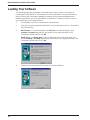
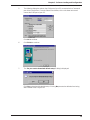
5. The following dialog box selects the COM port of your PC connected to the Command
port of the ProxyServer. From the Select Port window, click on the down arrow and
choose the COM port of your PC.
Click OK to continue.
6. Click Finish to continue.
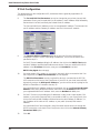
7. The “Do you want to download default setup?” dialog is displayed.
Click Yes to download the default setup. Clicking No prevents the defaults from being
down loaded to the ProxyServer.

20
Dual Ethernet ProxyServer User Guide
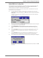
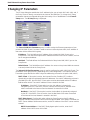
IP Port Configuration
This dialog allows for the configuration of IP parameters that are generally applicable to IP
proxying on all ports.
8. The Secured LAN Port Parameters have to be changed to your private (secure) LAN
parameters. Enter your Secured LAN Port IP Address in the IP Address field, followed by
the Net Mask in its field, and finally the Default Route IP address.
The Secured LAN Port IP Address can be an unregistered IP address. The Internet LAN
port IP address and the Gateway IP address must be in the same IP network.
9. The Internet LAN Port Parameters depend on how LAN 2 on the ProxyServer is
configured. If a DHCP Server is providing IP addresses, click on the OK button and
proceed to step 13.
If a DHCP Server is not providing the IP address, then click on the DHCP Client option
and the IP Address and Net Mask fields become active. Enter your valid Public LAN IP
address in the IP Address field, also, enter your valid Net Mask in its field.
DHCP Relay Agent does not apply.
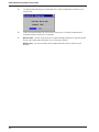
10. If a cable modem, DSL modem, or your public (Internet) LAN is connected to LAN 2 on
the ProxyServer, the WAN Port Parameters are not required.
The WAN Port Parameters are only required if a device is connected to the RS-232/
V.35 connector on the back of the ProxyServer. If your ISP for your local (secured LAN)
dynamically assigns the WAN port IP addresses, you do not have to do anything for the
WAN Port Parameters. Proceed to the step 12.
If a static WAN Port IP address needs to be assigned, click on the ISP assigns Dynamic
Address check box to disable the feature, then click on the IP Address field and enter
your registered WAN Port IP address. Also, enter the Net Mask for WAN port.
11. If a DHCP Server is not providing the IP addresses in step 9 and a cable modem, DSL
modem, or your public (Internet) LAN is connected to LAN 2 on your ProxyServer, then
click on the Internet LAN IP Address field and enter the valid Gateway IP address (i.e.,
the IP address of the cable or DSL modem, or your public (Internet) LAN router’s
address).
If a static WAN Port IP was assigned in step 10 and the Internet access is through the
RS232 connection on the back of the ProxyServer, then click on the Internet Gateway
Parameters WAN option.
12. Click OK.
Page is loading ...
Page is loading ...
Page is loading ...
Page is loading ...
Page is loading ...
Page is loading ...
Page is loading ...
Page is loading ...
Page is loading ...
Page is loading ...
Page is loading ...
Page is loading ...
Page is loading ...
Page is loading ...
Page is loading ...
Page is loading ...
Page is loading ...
Page is loading ...
Page is loading ...
Page is loading ...
Page is loading ...
Page is loading ...
Page is loading ...
Page is loading ...
Page is loading ...
Page is loading ...
Page is loading ...
Page is loading ...
Page is loading ...
Page is loading ...
Page is loading ...
Page is loading ...
Page is loading ...
Page is loading ...
Page is loading ...
Page is loading ...
Page is loading ...
Page is loading ...
Page is loading ...
Page is loading ...
-
 1
1
-
 2
2
-
 3
3
-
 4
4
-
 5
5
-
 6
6
-
 7
7
-
 8
8
-
 9
9
-
 10
10
-
 11
11
-
 12
12
-
 13
13
-
 14
14
-
 15
15
-
 16
16
-
 17
17
-
 18
18
-
 19
19
-
 20
20
-
 21
21
-
 22
22
-
 23
23
-
 24
24
-
 25
25
-
 26
26
-
 27
27
-
 28
28
-
 29
29
-
 30
30
-
 31
31
-
 32
32
-
 33
33
-
 34
34
-
 35
35
-
 36
36
-
 37
37
-
 38
38
-
 39
39
-
 40
40
-
 41
41
-
 42
42
-
 43
43
-
 44
44
-
 45
45
-
 46
46
-
 47
47
-
 48
48
-
 49
49
-
 50
50
-
 51
51
-
 52
52
-
 53
53
-
 54
54
-
 55
55
-
 56
56
-
 57
57
-
 58
58
-
 59
59
-
 60
60


Multitech MTPSR1-120 User manual
- Category
- Networking
- Type
- User manual
- This manual is also suitable for
Ask a question and I''ll find the answer in the document
Finding information in a document is now easier with AI
Related papers
-
Multitech MTPSR1-202ST User manual
-
-
Multitech ISI551PC User manual
-
-
-
-
-
-
-
Other documents
-
Zoom 10BaseT User manual
-
Netcomm NF15ACV Owner's manual
-
Polycom HDA50 Administrator's Manual
-
-
Poly OBi508 Deployment Guide
-
-
Poly HDA50 Deployment Guide
-
-
Asus RT-N56U WEU7823 Owner's manual
-
Asus RT-AC66U WEU7417 User manual