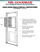
Overlay Door Panel—Model 424
I
nspect the door panel for the minimum
5
/8"
(16) thickness,
the finished inside edge. The glass door has a 10 lbs (5 kg)
weight limit. Refer to the wine storage section of the
Sub-Zero design guide for additional panel information.
Decide if the handle will be attached through the glass
door frame or just through the decorative door panel. If it
is just through the door panel, the handle must be
attached first.
Decorative panels are attached to the model 424 door
using #8 x
5
/8" square drive screws passing through the
door frame from the rear, behind the gasket into the panel.
The door panel is marked for screw locations by the use of
‘tenon centers’, which are temporarily inserted into the
1
/4" (6) diameter holes in the front of the glass door frame.
Refer to the illustration below.
With the wine storage unit secured in position and the
door closed, the panel is held in the desired position on
the door and rapped by hand from the front, putting center
marks on the rear surface of the panel. If the door panel is
made of such a material that pre-drilling is needed, all of
the mounting holes should be marked. If not, only enough
holes to hold the panel in place temporarily, are necessary.
T
he door panel is then lowered from the door frame, tenon
centers removed, the door opened and the screws driven
into the panel through the black tape on the door frame,
using the center marks to locate the screws.
The screw holes inside the door are hidden under a cover
flap on the door gasket. It is necessary to lift the flap to
insert the screws. Use as many screws as necessary to
hold the door panel in place properly.
IMPORTANT NOTE: After the first three or four mounting
screws are in place, but not completely tightened, close
the door and check your panel fit. This is the time to make
small adjustments. Once you are satisfied with the appear-
ance, open the door and apply the remainder of the
screws. Check all screws for tightness.
The metal frame on the glass door has numerous
mounting holes on each side of the door. This is to
accommodate the Sub-Zero accessory handles and
provide for easy attachment of the handle through the
door frame.
If you choose not to use the pre-drilled handle mounting
holes, it will be necessary to fasten the handle from the
rear of the door panel only, or drill one or more additional
holes through the metal frame of the glass door.
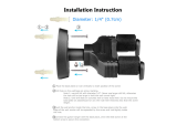
The cross section illustration shows how this hole passes
through the door frame. The hole center is on the small
locator groove in the front of the frame. A
1
/4" (6) diameter
hole is made in the front wall of the extrusion and a
13
/32"
(11) diameter hole through the rest of the frame.
Models 424 and 424FS Installation 13
subzero.com
Overlay panel. Door frame cross section.
GASKET
GLASS
13
/32" (11)
DIAMETER
1
/4" (6)
DIAMETER
OVERLAY
PANEL
DOOR
FRAME
TENON CENTER