Mitsubishi Electric A171SHCPUN User manual
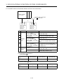
- Category
- Noise Reduction Machine
- Type
- User manual
This manual is also suitable for

MOTION CONTROLLER
User’s Manual
type A173UHCPU,A172SHCPUN,
A171SHCPUN
MITSUBISHI
ELECTRIC
MOTION CONTROLLER User’s Manual, type A173UHCPU,A172SHCPUN,A171SHCPUN

− I −
INTORODUCTION
Thank you for purchasing the Mitsubishi Motion Controller/A173UHCPU/A172SHCPUN/A171SHCPUN.
This instruction manual describes the handing and precautions of this unit. Incorrect handing will lead to
unforeseen events, so we ask that you please read this manual thoroughly and use the unit correctly.
Please make sure that this manual is delivered to the final user of the unit and that it is stored for future
reference.
Precautions for Safety
Please read this instruction manual and enclosed documents before starting installation, opera-
tion, maintenance or inspections to ensure correct usage. Thoroughly understand the machine,
safety information and precautions before starting operation.
The safety precautions are ranked as "Warning" and "Caution" in this instruction manual.
WARNING
When a dangerous situation may occur if handling is mistaken
leading to fatal or major injuries.
CAUTION
When a dangerous situation may occur if handling is mistaken
leading to medium or minor injuries, or physical damage.
Note that some items described as cautions may lead to major results depending on the
situation. In any case, important information that must be observed is described.

− II −
For Sate Operations
1. Prevention of electric shocks
WARNING
Never open the front case or terminal covers while the power is ON or the unit is running, as
this may lead to electric shocks.
Never run the unit with the front case or terminal cover removed. The high voltage terminal
and charged sections will be exposed and may lead to electric shocks.
Never open the front case or terminal cover at times other than wiring work or periodic
inspections even if the power is OFF. The insides of the control unit and servo amplifier are
charged and may lead to electric shocks.
When performing wiring work or inspections, turn the power OFF, wait at least ten minutes,
and then check the voltage with a tester, etc. Failing to do so may lead to electric shocks.
Always ground the control unit, servo amplifier and servomotor with Class 3 grounding. Do
not ground commonly with other devices.
The wiring work and inspections must be done by a qualified technician.
Wire the units after installing the control unit, servo amplifier and servomotor. Failing to do
so may lead to electric shocks or damage.
Never operate the switches with wet hands, as this may lead to electric shocks.
Do not damage, apply excessive stress, place heavy things on or sandwich the cables, as
this may lead to electric shocks.
Do not touch the control unit, servo amplifier or servomotor terminal blocks while the power
is ON, as this may lead to electric shocks.
Do not touch the internal power supply, internal grounding or signal wires of the control unit
and servo amplifier, as this may lead to electric shocks.
2. For fire prevention
CAUTION
Install the control unit, servo amplifier, servomotor and regenerative resistor on inflammable
material. Direct installation on flammable material or near flammable material may lead to
fires.
If a fault occurs in the control unit or servo amplifier, shut the power OFF at the servo
amplifier’s power source. If a large current continues to flow, fires may occur.
When using a regenerative resistor, shut the power OFF with an error signal. The regenera-
tive resistor may abnormally overheat due to a fault in the regenerative transistor, etc., and
may lead to fires.
Always take heat measures such as flame proofing for the inside of the control panel where
the servo amplifier or regenerative resistor is installed and for the wires used. Failing to do
so may lead to fires.

− III −
3. For injury prevention
CAUTION
Do not apply a voltage other than that specified in the instruction manual on any terminal.
Doing so may lead to destruction or damage.
Do not mistake the terminal connections, as this may lead to destruction or damage.
Do not mistake the polarity (+/-), as this may lead to destruction or damage.
The servo amplifier's heat radiating fins, regenerative resistor and servo amplifier, etc., will
be hot while the power is ON and for a short time after the power is turned OFF. Do not
touch these parts as doing so may lead to burns.
Always turn the power OFF before touching the servomotor shaft or coupled machines, as
these parts may lead to injuries.
Do not go near the machine during test operations or during operations such as teaching.
Doing so may lead to injuries.
4. Various precautions
Strictly observe the following precautions.
Mistaken handling of the unit may lead to faults, injuries or electric shocks.
(1) System structure
CAUTION
Always install a leakage breaker on the control unit and servo amplifier power source.
If installation of a magnetic contactor for power shut off during an error, etc., is specified in
the instruction manual for the servo amplifier, etc., always install the magnetic contactor.
Install an external emergency stop circuit so that the operation can be stopped immediately
and the power shut off.
Use the control unit, servo amplifier, servomotor and regenerative resistor with the combi-
nations listed in the instruction manual. Other combinations may lead to fires or faults.
If safety standards (ex., robot safety rules, etc.,) apply to the system using the control unit,
servo amplifier and servomotor, make sure that the safety standards are satisfied.
If the operation during a control unit or servo amplifier error and the safety direction
operation of the control unit differ, construct a countermeasure circuit externally of the
control unit and servo amplifier.
In systems where coasting of the servomotor will be a problem during emergency stop,
servo OFF or when the power is shut OFF, use dynamic brakes.
Make sure that the system considers the coasting amount even when using dynamic
brakes.
In systems where perpendicular shaft dropping may be a problem during emergency stop,
servo OFF or when the power is shut OFF, use both dynamic brakes and magnetic brakes.
The dynamic brakes must be used only during emergency stop and errors where servo OFF
occurs. These brakes must not be used for normal braking.
The brakes (magnetic brakes) assembled into the servomotor are for holding applications,
and must not be used for normal braking.
Construct the system so that there is a mechanical allowance allowing stopping even if the
stroke end limit switch is passed through at the max. speed.
Use wires and cables that have a wire diameter, heat resistance and bending resistance
compatible with the system.

− IV −
CAUTION
Use wires and cables within the length of the range described in the instruction manual.
The ratings and characteristics of the system parts (other than control unit, servo amplifier,
servomotor) must be compatible with the control unit, servo amplifier and servomotor.
Install a cover on the shaft so that the rotary parts of the servomotor are not touched during
operation.
There may be some cases where holding by the magnetic brakes is not possible due to the
life or mechanical structure (when the ball screw and servomotor are connected with a
timing belt, etc.). Install a stopping device to ensure safety on the machine side.
(2) Parameter settings and programming
CAUTION
Set the parameter values to those that are compatible with the control unit, servo amplifier,
servomotor and regenerative resistor model and the system application. The protective
functions may not function if the settings are incorrect.
The regenerative resistor model and capacity parameters must be set to values that
conform to the operation mode, servo amplifier and servo power unit. The protective
functions may not function if the settings are incorrect.
Set the mechanical brake output and dynamic brake output validity parameters to values
that are compatible with the system application. The protective functions may not function if
the settings are incorrect.
Set the stroke limit input validity parameter to a value that is compatible with the system
application. The protective functions may not function if the setting is incorrect.
Set the servomotor encoder type (increment, absolute position type, etc.) parameter to a
value that is compatible with the system application. The protective functions may not
function if the setting is incorrect.
Set the servomotor capacity and type (standard, low-inertia, flat, etc.) parameter to values
that are compatible with the system application. The protective functions may not function if
the settings are incorrect.
Set the servo amplifier capacity and type parameters to values that are compatible with the
system application. The protective functions may not function if the settings are incorrect.
Use the program commands for the program with the conditions specified in the instruction
manual.
Set the sequence function program capacity setting, device capacity, latch validity range, I/O
assignment setting, and validity of continuous operation during error detection to values that
are compatible with the system application. The protective functions may not function if the
settings are incorrect.
Some devices used in the program have fixed applications, so use these with the conditions
specified in the instruction manual.
The input devices and data registers assigned to the link will hold the data previous to when
communication is terminated by an error, etc. Thus, an error correspondence interlock
program specified in the instruction manual must be used.
Use
the interlock program specified in the special function unit's instruction manual for the
program corresponding to the special function unit.

− V −
(3) Transportation and installation
CAUTION
Transport the product with the correct method according to the weight.
Use the servomotor suspension bolts only for the transportation of the servomotor. Do not
transport the servomotor with machine installed on it.
Do not stack products past the limit.
When transporting the control unit or servo amplifier, never hold the connected wires or
cables.
When transporting the servomotor, never hold the cables, shaft or detector.
When transporting the control unit or servo amplifier, never hold the front case as it may fall
off.
When transporting, installing or removing the control unit or servo amplifier, never hold the
edges.
Install the unit according to the instruction manual in a place where the weight can be withstood.
Do not get on or place heavy objects on the product.
Always observe the installation direction.
Keep the designated clearance between the control unit or servo amplifier and control panel
inner surface or the control unit and servo amplifier, control unit or servo amplifier and other
devices.
Do not install or operate control units, servo amplifiers or servomotors that are damaged or
that have missing parts.
Do not block the intake/outtake ports of the servomotor with cooling fan.
Do not allow conductive matter such as screw or cutting chips or combustible matter such
as oil enter the control unit, servo amplifier or servomotor.
The control unit, servo amplifier and servomotor are precision machines, so do not drop or
apply strong impacts on them.
Securely fix the control unit and servo amplifier to the machine according to the instruction
manual. If the fixing is insufficient, these may come off during operation.
Always install the servomotor with reduction gears in the designated direction. Failing to do
so may lead to oil leaks.
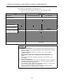
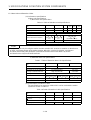
Store and use the unit in the following environmental conditions.
Conditions
Environment
Control unit/servo amplifier Servomotor
Ambient
temperature
0
°
C to
+
55
°
C
(With no freezing)
0
°
C to
+
40
°
C
(With no freezing)
Ambient humidity
According to each instruction
manual.
80
%
RH or less
(With no dew condensation)
Storage
temperature
According to each instruction
manual.
−
20
°
C to
+
65
°
C
Atmosphere
Indoors (where not subject to direct sunlight).
No corrosive gases, flammable gases, oil mist or dust must exist
Altitude 1000m (3278.69ft.) or less above sea level
Vibration According to each instruction manual

− VI −
CAUTION
When coupling with the synchronization encoder or servomotor shaft end, do not apply
impact such as by hitting with a hammer. Doing so may lead to detector damage.
Do not apply a load larger than the tolerable load onto the servomotor shaft. Doing so may
lead to shaft breakage.
When not using the unit for a long time, disconnect the power line from the control unit or
servo amplifier.
Place the control unit and servo amplifier in static electricity preventing vinyl bags and store.
When storing for a long time, please consult our sales representative.
(4) Wiring
CAUTION
Correctly and securely wire the wires. Reconfirm the connections for mistakes and the
terminal screws for tightness after wiring. Failing to do so may lead to run away of the
servomotor.
After wiring, install the protective covers such as the terminal covers to the original positions.
Do not install a phase advancing capacitor, surge absorber or radio noise filter (option FR-
BIF) on the output side of the servo amplifier.
Correctly connect the output side (terminals U, V, W). Incorrect connections will lead the
servomotor to operate abnormally.
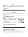
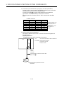
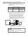
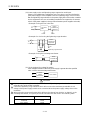
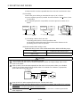
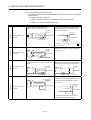
Do not connect a commercial
power supply to the servomotor, as this may lead to trouble.
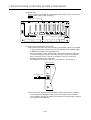
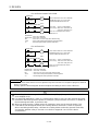
Do not mistake the direction of the surge absorbing diode
installed on the DC relay for the control signal output of
brake signals, etc. Incorrect installation may lead to signals
not being output when trouble occurs or the protective
functions not functioning.
Do not connect or disconnect the connection cables
between each unit, the encoder cable or sequence ex-
pansion cable while the power is ON.
Servo amplifier
VIN
(24VDC)
Control output
signal
RA
Securely tighten the cable connector fixing screws and fixing mechanisms. Insufficient fixing
may lead to the cables combing off during operation.
Do not bundle the power line or cables.
(5) Trial operation and adjustment
CAUTION
Confirm and adjust the program and each parameter before operation. Unpredictable
movements may occur depending on the machine.
Extreme adjustments and changes may lead to unstable operation, so never make them.
When using the absolute position system function, on starting up, and when the controller or
absolute value motor has been replaced, always perform a home position return.

− VII −
(6) Usage methods
CAUTION
Immediately turn OFF the power if smoke, abnormal sounds or odors are emitted from the
control unit, servo amplifier or servomotor.
Always execute a test operation before starting actual operations after the program or
parameters have been changed or after maintenance and inspection.
The units must be disassembled and repaired by a qualified technician.
Do not make any modifications to the unit.
Keep the effect or magnetic obstacles to a minimum by installing a noise filter or by using
wire shields, etc. Magnetic obstacles may affect the electronic devices used near the control
unit or servo amplifier.
When using the CE Mark-compliant equipment, refer to the "EMC Installation Guidelines"
(data number IB(NA)-67339) for the motion controllers and refer to the corresponding EMC
guideline information for the servo amplifiers, inverters and other equipment.
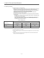
Use the units with the following conditions.
Conditions
Item
A1S61PN A1S62PN
CPU module's built-
in power supply
Input power
100 to 240VAC
+10%
(85 to 264VAC)
-15%
Input frequency 50/60Hz 5%
Tolerable momentary
power failure
Within 20ms
(7) Remedies for errors
CAUTION
If an error occurs in the self diagnosis of the control unit or servo amplifier, confirm the
check details according to the instruction manual, and restore the operation.
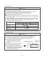
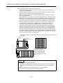
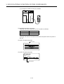
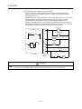
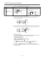
If a dangerous state is predicted in case of a power failure or product failure, use a
servomotor with magnetic brakes or install a brake mechanism externally.
Use a double circuit construction so that the
magnetic brake operation circuit can be
operated by emergency stop signals set
externally.
If an error occurs, remove the cause, secure
the safety and then resume operation.
The unit may suddenly resume operation
after a power failure is restored, so do not go
near the machine. (Design the machine so
that personal safety can be ensured even if
the machine restarts suddenly.)
Shut off with servo ON signal OFF,
alarm, magnetic brake signal.
Servo motor
Magnetic
brakes
RA1
EMG
24VDC
Shut off with the
emergency stop
signal(EMG).

− VIII −
(8) Maintenance, inspection and part replacement
CAUTION
Perform the daily and periodic inspections according to the instruction manual.
Perform maintenance and inspection after backing up the program and parameters for the
control unit and servo amplifier.
Do not place fingers or hands in the clearance when opening or closing any opening.
Periodically replace consumable parts such as batteries according to the instruction manual.
Do not touch the lead sections such as ICs or the connector contacts.
Do not place the control unit or servo amplifier on metal that may cause a power leakage or
wood, plastic or vinyl that may cause static electricity buildup.
Do not perform a megger test (insulation resistance measurement) during inspection.
When replacing the control unit or servo amplifier, always set the new unit settings correctly.
When the controller or absolute value motor has been replaced, carry out a home position
return operation using one of the following methods, otherwise position displacement could
occur.
1) After writing the servo data to the PC using peripheral device software, switch on the
power again, then perform a home position return operation.
2) Using the backup function of the peripheral device software, load the data backed up
before replacement.
After maintenance and inspections are completed, confirm that the position detection of the
absolute position detector function is correct.
Do not short circuit, charge, overheat, incinerate or disassemble the batteries.
The electrolytic capacitor will generate gas during a fault, so do not place your face near the
control unit or servo amplifier.
The electrolytic capacitor and fan will deteriorate. Periodically change these to prevent
secondary damage from faults. Replacements can be made by our sales representative.
(9) Disposal
CAUTION
Dispose of this unit as general industrial waste.
Do not disassemble the control unit, servo amplifier or servomotor parts.
Dispose of the battery according to local laws and regulations.
(10) General cautions
CAUTION
All drawings provided in the instruction manual show the state with the covers and safety
partitions removed to explain detailed sections. When operating the product, always return
the covers and partitions to the designated positions, and operate according to the
instruction manual.

Revisions
*The manual number is given on the bottom left of the back cover.
Print Date *Manual Number Revision
Apr.1998 IB(NA)-67395-B First edition
Sep.2000 IB(NA)-67395-C
Addition
Addition of information on the A173UHCPU
Correction
For Sate Operations (4. Various precautions (3), (6), (8)), CONTENTS, 1.1,
1.2.1, 1.2.2, 1.3, 1.4, 1.5.1, 1.5.2 (1), 1.5.3, 1.5.4, 1.5.5, 1.5.6, 2.1, 2.3, 2.3.1,
2.3.2 (2), 4.3, 4.4, 5.4.1, 5.4.1(3), 5.4.1 (4), 5.4.1 (5), APPENDICES
Delete
1.5.7 (2), 5.3.1 (2)
This manual confers no industrial property rights or any rights of any other kind, nor does it confer any patent
licenses. Mitsubishi Electric Corporation cannot be held responsible for any problems involving industrial
property rights which may occur as a result of using the contents noted in this manual.
© 2000 Mitsubishi Electric Corporation

− I −
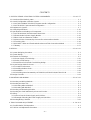
CONTENTS
1. SPECIFICATIONS OF MOTION SYSTEM COMPONENTS.....................................................1- 1 to 1-57
1.1 Overview of the Motion System......................................................................................................... 1- 1
1.2 Overall Configuration of Motion System ............................................................................................ 1- 3
1.2.1 A172SHCPUN/A171SHCPUN System Overall Configuration.................................................... 1- 3
1.2.2 A173UHCPU System Overall Configuration............................................................................... 1- 5
1.3 Equipment in System......................................................................................................................... 1- 7
1.4 General Specifications...................................................................................................................... 1-10
1.5 Specifications and Settings of Components ..................................................................................... 1-11
1.5.1 A173UHCPU/A172SHCPUN/A171SHCPUN............................................................................. 1-11
1.5.2 Extension Base Power Supply Module...................................................................................... 1-25
1.5.3 Base Units and Extension Cables.............................................................................................. 1-28
1.5.4 Manual Pulse Generator/Synchronous Encoder Interface Module............................................ 1-38
1.5.5 Teaching Unit ............................................................................................................................. 1-49
1.5.6 SSCNET Cables and Termination Resistor and Their Connection Method .............................. 1-53
1.5.7 Battery........................................................................................................................................ 1-57
2. DESIGN......................................................................................................................................2- 1 to 2-22
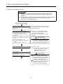
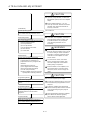
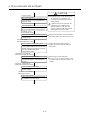
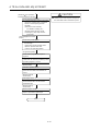
2.1 System Designing Procedure ............................................................................................................ 2- 1
2.2 System Design................................................................................................................................... 2- 4
2.3 External Circuit Design....................................................................................................................... 2- 5
2.3.1 Power Supply Circuit Design...................................................................................................... 2-10
2.3.2 Safety Circuit Design.................................................................................................................. 2-12
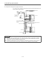
2.3.3 Instructions for External Circuit Wiring Design...........................................................................2-16
2.4 Layout Design within Enclosure........................................................................................................ 2-17
2.4.1 Location Environment................................................................................................................. 2-17
2.4.2 Installing the Base Units............................................................................................................. 2-18
2.4.3 Installation .................................................................................................................................. 2-19
2.4.4 Calculating Heat Generated by A173UHCPU/A172SHCPUN/A171SHCPUN.......................... 2-20
2.5 Design Checklist ............................................................................................................................... 2-22
3. MOUNTING AND WIRING.........................................................................................................3- 1 to 3-12
3.1 Mounting and Wiring Methods ........................................................................................................... 3- 1
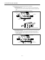
3.2 Mounting the Base Unit...................................................................................................................... 3- 1
3.2.1 Mounting without DIN Rail........................................................................................................... 3- 2
3.2.2 Mounting with DIN Rail................................................................................................................ 3- 2
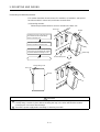
3.3 Mounting and Removing Modules ..................................................................................................... 3- 4
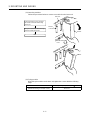
3.4 Mounting the Serial Absolute Synchronous Encoder ........................................................................ 3- 7
3.5 Wiring................................................................................................................................................. 3- 9
3.5.1 How to Run the Power Supply and I/O Wires............................................................................. 3- 9
3.5.2 Example of Routing the Power Supply and I/O Wires ............................................................... 3-11
3.6 Mounting/Wiring Checklist ................................................................................................................ 3-12
4. TRIAL RUN AND ADJUSTMENT ...............................................................................................4- 1 to 4- 8
4.1 Checklist before Trial Operation ........................................................................................................ 4- 1
4.2 Trial Run and Adjustment Procedure................................................................................................. 4- 3

− II −
4.3 Operating System Installation Procedure .......................................................................................... 4- 7
4.4 Trial Run and Adjustment Checklist................................................................................................... 4- 8
5. INSPECTION AND MAINTENANCE .........................................................................................5- 1 to 5-23
5.1 Maintenance Works ........................................................................................................................... 5- 1
5.2 Daily Inspections................................................................................................................................ 5- 3
5.3 Scheduled Inspections....................................................................................................................... 5- 4
5.3.1 Replacing the Battery.................................................................................................................. 5- 5
5.4 Troubleshooting ................................................................................................................................. 5- 7
5.4.1 Troubleshooting for CPU Module and I/O Modules .................................................................... 5- 9
APPENDICES......................................................................................................................APP- 1 to APP-26
Appendix 1 Cables.............................................................................................................................APP- 1
Appendix 1.1 SSCNET Cables........................................................................................................APP- 1
Appendix 1.2 Encoder Cables.........................................................................................................APP- 5
Appendix 1.3 A31TU-E Teaching Unit Cable.................................................................................APP-12
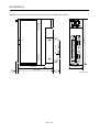
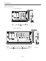
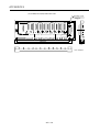
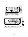
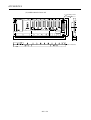
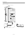
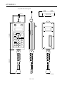
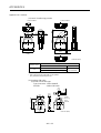
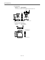
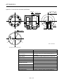
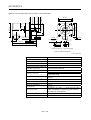
Appendix 2 Outside Dimensions.......................................................................................................APP-14
Appendix 2.1 CPU Modules ..........................................................................................................APP-14
Appendix 2.2 Pulse Generator/Synchronous Encoder Interface Module (A172SENC)................APP-16
Appendix 2.3 Main Base Unit........................................................................................................APP-17
Appendix 2.4 Extension Base Units..............................................................................................APP-19
Appendix 2.5 Teaching Unit..........................................................................................................APP-21
Appendix 2.6 Connector................................................................................................................APP-23
Appendix 2.7 Manual Pulse Generator Specifications..................................................................APP-25
Appendix 2.8 Serial Absolute Synchronous Encoder Specifications............................................APP-26

1. SPECIFICATIONS OF MOTION SYSTEM COMPONENTS
1
−
1
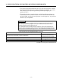
1. SPECIFICATIONS OF MOTION SYSTEM COMPONENTS
This chapter provides the system configuration of the motion system and the
specifications, functions, setting methods, external equipment connection
methods, part names and other information of the related modules for those who
are involved in the design, installation, wiring, trial run, adjustment and
maintenance of the motion system.
1.1 Overview of the Motion System
A173UHCPU/A172SHCPUN/A171SHCPUN are CPUs which incorporate the
positioning control CPU (hereinafter referred to as PCPU) and the sequence
control CPU (hereinafter referred to as SCPU) and perform the following functions:
•
PCPU..........Carries out the positioning control, home position return, servo
amplifier control status monitoring using a servo program or
motion program.
•
SCPU..........Carries out the sequence control, start-up of servo program or
motion program, enabling and disabling manual pulse generator
operation, and jog operation.
Positioning data setting and programming of A173UHCPU/A172SHCPUN/
A171SHCPUN is performed using the following peripheral devices and positioning
software package.
(1) Peripheral device
•
IBM PC/AT compatible running DOS/V5.0 or higher(hereinafter abbreviated
as "IBM PC")
(2) Positioning software package
•
For IBM PC .........SW
SRX-GSV
PE, SW
RN-GSV
PE
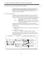
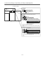
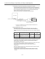
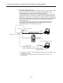
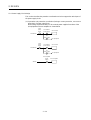
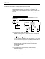
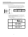
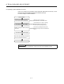
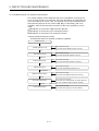
The following diagram outlines the peripheral devices and programs using a
positioning software package, data creation, and A173UHCPU/A172SHCPUN/
A171SHCPUN processing.
Sequence program
Servo program or
motion program
Positioning
parameter
SCPU
Positioning
device
PCPU
[Peripheral device] [Program, data] [A173UHCPU/A172SHCPUN/A171SHCPUN]
Sequence control
Servo program or motion
program execution
JOG operation
For communication
between SCPU and PCPU
Positioning control
Home position return
Servo monitoring
SW SRX-GSV PE,
SW RN-GSV PE
+
IBM PC
+
SW SRX-SV ,
SW RN-SV

1. SPECIFICATIONS OF MOTION SYSTEM COMPONENTS
1
−
2
•
The sequence program written into the SCPU, the servo program or motion
program written into the PCPU, and the positioning parameters are created
after starting up corresponding positioning software package by the
peripheral device.
•
The peripheral device started up by the positioning software package can
monitor the positioning control conditions of A173UHCPU/A172SHCPUN/
A171SHCPUN, execute the servo program or motion program, and perform a
test such as JOG operation.
REMARKS
For information about a peripheral device and programming information for
producing a sequence program and a special function unit, refer to each
manual pertaining to the individual unit.
For information about creating motion programs, refer to the programming
manual of the operating system used. For information about the operation of
each peripheral software package, refer to each individual operating manuals.
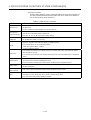
In this manual, the following abbreviations are used.
Description Abbreviation
A173UHCPU/A172SHCPUN/ A171SHCPUN Module
A173UHCPU/A172SHCPUN/
A171SHCPUN or CPU module
MR-H-BN,MR-J2S-B,MR-J2-B servo amplifier MR-H-BN/MR-J2S-B/MR-J2-B
A172SENC manual pulse generator/synchronous encoder interface unit/module A172SENC
Fast serial communication between motion controller and servo amplifier SSCNET
*1
*1 SSCNET: Servo System Controller NETwork

1. SPECIFICATIONS OF MOTION SYSTEM COMPONENTS
1
−
3
1.2 Overall Configuration of Motion System
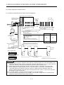
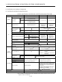
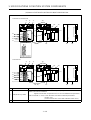
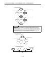
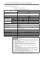
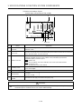
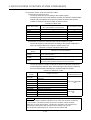
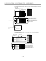
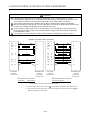
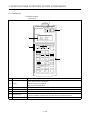
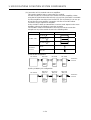
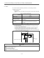
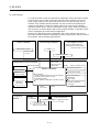
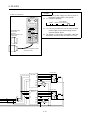
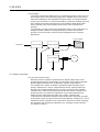
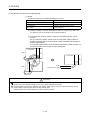
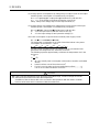
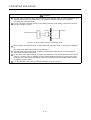
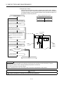
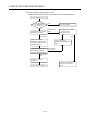
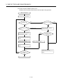
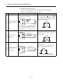
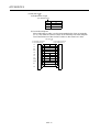
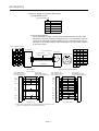
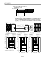
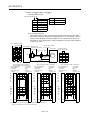
1.2.1 A172SHCPUN/A171SHCPUN System Overall Configuration
Motion slot Sequence module slot
Manual pulse generator/
synchronous encoder
interface module
Limit switch
output module
Battery
Emergency stop input
A1S input module or
special function module
Extension cable
(A1SC B for
A1S6 B
and A168B)
(A1S NB
for A6 B)
Power supply
module
Main base unit(A178B-S1/A17 B)
IBM PC
(DOS)
Manual pulse generator 1
(MR-HDP01)
Teaching unit
A31TU-E/A30TU-E
External input signals
SSC I/F card/board
(A30CD-PCF/A30BD-PCF)
Electromagnetic brake command output
SSCNET cable
Termination
resistance
A6BAT
100/200VAC
Motion CPU
A172
SENC
A1S
Y42
P
E
Serial absolute synchronous encoder cable
(MR-HSCBL M)
Serial absolute synchronous encoder 1
(MR-HENC)
TRA tracking
FLS upper stroke limit
RLS lower stroke limit
STOP signal
DOG/CHANGE near-zero point dog/
changeover between speed and position
8
1
RS422
RS422
IBM PC (DOS,Windows)
SSCNET2
SSCNET1
d1 d2 d3 dn
M
E
M
E
M
E
M
E
MR-H-BN/MR-J2S-B/MR-J2-B model
Servo amplifier
*2
*2:n:No. of control axes (max.)
A171SHCPUN 4
A172SHCPUN 8
A171SHCPUN A172SHCPUN
4
1
Sequence extension base
Up to one extension base unit for A1S6 B
Up to one extension base unit for A168B
(GOT compatible)
Up to one extension base unit for A6 B
GOT
*1
*1:No. of motion slots
A17 B 1
A178B-S1 2
Communication cable
(A270CDCBL M/
A270BDCBL M)
SSCNET:Servo System Controller NETwork
POINTS
(1) When using the sequence extension base and bus connection type GOT, select the A168B as the
sequence extension base. When not using the sequence extension base, you can connect the bus
connection type GOT directly to the extension connector of the main base unit.
(2) When using a teaching unit A31TU-E with a dead-man switch, a dedicated connecting cable
A31TUCBL03M is required between the CPU unit and A31TU-E connector. If the A31TU-E is
connected directly to the RS422 connector of the CPU without using a dedicated cable, the
A31TU-E will not operate at all. After disconnecting the A31TU-E, attach a short-circuit connector
A31SHORTCON for A31TUCBL.
(3) In a motion module, a sequence A1S I/O modules can also be installed.
(4) Though the external input signals of A172SENC are reserved for eight axes, for A171SHCPUN,
set those for the first half four axes (PX0 to PX0F).

1. SPECIFICATIONS OF MOTION SYSTEM COMPONENTS
1
−
4
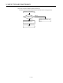
CAUTION
Configure safety circuits external to the controller or servo amplifier if their abnormal operation
could cause axis motion in a direction other than the safe operating direction for the system.
Ensure that the characteristics of other components used in a system match those of the
controllers, servo amplifiers, and servo motors.
Set the parameters to values appropriate for the controllers, servo amplifiers, servo motors,
regenerative resistor types, and system application. The protective functions may not work if the
parameters are set incorrectly.

1. SPECIFICATIONS OF MOTION SYSTEM COMPONENTS
1
−
5
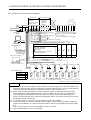
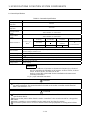
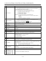
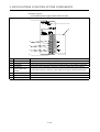
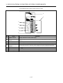
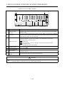
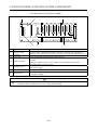
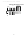
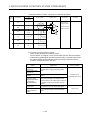
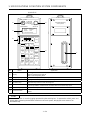
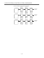
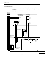
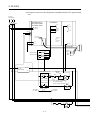
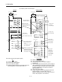
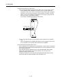
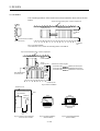
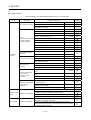
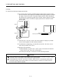
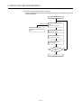
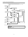
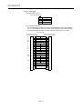
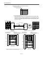
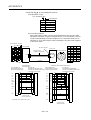
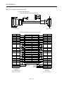
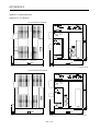
1.2.2 A173UHCPU System Overall Configuration
Motion slot Sequence module slot
Manual pulse
generator/
synchronous encoder
interface module
Battery
Emergency stop input
Power supply
module
Main base unit
(A178B-S3/
A178B-S2/
A178B-S1/
A17 B)
IBM PC
(DOS)
Manual pulse generator 3
(MR-HDP01)
Teaching unit
A31TU-E/A30TU-E
External input signals
SSC I/F card/board
(A30CD-PCF/A30BD-PCF)
Electromagnetic brake command output
SSCNET cable
A6BAT
100/200VAC
A173UHCPU
A172
SENC
P
E
Serial absolute synchronous
encoder cable
(MR-HSCBL M)
Serial absolute synchronous encoder 4
(MR-HENC)
TRA tracking
FLS upper stroke limit
RLS lower stroke limit
STOP signal
DOG/CHANGE near-zero point dog/
speed-position change
8
RS422
RS422
IBM PC (DOS,Windows)
SSCNET4
SSCNET1
d1
d8
M
E
M
E
MR-H-BN/MR-J2S-B/MR-J2-B model
Servo amplifier, max. 32 axes
1
Extension cable
(A1SC B for
A1S6 B
and A168B)
(A1S NB
for A6 B)
Sequence extension base
Up to one extension base unit for A1S6 B
Up to one extension base unit for A168B
(GOT compatible)
Up to one extension base unit for A6 B
GOT
*1
A172
SENC
A172
SENC
A172
SENC
A1S input module or
special function module
*1:No. of motion slots
A17 B 1
A178B-S1 2
A178B-S2 4
A178B-S3 8
*2
d9
d16
M
E
M
E
d17
d24
M
E
M
E
d25
d32
M
E
M
E
SSCNET2
SSCNET3
SSCNET4
*2
8 8 8
P
P
E
E
E
Communication cable
(A270CDCBL M/
A270BDCBL M)
1 1 1
*3
SSCNET:Servo S
y
stem Controller NETwork
POINTS
(1) When using the sequence extension base and bus connection type GOT, select the A168B as the
sequence extension base. When not using the sequence extension base, you can connect the bus
connection type GOT directly to the extension connector of the main base unit.
(2) When using a teaching unit A31TU-E with a dead-man switch, a dedicated connecting cable
A31TUCBL03M is required between the CPU unit and A31TU-E connector. If the A31TU-E is
connected directly to the RS422 connector of the CPU without using a dedicated cable, the
A31TU-E will not operate at all. After disconnecting the A31TU-E, attach a short-circuit connector
A31SHORTCON for A31TUCBL.
(3) In a motion module, a sequence A1S I/O modules can also be installed.
*2 The A173UHCPU can use four channels of the SSCNET. When using the SSCNET card/board
(A30CD-PCF/A30BD-PCF), connect it to the SSCNET4 and the servo amplifiers to the SSCNET1
to 3.
In this case, up to 24 axes of servo amplifiers can be connected.
*3 TRA tracking enable can use any one point.

1. SPECIFICATIONS OF MOTION SYSTEM COMPONENTS
1
−
6
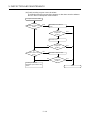
CAUTION
Configure safety circuits external to the controller or servo amplifier if their abnormal operation
could cause axis motion in a direction other than the safe operating direction for the system.
Ensure that the characteristics of other components used in a system match those of the
controllers, servo amplifiers, and servo motors.
Set the parameters to values appropriate for the controllers, servo amplifiers, servo motors,
regenerative resistor types, and system application. The protective functions may not work if the
parameters are set incorrectly.

1. SPECIFICATIONS OF MOTION SYSTEM COMPONENTS
1
−
7
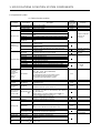
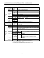
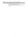
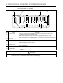
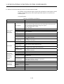
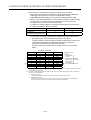
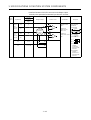
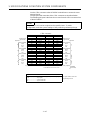
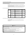
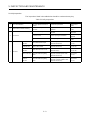
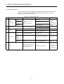
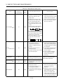
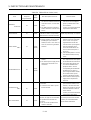
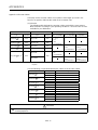
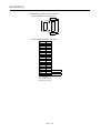
1.3 Equipment in System
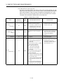
(1) Table of motion modules
Part Name Model Name Description
Current
Consumption
5 VDC (A)
Remarks
A173UHCPU(-S1) Max. 32 axes control 1.90
A172SHCPUN Max. 8 axes control 1.63CPU module
A171SHCPUN Max. 4 axes control 1.63
A172B One motion module slot and one sequence module slot
A175B One motion module slot and four sequence module slots
A178B
One motion module slot and seven sequence module
slots
A178B-S1 Two motion module slots and six sequence module slots
A178B-S2 Four motion module slots and four sequence module slots
Main base unit
A178B-S3
Eight motion module slots and zero sequence module
slots
Sequence extension
connector as
accessory
A1S65B
Extension power and five slots for system up to one
extension stage
A1S68B
Extension power and eight slots for system up to one
extension stage
Sequence
extension base
unit
A168B
Extension power and eight slots for system up to one
extension stage
Extension connector
as accessory
A1SC01B Flat cable of 55 mm (2.17 in) in length
For extension to the
right side
A1SC03B Length 330 mm (13 in)
A1SC07B Length 700 mm (27 in)
A1SC12B Length 1200 mm (47 in)
A1SC30B Length 3000 mm (118 in)
A1SC60B Length 6000 mm (236 in)
A1SC05NB Length 450 mm (17 in) AnN extension base cables
A1SC07NB Length 700 mm (27 in) AnN extension base cables
A1SC30NB Length 3000 mm (118 in) AnN extension base cables
Extension cable
A1SC50NB Length 5000 mm (197 in) AnN extension base cables
For A6 B
Manual pulse
generator
/synchronous
encoder
interface
module
A172SENC
32 points I/O signals
(FLS, RLS, STOP, DOG/CHANGE
×
8)
Tracking input 1 point
Electromagnetic brake control output 1 point
Manual pulse generator interface 1 point
Synchronous encoder interface 1 point
0.42
Limit output unit A1SY42 Transistor output 64 points, 12/24 VDC, 0.1A 0.93
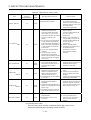
Manual pulse
generator
MR-HDP01
4.5 VDC to 13.2 VDC 25 PLS/rev, 100 PLS/rev at
magnification of 4
0.06
Serial absolute
synchronous
encoder
MR-HENC
Resolution: 16384 PLS/rev,
Permitted rotational speed: 4300r/min
0.15
Serial absolute
synchronous
encoder cable
MR-HSCBL
M
Synchronous encoder and A172SENC connector cables:
2 m (6.56 ft.), 5 m (16.4 ft.), 10 m (32.8 ft.), 20 m (65.6
ft.), 30 m (98.4 ft.)
(Same cables as encoder cables for HA-LH
K, HC-
SF/RF/UF(2000r/min)series motors.)
Battery A6BAT
For CPU module memory back-up
(Sequence program/servo program)
A30TU-E For SV13, cable length 5 m (16.4 ft) 0.22
A31TU-E
For SV13 with deadman switch, cable length 5 m (16.4
ft)
0.22
A31TU-RE
For SV51 with deadman switch, cable length 5 m (16.4
ft)
(Need A31TUCBL03M and A31SHORTCON.)
0.22
A31TUCBL03M CPU module to A31TU-E connector cable of 3 m (9.84 ft.) For control panel
Teaching unit
A31SHORTCON Short-circuit connector for A31TUCBL
When A31TU-E is
not connected
SSC I/F board A30BD-PCF ISA bus loading type, 2 channels/board
SSC I/F card A30CD-PCF PCMCIA TYPE II, 1 channel/card
SSC I/F board
cable
A270BDCBL
M
3 m (9.84 ft.), 5 m (16.4 ft.), 10 m (32.8 ft.) for
A30BD-PCF
SSC I/F card
cable
A270CDCBL
M
3 m (9.84 ft.), 5 m (16.4 ft.), 10 m (32.8 ft.) for
A30CD-PCF

1. SPECIFICATIONS OF MOTION SYSTEM COMPONENTS
1
−
8
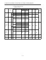
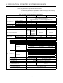
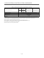
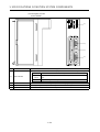
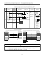
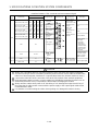
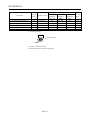
(2) Table of servo amplifier modules
Part Name Model Name Description
MR-H BN
50 W to 22 kW
Servo amplifier
MR-H
KBN
30 kW to 55 kW
Battery MR-BAT Backup for absolute position detection
Termination
connector
MR-TM Fitted to the last amplifier of SSCNET
MR-PB
External regenerative resistor 10 W to 500 W
MR-H
KB
Standard accessor
y
Regenerative power 600 W
MR-PB -4
External regenerative resistor 1300, 3900 W
FR-BU Brake unit 15/30/55K
Regenerative
resistor
FR-RC Power return converter 15/30/55K
SSCNET cable MR-HBUS
M
For connection of CPU module and MR-H-BN, for connection of MR-H-BN and
MR-H-BN
0.5 m(1.64 ft), 1 m (3.28ft), 5 m (16.4 ft)
MR-HSCBL M
Encoder cable
*2
MR-EN1CBL
M-H
For connection of HA-LH
K, HC-SF/RF/UF (2000r/min) series motor and MR-H-
BN
2 m (16.4 ft), 5 m (16.4 ft), 10 m (32.8 ft), 20 m (65.6 ft), 30 m (98.4 ft)
MR-JSCNS
MR-H-BN
series
Encoder
connector set
MR-EN1CNS
For
HA-LH
K, HC-SF/RF/UF (2000r/min) series motors
Amplifier side connector and encoder side connector set
MR-J2S- B
*1
50 W to 7 kW, three-phase 200 to 230 VAC or single-phase 230 VAC
MR-J2S-B
series
Servo amplifier
MR-J2S-
B1
50 W to 400 W, single-phase 100 to 120 VAC
MR-J2-B
series
Servo amplifier MR-J2-
B 50 W to 3.5 kW
Battery MR-BAT Backup for absolute position detection
Termination
connector
MR-A-TM Fitted to the last amplifier of SSCNET
MR-J2HBUS
M-A
For connection of CPU module and MR-J2S-B/MR-J2-B, for connection of MR-H-
BN and MR-J2S-B/MR-J2-B
0.5 m(1.64 ft), 1 m (3.28ft), 5 m (16.4 ft)
SSCNET cable
MR-J2HBUS
M
For connection of MR-J2S-B/MR-J2-B and MR-J2S-B/MR-J2-B
0.5 m(1.64 ft), 1 m (3.28ft), 5 m (16.4 ft)
MR-JHSCBL
M-L
Standard
cable
MR-JHSCBL
M-H
MR-ENCBL
M-H
Long flexing
life cable
For connection of HC-SFS/RFS/UFS (2000r/min) series motor and
MR-J2S-B, and for connection of HC-SF/RF/UF (2000r/min) series
motor and MR-J2-B
2 m (6.56 ft), 5 m (16.4 ft), 10 m (32.8 ft), 20 m (65.6 ft),
30 m (98.4 ft)
MR-JCCBL
M-L
Standard
cable
Encoder cable
*2
MR-JCCBL
M-H
Long flexing
life cable
For connection of HC-MFS/KFS/UFS (3000r/min) series motor and
MR-J2S-B, and for connection of HC-MF/UF (3000r/min), HA-FF
series motor and MR-J2-B
2 m (6.56 ft), 5 m (16.4 ft), 10 m (32.8 ft), 20 m (65.6 ft),
30 m (98.4 ft)
MR-J2CNS
MR-ENCNS
For HC-SF/RF/UF (2000r/min), HC-SFS/RFS/UFS (2000r/min) series motors
Amplifier side connector and encoder side connector set
Equipment
common to
MR-J2S-B
and
MR-J2-B
series
Encoder
connector set
MR-J2CNM
For HC-MF/UF (3000r/min), HA-FF, HC-MFS/KFS/UFS (3000r/min) series motors
Amplifier side connector and encoder side connector set
*1: 5kW and 7kW are scheduled for release.
*2: Long distance cable or cable without connector (cable only) is also available.
Avoid using a short cable as it will cause a position shift or the like.
Page is loading ...
Page is loading ...
Page is loading ...
Page is loading ...
Page is loading ...
Page is loading ...
Page is loading ...
Page is loading ...
Page is loading ...
Page is loading ...
Page is loading ...
Page is loading ...
Page is loading ...
Page is loading ...
Page is loading ...
Page is loading ...
Page is loading ...
Page is loading ...
Page is loading ...
Page is loading ...
Page is loading ...
Page is loading ...
Page is loading ...
Page is loading ...
Page is loading ...
Page is loading ...
Page is loading ...
Page is loading ...
Page is loading ...
Page is loading ...
Page is loading ...
Page is loading ...
Page is loading ...
Page is loading ...
Page is loading ...
Page is loading ...
Page is loading ...
Page is loading ...
Page is loading ...
Page is loading ...
Page is loading ...
Page is loading ...
Page is loading ...
Page is loading ...
Page is loading ...
Page is loading ...
Page is loading ...
Page is loading ...
Page is loading ...
Page is loading ...
Page is loading ...
Page is loading ...
Page is loading ...
Page is loading ...
Page is loading ...
Page is loading ...
Page is loading ...
Page is loading ...
Page is loading ...
Page is loading ...
Page is loading ...
Page is loading ...
Page is loading ...
Page is loading ...
Page is loading ...
Page is loading ...
Page is loading ...
Page is loading ...
Page is loading ...
Page is loading ...
Page is loading ...
Page is loading ...
Page is loading ...
Page is loading ...
Page is loading ...
Page is loading ...
Page is loading ...
Page is loading ...
Page is loading ...
Page is loading ...
Page is loading ...
Page is loading ...
Page is loading ...
Page is loading ...
Page is loading ...
Page is loading ...
Page is loading ...
Page is loading ...
Page is loading ...
Page is loading ...
Page is loading ...
Page is loading ...
Page is loading ...
Page is loading ...
Page is loading ...
Page is loading ...
Page is loading ...
Page is loading ...
Page is loading ...
Page is loading ...
Page is loading ...
Page is loading ...
Page is loading ...
Page is loading ...
Page is loading ...
Page is loading ...
Page is loading ...
Page is loading ...
Page is loading ...
Page is loading ...
Page is loading ...
Page is loading ...
Page is loading ...
Page is loading ...
Page is loading ...
Page is loading ...
Page is loading ...
Page is loading ...
Page is loading ...
Page is loading ...
Page is loading ...
Page is loading ...
Page is loading ...
Page is loading ...
Page is loading ...
Page is loading ...
Page is loading ...
Page is loading ...
Page is loading ...
Page is loading ...
Page is loading ...
Page is loading ...
Page is loading ...
Page is loading ...
Page is loading ...
Page is loading ...
Page is loading ...
Page is loading ...
Page is loading ...
Page is loading ...
Page is loading ...
-
 1
1
-
 2
2
-
 3
3
-
 4
4
-
 5
5
-
 6
6
-
 7
7
-
 8
8
-
 9
9
-
 10
10
-
 11
11
-
 12
12
-
 13
13
-
 14
14
-
 15
15
-
 16
16
-
 17
17
-
 18
18
-
 19
19
-
 20
20
-
 21
21
-
 22
22
-
 23
23
-
 24
24
-
 25
25
-
 26
26
-
 27
27
-
 28
28
-
 29
29
-
 30
30
-
 31
31
-
 32
32
-
 33
33
-
 34
34
-
 35
35
-
 36
36
-
 37
37
-
 38
38
-
 39
39
-
 40
40
-
 41
41
-
 42
42
-
 43
43
-
 44
44
-
 45
45
-
 46
46
-
 47
47
-
 48
48
-
 49
49
-
 50
50
-
 51
51
-
 52
52
-
 53
53
-
 54
54
-
 55
55
-
 56
56
-
 57
57
-
 58
58
-
 59
59
-
 60
60
-
 61
61
-
 62
62
-
 63
63
-
 64
64
-
 65
65
-
 66
66
-
 67
67
-
 68
68
-
 69
69
-
 70
70
-
 71
71
-
 72
72
-
 73
73
-
 74
74
-
 75
75
-
 76
76
-
 77
77
-
 78
78
-
 79
79
-
 80
80
-
 81
81
-
 82
82
-
 83
83
-
 84
84
-
 85
85
-
 86
86
-
 87
87
-
 88
88
-
 89
89
-
 90
90
-
 91
91
-
 92
92
-
 93
93
-
 94
94
-
 95
95
-
 96
96
-
 97
97
-
 98
98
-
 99
99
-
 100
100
-
 101
101
-
 102
102
-
 103
103
-
 104
104
-
 105
105
-
 106
106
-
 107
107
-
 108
108
-
 109
109
-
 110
110
-
 111
111
-
 112
112
-
 113
113
-
 114
114
-
 115
115
-
 116
116
-
 117
117
-
 118
118
-
 119
119
-
 120
120
-
 121
121
-
 122
122
-
 123
123
-
 124
124
-
 125
125
-
 126
126
-
 127
127
-
 128
128
-
 129
129
-
 130
130
-
 131
131
-
 132
132
-
 133
133
-
 134
134
-
 135
135
-
 136
136
-
 137
137
-
 138
138
-
 139
139
-
 140
140
-
 141
141
-
 142
142
-
 143
143
-
 144
144
-
 145
145
-
 146
146
-
 147
147
-
 148
148
-
 149
149
-
 150
150
-
 151
151
-
 152
152
-
 153
153
-
 154
154
-
 155
155
-
 156
156
-
 157
157
-
 158
158
-
 159
159
-
 160
160
-
 161
161


Mitsubishi Electric A171SHCPUN User manual
- Category
- Noise Reduction Machine
- Type
- User manual
- This manual is also suitable for
Ask a question and I''ll find the answer in the document
Finding information in a document is now easier with AI
Related papers
-
Mitsubishi Electric MELSEC-L LD77MS Simple Motion Module User manual
-
-
-
-
-
-
-
-
-
Other documents
-
 Mitsubishi Electronics Sleep Apnea Machine MR-MC211 User manual
-
Mitsubishi MELDAS MDS-C1 User manual
-
Weatherables WWR-THDW36-S6 Operating instructions
-
Mitsumi electronic Universal Remote IB-1500875(ENG)-E User manual
-
 Mitsubishi Electronics Car Amplifier MR-J2S- A User manual
-
 Mitsubishi Electronics MR-J2S- CL User manual
-
Furuno MR-J2S-A User manual
-
Speco AIPS03 User manual
-
Telex MR-J2S- B User manual
-
Hitachi HSC-2100 User manual


