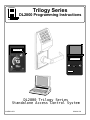
Alarm Lock Trilogy DL2800 Operating instructions
- Category
- Security access control systems
- Type
- Operating instructions
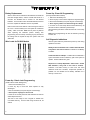
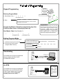
Alarm Lock Trilogy DL2800 is a standalone access control system that provides advanced security features for a wide range of applications. With its 200 user codes and 4 user groups, it offers flexible access control for your premises. The device's audit trail capability allows you to track all entries and program mode changes, ensuring a secure record of activities. The DL2800 also features programmable timeout functions, enabling you to temporarily disable users or enable passage mode for a specific duration without the need for manual intervention.
Alarm Lock Trilogy DL2800 is a standalone access control system that provides advanced security features for a wide range of applications. With its 200 user codes and 4 user groups, it offers flexible access control for your premises. The device's audit trail capability allows you to track all entries and program mode changes, ensuring a secure record of activities. The DL2800 also features programmable timeout functions, enabling you to temporarily disable users or enable passage mode for a specific duration without the need for manual intervention.


-
 1
1
-
 2
2
-
 3
3
-
 4
4
-
 5
5
-
 6
6
-
 7
7
-
 8
8
-
 9
9
-
 10
10
-
 11
11
-
 12
12
-
 13
13
-
 14
14
-
 15
15
-
 16
16
-
 17
17
-
 18
18
-
 19
19
-
 20
20
-
 21
21
-
 22
22
-
 23
23
-
 24
24
-
 25
25
-
 26
26
-
 27
27
-
 28
28


Alarm Lock Trilogy DL2800 Operating instructions
- Category
- Security access control systems
- Type
- Operating instructions
Alarm Lock Trilogy DL2800 is a standalone access control system that provides advanced security features for a wide range of applications. With its 200 user codes and 4 user groups, it offers flexible access control for your premises. The device's audit trail capability allows you to track all entries and program mode changes, ensuring a secure record of activities. The DL2800 also features programmable timeout functions, enabling you to temporarily disable users or enable passage mode for a specific duration without the need for manual intervention.
Ask a question and I''ll find the answer in the document
Finding information in a document is now easier with AI
Related papers
-
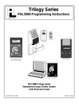
Alarm Lock Trilogy DL2800 Programming Instructions Manual
-
-
-
-
-
 Napco Security Systems AD8-PX4041 User manual
-
-
-
-

Other documents
-
LockeyUSA GE370 Operating instructions
-
MESA MRX1000E User guide
-
Tork DIN100A Operating Instructions Manual
-
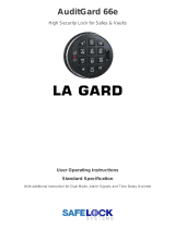 La Gard AuditGard 66e User Operating Instructions
-
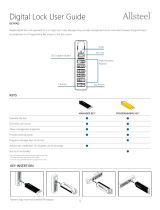 Allsteel Align Keypad Digital Lock User manual
-
 TURBOLOCK YL-99-BZ User manual
-
-
 OSI Security Devices OM300 User manual
-
Sargent Greenleaf 6123 Operating instructions
-


