Reliance Water Heaters ETC-10X User manual
- Type
- User manual

EXPANSION &
PUMP TANKS
n
Butyl diaphragm, for permanent separation
of air and water, with no waterlogging
n
In-line design, with
3
⁄4˝ NPTM Connection:
installs in cold water line of water heater
n
Maximum Working Pressure 150 PSI
n
Maximum Temperature: 140°F Residential
180°F Commercial
n
IAPMO Approved
n
5-Year Limited Warranty
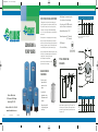
TYPICAL EXPANSION TANK
INSTALLATION
WHY EXPANSION TANKS ARE IMPORTANT
Thermal expansion occurs when water is heated during non-use
periods. The installation of a Pressure Reducing Valve (PRV), Check
Valve or Back Flow Preventer ˝closes˝ the water system, leaving
water with no room for expansion. National Standard Plumbing
code: 10.5.7 requires backflow prevention, to prevent backflow into
the water main.
Thermal expansion in a closed plumbing system can be damaging,
dangerous and costly. Its effects include damage to water heater
connections, gas water heater flue tubes, pumps serving washers and
dishwashers, leaking faucets, ˝weeping˝ of water through the water
heater T&P Safety Valve, and noisy water hammer in the pipes.
A properly sized Expansion Tank eliminates these problems, by giving
water a place to go when thermal expansion occurs. When a water
heating cycle ends, or when any fixture is opened
within the system, the impact of thermal
expansion is reduced, and water drains out of the
expansion tank back into the system.
RELIANCE EXPANSION
TANK FEATURES
n
Protection against
dangerous thermal
expansion in closed
systems
n
Steel shell with
polyurethane coating
for maximum corrosion
resistance
n
Drawn-steel tank with
2-coat bonded polymer
inner lining
Reliance Water Heaters
500 Tennessee Waltz Parkway
Ashland City, TN 37015
Reliance Hotline: 1-800-365-4054
www.reliancewaterheaters.com
Expansion Tank Sizing Chart For Residential Water Heaters
Water Heater Capacity in Gallons
Inlet Water
Pressure* 30 40 50 66 82 100
40 PSI ETC-2X ETC-2X ETC-2X ETC-5X ETC-5X ETC-5X
50 PSI ETC-2X ETC-2X ETC-2X ETC-5X ETC-5X ETC-5X
60 PSI ETC-2X ETC-2X ETC-5X ETC-5X ETC-5X ETC-5X
70 PSI ETC-2X ETC-2X ETC-5X ETC-5X ETC-5X ETC-5X
80 PSI ETC-2X ETC-5X ETC-5X ETC-5X ETC-5X ETC-5X
*Highest recorded inlet water pressure in a 24-hour period of
regulated water pressure.
Water Heater Expansion Tanks
Maximum Acceptable Dimensions
Volume (Gallons) in Inches Shipping
Gallon Weight
Model Number Capacity 40 PSI 60 PSI A B (Lbs.)
ETC-2X 1.96 1.27 1.03 8
3
⁄8 12
1
⁄2 5
ETC-5X 4.55 3.05 2.19 11
3
⁄8 14
3
⁄4 8
ETC-10X 9.21 6.55 5.25 15
3
⁄8 15
3
⁄4 20
All models: 150 PSIG Maximum Working Pressure
© 2007 November 2007R RPMCP00107
Expansion tanks are pre-charged with a 40 PSI air charge. If the
inlet water pressure is higher than 40 PSI,the expansion tank’s air
pressure must be adjusted to match that pressure but must not be
higher than 80 PSI.
A
B
186750_RPMCP00107 11/6/07 9:02 AM Page 1

WHY PUMP TANKS ARE IMPORTANT
A pump tank is an essential part of any well system, delivering
these benefits:
n
It ensures that your pump will run for at least one minute
each time it cycles, as required by pump manufacturers.
n
It stores a supplemental water supply between pump cycles,
to reduce the number of cycles throughout the day, and
helps prolong pump life.
n
It helps maintain water pressure within your system, ensuring
proper operation of your dishwasher and washing machine,
and robust flow for showering and bathing.
A properly sized pump and pump tank will work as a team to meet
your needs and will deliver many years of dependable service.
HOW TO SIZE A PUMP TANK
1.If you know your current pump size, use columns 2 and 3 in the
sizing chart to make your tank selection.
2.If you do not know your pump size or the size of your current
tank, count all your water fixtures. Be sure to include sinks,
tubs, showerheads, outside faucets, utility sinks, dishwasher,
washing machine, etc. Count each fixture individually. Use
columns 1 and 3 in the size chart to make your tank selection.
3.If replacing a glass-lined or other “standard” tank with a
diaphragm tank, use columns 3 and 4 in the size chart to
make your tank selection.
HOW A DIAPHRAGM PUMP TANK WORKS
1
28psi 35psi 50psi 35psi
35psi 50psi 35psi
234
HOW TO INSTALL A PUMP TANK
Each STA-CHARGED Pressurized Diaphragm Tank includes a
detailed, manual that takes you step-by-step through
installation procedures such as:
1. Determining proper tank location.
2. Attaching the acceptance fittings.
3. Adjusting the tank pre-charge pressure.
4. Leveling the tank and connecting it to
the water supply line.
5. Fine-tuning the tank to assure lag-free delivery.
TOOLS NEEDED FOR INSTALLATION
n
Screwdriver
n
Pipe Wrench
n
Hacksaw
n
Pliers
n
Teflon Tape
n
Pressure Gauge
(Tire Gauge)
SIZING CHART
1234
NUMBER OF ESTIMATED DIAPHRAGM “STANDARD”
WATER FIXTURES PUMP SIZE TANK MODELS TANK SIZES
UP TO 7 5-7 GPM* PMD-20, PMDH-20 42 GALLON
8-12 10 GPM* PMD-45 82 GALLON
13-16 12-15 GPM* PMD-65 120 GALLON
17-28 20 GPM* PMD-85, PMD-119 220 GALLON
*GPM = Gallons Per Minute
MODEL, ITEM, DIMENSIONS
& DRAWDOWN
Drawdown is the actual useable water a tank
can deliver during a cycle.
Drawdown will vary depending on the operating pressure range
set for your pump tank. Drawdown is a function of the tank volume.
Approximately 1/3rd of the tank total volume is usable water.
NOTE: The maximum working pressure is 100 PSI. Install a pressure
relief valve on every pump installation.
HORIZONTAL
A TYPICAL PUMP TANK INSTALLATION
REPLACING AN EXISTING PUMP TANK
A standard pump tank can be replaced with a diaphragm tank. This
will ensure operation of a maintenance-free system.
n
Install a pressure relief valve at the tank connection to ensure system
protection.
n
Be sure to plug the air port on a jet pump, since outside air is no
longer needed.
n
All open bleeder orafaces in the well casing must be plugged.
NOTE: A pressurized tank always takes up less space than a similar
capacity standard pump tank.
DIAPHRAGM PUMP TANKS
n
For dependable protection of your jet
or submersible well pump
n
Steel shell with powder-coated exterior
for maximum corrosion resistance
n
Metal air charge valve
is conveniently located and
resistant to mechanical damage
n
Strong butyl diaphragm delivers
dependable service
n
Epoxy-coated inner shell protects the water reservoir
IN-LINE
FREE STANDING
MODEL
VOL.
US GAL
DRAWDOWN
30-50 PSI
CONN SIZE
NPT
INCHES
A
INCHES
B
INCHES
C
INCHES
SHIPPING
WEIGHT
LBS
FREE STANDING PUMP TANKS
PMD-14 14 4.3 1 F 24 2 15 3/8 24
PMD-20 20 6.2 1 F 31 2 15 3/8 34
PMD-26 26 8.1 1 F 38 1/2 2 15 3/8 40
PMD-32 32 9.9 1 F 46 2 15 3/8 52
PMD-45 45 13.9 1 1/4 F 35 1/2 2 22 65
PMD-65 65 20.1 1 1/4 F 47 1/2 2 22 90
PMD-85 85 26.7 1 1/4 F 60 1/8 2 22 114
PMD-119 119 37.0 1 1/4 F 61 2 26 161
IN-LINE PUMP TANKS
PMDI-2 2 .6 3/4 M 12 1/2 – 8 3/8 4.5
PMDI-5 4.6 1.4 3/4 M 14 3/4 – 11 3/8 7.5
PMDI-7 7 2.3 3/4 M 18 7/8 – 11 3/8 11
PMDI-14 14 4.3 1 M 24 2 15 3/8 24
HORIZONTAL PUMP TANKS
PMDH-7 7 2.3 3/4 M 18 7/8 – 11 3/8 11
PMDH-14 14 4.3 1 M 20 – 15 3/8 24
PMDH-20 20 6.2 1 M 28 – 15 3/8 34
We also offer glass-lined tanks up to 120 gallons and galvanized tanks
up to 900 gallons. Please call 1-800-365-4054 for more information.
1. START-UP CYCLE
Diaphragm is pressed
against the bottom of
the chamber.
2. FILL CYCLE
Water is pumped
into the reservoir,
which forces the
diaphragm upward
into the air chamber.
3. HOLD CYCLE
Pump-cutoff pressure
is attained. Diaphragm
reaches its upmost position.
Reservoir is now filled to its
rated capacity.
4. DELIVERY CYCLE
Pump remains shut
off while air pressure
in top chamber
forces diaphragm
downward, delivering
water to the system.
186750_RPMCP00107 11/6/07 9:02 AM Page 6
-
 1
1
-
 2
2


Reliance Water Heaters ETC-10X User manual
- Type
- User manual
Ask a question and I''ll find the answer in the document
Finding information in a document is now easier with AI
Related papers
Other documents
-
Amtrol WELL-X-TROL User manual
-
Little GIANT 92061504 Specification
-
State SPMDI-2 Owner's manual
-
Matsui Dehumidifier PMD Series User manual
-
Watts HHS User guide
-
GSW Signature Series Electric User manual
-
Pentek ELECTRONICS Owner's manual
-
IDEAL INDUSTRIES H CXSi 180/H User manual
-
Pulsar Ultra 3 User manual
-
MYERS QD Series Owner's manual