Page is loading ...

For questions or help with this product contact Tech Support at (570) 546-9663 or techsupport@grizzly.com
MODEL T31725
LUMBER RACK
3-SHELF SYSTEM
INSTRUCTIONS
COPYRIGHT © SEPTEMBER, 2019 BY GRIZZLY INDUSTRIAL, INC.
NO PORTION OF THIS MANUAL MAY BE REPRODUCED IN ANY SHAPE
OR FORM WITHOUT THE WRITTEN APPROVAL OF GRIZZLY INDUSTRIAL, INC.
#CS20649 PRINTED IN CHINA
Find a location large enough to accompany the
material you wish to store. This storage system
must be secured to wall studs to support the load.
The storage system can be mounted to a vari-
ety of wall surfaces, including dry wall, masonry
walls, and steel-stud walls.
The assembled rack is 1
5
⁄8" thick and requires a
minimum anchor bolt size of 2
3
⁄4".
Note: The vertical bars can be used as a template
for pre-drilling holes prior to assembling the rack.
To install storage system:
1.
Locate small mounting hole
3
⁄8-inch from
bottom of vertical bar (see Figure 2).
2.
Thread (1) M5 x 16 tap screw fully into hole,
and slide a horizontal bar (with notch-side-
down) down vertical bar until it rests on screw
(see Figure 2).
Installing Storage System
V1.09.19
Introduction
The T31725 is a wall-mounted storage system
designed to organize your workshop. It can be
used for a variety of materials including lumber,
moldings, pipes, PVC, gutters, and more.
The T31725 provides 3 shelving levels. When
properly installed, each level has a maximum
weight capacity of up to 100 pounds. Always
ensure the rack is properly secured to the wall
by following all instructions. DO NOT exceed the
weight capacity listed.
Description Qty
A. Horizontal Bars ........................................... 6
B.
Vertical Bars ............................................... 2
C.
Tap Screws M5 x 16 ................................... 8
D.
Spacers
1
⁄4" x 1
1
⁄4" x
1
⁄2 ................................ 4
Inventory
Figure 1. Inventory components.
A
B
C
D
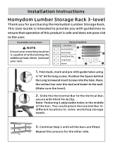
Figure 2. Horizontal bar sliding into place.
Notch
Screw

-2-
T31725 Lumber Rack (Mfd. 09/19)
3. Repeat Steps 1–2 for remaining pre-drilled
mounting holes on both vertical bars, working
your way up from bottom to top.
Note: To customize horizontal bar height, drill
3
⁄32" holes for mounting M5 x 16 tap screw to
vertical bars at desired height.
4.
Locate a suitable wall mounting position,
ensuring each vertical bar will be centered on
a support stud.
Note: The weight capacity is rated for a
recommended distance of 4–6 feet between
each vertical bar (see Figure 3). For longer
materials, additional wood racks may be
required.
5.
Place spacers behind each mounting hole (2
holes per vertical bar, see Figure 4), and fas-
ten through wall and into a stud with appropri-
ate mounting fastener (not included).
Figure 3. Recommended space between vertical
bars.
4 – 6 Feet
Figure 4. Mounting wood rack to wall.
Figure 6. Fully assembled wood rack.
Material Stop Holes
A small material stop may be placed at the end of
each horizontal bar to prevent material from slid-
ing off the rack.
Place a bolt (not included) through the hole with
threads pointing up (see Figure 5). Secure with a
washer and nut (not included).
Figure 5. Material stop placed on horizontal bar.
Spacer
Only secure vertical bars directly into wall
studs. Failure to do so will decrease rack
load capacity and could lead to rack failure,
resulting in personal injury or property
damage.
/