
CATALOG NO. 3400.53A
Effective: 8-1-06
Replaces: 6-15-06
P/N 241288 Rev 2
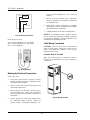
INSTALLATION
AND OPERATING
INSTRUCTIONS
Models 503-2003
Types H & WH
FOR YOUR SAFETY
Do not store or use gasoline or other flammable vapors and liquids or other combustible materials in the vicinity of
this or any other appliance. To do so may result in an explosion or fire.
WARNING
Improper installation, adjustment, alteration, service or maintenance can cause property damage, personal injury,
exposure to hazardous materials* or loss of life. Review the information in this manual carefully. Installation and
service must be performed by a qualified installer, service agency or the gas supplier.
* This unit contains materials that have been identified as carcinogenic, or possibly carcinogenic, to humans.
WHAT TO DO IF YOU SMELL GAS
• Do not try to light any appliance.
• Do not touch any electrical switch; do not use any phone in your building.
• Immediately call your gas supplier from a neighbor’s phone. Follow the gas supplier’s instructions.
• If you cannot reach your gas supplier, call the fire department.
This manual should be maintained in legible condition and kept adjacent to the heater or in a safe place for future
reference.


1
WARNINGS................................................................2
SECTION A Before Installation ..............................3
Product Receipt .......................................................3
Model Identification................................................3
Ratings and Certifications........................................3
Installations at Elevation .........................................4
Component Locations..............................................4
General Information ................................................4
SECTION B Hot Water Supply General Safety.....5
Time/Temperature Relationships in Scalds.............6
SECTION C Installation...........................................7
Installation Codes....................................................7
Equipment Base.......................................................7
Clearances................................................................7
Combustion and Ventilation Air..............................9
Water Piping..........................................................11
Gas Supply.............................................................17
Electrical Power Connections................................19
Venting..................................................................21
Controls.................................................................28
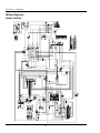
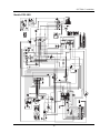
Wiring Diagrams...................................................38
SECTION D Start-up..............................................41
Pre Start-up............................................................41
Start-Up.................................................................42
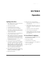
SECTION E Operation...........................................47
Lighting Instructions .............................................47
To Turn Off Gas To Appliance .............................47
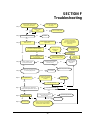
SECTION F Troubleshooting .................................49
UDB Fault History ................................................50
SECTION G Maintenance......................................51
Suggested Minimum Maintenance Schedule.........51
Preventive Maintenance Schedule.........................52
SECTION H Appendix...........................................53
Inside Air Contamination......................................53
Table of Contents

2
PAY ATTENTION TO THESE TERMS:
DANGER:
Indicates the presence of immediate hazards which will cause severe personal injury,
death or substantial property damage if ignored.
WARNING:
Indicates the presence of hazards or unsafe practices which could cause severe personal
injury, death or substantial property damage if ignored.
CAUTION:
Indicates the presence of hazards or unsafe practices which could cause minor personal
injury or product or property damage if ignored.
NOTICE:
Indicates special instructions on installation, operation, or maintenance which are impor-
tant but not related to personal injury hazards.
DANGER: Make sure the gas on which the
heater will operate is the same type as that
specified on the heater rating plate.
WARNING: Should overheating occur or the
gas supply valve fail to shut, do not turn off or
disconnect the electrical supply to the heater.
Instead, shut off the gas supply at a location
external to the heater.
WARNING: Do not use this heater if any part
has been under water. Immediately call a
qualified service technician to inspect the
heater and to replace any part of the control
system and any gas control which has been
under water.
WARNING: To minimize the possibility of
improper operation, serious personal injury,
fire, or damage to the heater:
• Always keep the area around the heater
free of combustible materials, gasoline,
and other flammable liquids and vapors.
• Heater should never be covered or have
any blockage to the flow of fresh air to the
heater.
WARNING: Risk of electrical shock. More
than one disconnect switch may be required to
de-energize the equipment before servicing.
WARNING - CALIFORNIA PROPOSI-
TION 65: This product contains chemicals
known to the State of California to cause can-
cer, birth defects or other reproductive harm.
CAUTION: Operation of this heater in low-
temperature systems requires special piping.
Harmful internal condensation will occur if
the inlet water temperature does not exceed
105°F. Warranty claims will be denied when
condensation occurs.
CAUTION: If this heater is to be installed
above radiation level, it must be provided with
a low water cut-off device at the time of heater
installation.
CAUTION: This heater requires forced water
circulation when the burner is operating. See
minimum and maximum flow rates. Severe
damage will occur if the heater is operated
without proper water flow circulation.
CAUTION: If this heater is to be installed in
a negative or positive pressure equipment
room, there are special installation require-
ments. Consult factory for details.
WARNINGS

SECTION C: Installation
3
Raypak strongly recommends that this manual be re-
viewed thoroughly before installing your MVB heater.
Please review the General Safety information in Sec-
tion B before installing the heater. Factory warranty
does not apply to heaters that have been improperly
installed or operated. (Refer to the warranty at the back
of this manual.) Installation and service must be per-
formed by a qualified installer, service agency or gas
supplier. If, after reviewing this manual, you still have
questions which this manual does not answer, please
contact the manufacturer or your local Raypak repre-
sentative.
Thank you for purchasing a Raypak product. We hope
you will be satisfied with the high quality and durabil-
ity of our equipment.
Product Receipt
On receipt of your heater it is suggested that you visu-
ally check for external damage to the shipping crate. If
the crate is damaged, make a note to that effect on the
Bill of Lading when signing for the shipment. Remove
the heater from the shipping packaging. Report any
damage to the carrier immediately.
On occasion, items are shipped loose. Be sure that you
receive the correct number of packages as indicated on
the Bill of Lading.
Claims for shortages and damages must be filed with
the carrier by consignee. Permission to return goods
must be received from the factory prior to shipping.
Goods returned to the factory without an authorized
Returned Goods Receipt number will not be accepted.
All returned goods are subject to a restocking charge.
When ordering parts, you must specify the model and
serial numbers of the heater. When ordering under war-
ranty conditions, you must also specify the date of
installation.
Purchased parts are subject to replacement only under
the manufacturer’s warranty. Debits for defective re-
placement parts will not be accepted and will be
replaced in kind only per Raypak’s standard warranties.
Model Identification
The model identification number and heater serial
number are found on the heater rating plate located on
the upper rear jacket panel of the heater. The model
number will have the form H7-2003 or similar
depending on the heater size and configuration. The
letter(s) in the first group of characters identifies the
application (H = Hydronic Heating, WH = Domestic
Hot Water (DHW)). The number which follows identi-
fies the firing mode (7 = electronic modulation). The
second group of characters identifies the size of the
heater (three or four numbers representing the ap-
proximate MBTUH input), and, where applicable, a
letter, indicating the manufacturing series.
Ratings and Certifications
Standards:
• ANSI Z21.13 · CSA 4.9 - latest edition, Gas-Fired
Hot Water Boilers
• CAN 3.1 - latest edition, Industrial and Commercial
Gas-Fired Package Boilers
• ANSI Z21.10.3 · CSA 4.3 - latest edition, Gas Wa-
ter Heaters
• SCAQMD Rule 1146.2
SECTION A
Before Installation

SECTION A: Before Installation
4
All Raypak heaters are National Board Approved, and
design-certified and tested by the Canadian Standards
Association (CSA) for the U.S. and Canada. Each heater
is constructed in accordance with Section IV of the
American Society of Mechanical Engineers (ASME)
Heater Pressure Vessel Code and bears the ASME stamp.
The heater also complies with the latest edition of
ASHRAE 90.1 Standard.
WARNING: Altering any Raypak pressure vessel by
installing replacement heat exchangers, tube bundle head-
ers, or any ASME parts not manufactured and/or approved
by Raypak will instantly void the ASME and CSA ratings
of the vessel and any Raypak warranty on the vessel. Al-
tering the ASME or CSA ratings of the vessel also
violates national, state, and local approval codes.
Installations at Elevation
Rated inputs are suitable for up to 4,500 ft elevation with-
out de-rating. Consult the factory for installations at
altitudes over 4,500 ft above sea level. No hardware
changes are required to the heaters for installations up to
10,000 ft (adjustments may be required).
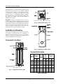
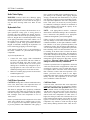
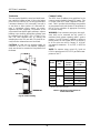
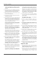
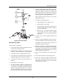
Component Locations
Panels omitted for clarity
Fig. 1: Component Locations - Side
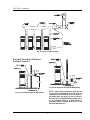
Top panel, blower and gas train omitted for clarity
Fig. 2: Component Locations - Top
Fig. 3: Component Locations – Rear
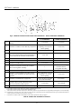
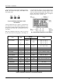
General Information
MBTUH
Input
Gas
Conn.
(NPT)
Vent Size
(in.)
Model
No.
Max. Min.
Water
Conn.
(NPT)
N P Flue Intake
503 500 125 2 1 1 6 6
753 750 188 2 1 1 6 6
1003 999 250 2-1/2 1-1/4 1 6 6
1253 1250 312 2-1/2 1-1/4 1 8 8
1503 1500 375 2-1/2 1-1/4 1 8 8
1753 1750 438 2-1/2 2 1 8 8
2003 1999 500 2-1/2 2 1 8 8
Table A: Basic Data

SECTION C: Installation
5
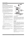
To meet commercial hot water use needs, the high limit
safety control on this water heater is adjustable up to
210°F. However, water temperatures over 125°F can
cause instant severe burns or death from scalds. When
supplying general purpose hot water, the recommended
initial setting for the control is 125°F.
Safety and energy conservation are factors to be con-
sidered when setting the water temperature on the
thermostat. The most energy-efficient operation will
result when the temperature setting is the lowest that
satisfies the needs of the application.
Water temperature over 125°F can cause instant severe
burns or death from scalds. Children, disabled and eld-
erly are at highest risk of being scalded.
• Feel water before bathing or showering.
• Temperature limiting valves are available.
NOTE: When this water heater is supplying general
purpose hot water for use by individuals, a thermostati-
cally controlled mixing valve for reducing point of use
water temperature is recommended to reduce the risk
of scald injury. Contact a licensed plumber or the local
plumbing authority for further information.
Maximum water temperatures occur just after the
heater’s burner has shut off. To determine the water
temperature being delivered, turn on a hot water faucet,
place a thermometer in the hot water stream and read
the thermometer.
This section applies to Hot Water Supply Boilers and
Hot Water Heaters ONLY. For sanitary rinse applica-
tions where outlet temperatures of 180°F to 195°F are
required, a boiler is recommended since the 210°F limit
on water heaters will NOT allow the heater to maintain
these desired sanitary rinse temperatures.
Water temperature over 125°F can
cause instant severe burns or death
from scalds.
Children, disabled, and elderly are
at highest risk of being scalded.
See instruction manual before set-
ting temperature at water heater.
Feel water before bathing or show-
ering.
Temperature limiting valves are
available, see manual.
SECTION B
Hot Water Supply
General Safety

SECTION B: General Safety
6
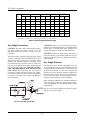
Time/Temperature Relationships
in Scalds
The following chart details the relationship of water
temperature and time with regard to scald injury and
may be used as a guide in determining the safest water
temperature for your applications.
Water Temp. Time to Produce Serious Burn
120°F More than 5 minutes
125°F 1-1/2 to 2 minutes
130°F About 30 seconds
135°F About 10 seconds
140°F Less than 5 seconds
145°F Less than 3 seconds
150°F About 1-1/2 seconds
155°F About 1 second
Table courtesy of The Shriners Burn Institute
Table B: Time to Produce Serious Burn
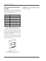
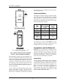
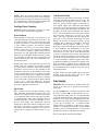
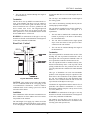
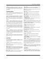
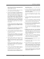
The temperature of the water in the heater can be regu-
lated by using the Raypak Modulating Temperature
Control. To comply with safety regulations, the control
is set at 120°F when shipped from the factory (Mode 3
default setting for Tank Target).
To adjust the water temperature, follow the instruction
for the operation of the control starting on page 28 of
this manual. The control is shown below for identifica-
tion purposes only. (See Fig. 4.)
Fig. 4: Modulating Temperature Control
CAUTION: Hotter water increases the risk of scald-
ing! There is a hot water scald potential if the
thermostat is set too high.

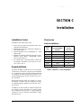
SECTION C: Installation
7
Installation Codes
Installations must follow these codes:
• Local, state, provincial, and national codes, laws,
regulations and ordinances
• National Fuel Gas Code, ANSI Z223.1/NFPA 54 –
latest edition (NFGC)
• National Electrical Code, ANSI/NFPA 70 - latest
edition (NEC)
• Standard for Controls and Safety Devices for Auto-
matically Fired Boilers, ANSI/ASME CSD-1,
(CSD-1) when required
• For Canada only: CAN/CSA B149.1 Natural Gas
and Propane Installation Code and CSA C22.1
C.E.C. Part 1 (C22.1)
Equipment Base
The heater should be mounted on a level, structurally
sound surface. The heater is approved for installation
on a combustible surface but must NEVER be installed
on carpeting. Gas-fueled equipment installed in en-
closed parking garages must be located at least 18 in.
above the floor.
When such locations cannot be avoided, it is recom-
mended that a suitable catch pan, adequately drained,
be installed under the appliance. The pan must not re-
strict air flow.
In addition, the heater shall be installed such that the
gas ignition system components are protected from
water (dripping, spraying, rain, etc.) during appliance
operation or service (circulator replacement, control
replacement, etc.).
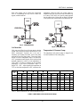
Clearances
Indoor Installations
Heater
Side
Minimum Clearance
from Combustible
Surfaces
Recommended
Service
Clearance
Floor* 0” 0”
Rear 12” 24”
Right Side 1” 1”
Left Side 1” 1”
Top 0” 10”
Front Open 24”
Vent 1” 1”
* DO NOT install on carpeting.
Table C: Clearances – Indoor Installations
SECTION C
Installation

SECTION C: Installation
8
Fig. 5: Minimum Clearances from Vent/Air Inlet Terminations – Indoor and Outdoor Installations
U.S. Installations
1
Canadian Installations
2
A
Clearance above grade, veranda, porch, deck, or
balcony
1 ft (30 cm) 1 ft (30 cm)
B Clearance to window or door that may be opened
4 ft (1.2m) below or to side
of opening; 1 foot (30 cm)
above opening
3 ft (91 cm)
C Clearance to permanently closed window
* *
D
Vertical clearance to ventilated soffit located
above the terminal within a horizontal distance of
2 ft (61cm) from the centerline of the terminal
5 ft (1.5m)
*
E Clearance to unventilated soffit
* *
F Clearance to outside corner
* *
G Clearance to inside corner 6 ft (1.83m)
*
H
Clearance to each side of center line extended
above meter/regulator assembly
*
3 ft (91 cm) within a height
15 ft above the me-
ter/regulator assembly
I Clearance to service regulator vent outlet
*
6 ft (1.83m)
J
Clearance to non-mechanical air supply inlet to
building or the combustion air inlet to any other
appliance
4 ft (1.2m) below or to side
of opening; 1 ft (30 cm)
above opening
3 ft (91 cm)
K Clearance to mechanical air supply inlet
3 ft (91 cm) above if within
10 ft (3m) horizontally
6 ft (1.83m)
L
Clearance above paved sidewalk or paved
driveway located on public property
7 ft (2.13m)
7 ft (2.13m) t
M Clearance under veranda, porch, deck or balcony
*
12 in. (30 cm) TT
1
In accordance with the current ANSI Z223.1/NFPA 54 National Fuel Gas Code
2
In accordance with the current CAN/CGA-B149 Installation Codes
t Vent terminal shall not terminate directly above sidewalk or paved driveway located between 2 single family dwellings that serves both dwellings
TT Permitted only if veranda, porch, deck, or balcony is fully open on a minimum of two sides beneath the floor and top of terminal and underside of
veranda, porch, deck or balcony is greater than 1 ft (30cm)
* Clearances in accordance with local installation codes and the requirements of the gas supplier
Table D: Vent/Air Inlet Termination Clearances

SECTION C: Installation
9
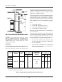
Venting not shown for clarity. Heater must be vented
per instructions in this manual
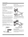
Fig. 6: Minimum Clearances from Combustible
Surfaces – Indoor and Outdoor Installations
When installed according to the listed minimum clear-
ances from combustible construction, these heaters can
still be serviced without removing permanent structural
construction around the heater. However, for ease of
servicing, we recommend a clearance of at least 24 in.
in front, at least 24 in. on the rear and 10 in. above the
top of the heater. This will allow the heater to be ser-
viced in its installed location without movement or
removal of the heater.
Service clearances less than the minimum may require
removal of the heater to service either the heat ex-
changer or the burner components. In either case, the
heater must be installed in a manner that will enable
the heater to be serviced without removing any struc-
ture around the heater.
Outdoor Installations
These heaters are design-certified for outdoor installa-
tion. Heaters must not be installed under an overhang
that is less than 3 ft from the top of the vent terminal.
Three sides must be open in the area under the over-
hang. Roof water drainage must be diverted away from
heaters installed under overhangs.
Heater
Side
Min. Clearance
from Combustible
Surfaces
Recommended
Service
Clearance
Rear 12” 24”
Right Side 1” 1”
Left Side 1” 1”
Top Unobstructed Unobstructed
Vent
Termination
12” 12”
Table E: Clearances – Outdoor Installations
The combustion air intake terminal MUST be used for
outdoor installations. The hood is shipped loose and
installed on the rear of the heater at the jobsite.
Combustion and Ventilation Air
NOTICE: Use of the heater in construction areas
where fine particulate matter, such as concrete or dry-
wall dust, is present may result in damage to the burner
that is not covered by the warranty. If operated in a
construction environment, a clean source of combus-
tion air must be provided directly to the heater.
Indoor Units
The heater must be supplied with sufficient quantities
of non-contaminated air to support proper combustion
and equipment ventilation. Combustion air can be sup-
plied via conventional means where combustion air is
drawn from the area immediately surrounding the
heater, or via direct vent, where combustion air is
drawn directly from outside. All installations must
comply with the requirements of the NFGC (U.S.) and
B149.1 (Canada), and all local codes.

SECTION C: Installation
10
CAUTION: Combustion air must not be contaminated
by corrosive chemical fumes which can damage the
heater and void the warranty. (See Section H.)
NOTICE: It is recommended that the intake vent be
insulated to minimize sweating.
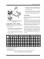
Optional Construction Air Filter
An optional construction air filter is available for use.
The filter should be removed after construction is fin-
ished to allow for unrestricted air flow to the heater.
Direct Vent
If outside air is drawn through the intake pipe directly
to the unit for combustion:
1. Install combustion air direct vent in accordance
with Fig. 24 (horizontal) or Fig. 25 (vertical) of
this manual (pages 26 & 27 respectively).
2. Provide adequate ventilation of the space occupied
by the heater(s) by an opening(s) for ventilation air
at the highest practical point communicating with
the outdoors. The total cross-sectional area shall be
at least 1 in.
2
of free area per 20,000 BTUH (111
mm
2
per kW) of total input rating of all equipment
in the room when the opening is communicating
directly with the outdoors or through vertical
duct(s). The total cross-sectional area shall be at
least 1 in.
2
of free area per 10,000 BTUH (222
mm
2
per kW) of total input rating of all equipment
in the room when the opening is communicating
with the outdoors through horizontal duct(s).
3. In cold climates, and to mitigate potential freeze-
up, Raypak highly recommends the installation of
a motorized sealed damper to prevent the circula-
tion of cold air through the heater during non-
operating hours.
TruSeal™ Combustion Air
In addition to the 3 previous steps, combustion air may
be ducted directly to the heater by using PVC, CPVC
or sealed single-wall galvanized ducting. The duct will
attach directly to the air collar located on the rear of the
heater, using three or four sheet metal screws (not sup-
plied) equally positioned around the circumference of
the duct. The screen assembly should be removed be-
fore attaching any air duct to the heater. The screws
and duct connection point must be sealed with RTV
(not supplied). TruSeal is generally used when damag-
ing contaminants are present in the mechanical room.
All ducting should be self-supported.
CAUTION: Use TruSeal combustion air if damaging
airborne contaminants are or may be present in the
heater area. See Section H of this manual regarding air
contamination.
Conventional Combustion Air Supply
U.S. Installations
All Air from Inside the Building
The confined space shall be provided with TWO per-
manent openings communicating directly with an
additional room(s) of sufficient volume so that the
combined volume of all spaces meets the criteria for a
room large in comparison (NFGC). The total input of
all gas utilization equipment installed in the combined
space shall be considered in making this determination.
Each opening shall have a minimum free area of 1 in.
2
per 1,000 BTUH (2,225 mm
2
per kW) of the total input
rating of all gas utilization equipment in the confined
space, but not less than 100 in.
2
(645 cm
2
). One open-
ing shall commence within 12 in. (305 mm) of the top,
and one opening shall commence within 12 in. (305
mm) of the bottom of the enclosure. The minimum
dimension of air openings shall be not less than 3 in.
(76 mm) in any direction.
All Air from Outdoors
The confined space shall communicate with the out-
doors in accordance with one of the methods below.
The minimum dimension of air openings shall not be
less than 3 in. (76 mm) in any direction. Where ducts
are used, they shall be at least of the same cross-
sectional area as the net free area of the openings to
which they connect.
1. Two permanent openings, one commencing
within 12 in. (305 mm) of the top, and one com-
mencing within 12 in. (305 mm) of the bottom of
the enclosure, shall be provided. The openings
shall communicate directly, or by ducts, with the
outdoors or spaces (crawl or attic) that freely
communicate with the outdoors.
a. Where directly communicating with the out-
doors or where communicating to the outdoors
through vertical ducts, each opening shall
have a minimum free area of 1 in.
2
per 4,000
BTUH (550 mm
2
per kW) of total input rating
of all equipment in the enclosure.

SECTION C: Installation
11
b. Where communicating with the outdoors
through horizontal ducts, each opening shall
have a minimum free area of 1 in.
2
per 2,000
BTUH (1,100 mm
2
per kW) of total input rat-
ing of all equipment in the enclosure.
2. One permanent opening, commencing within 12
in. (305 mm) of the top of the enclosure, shall be
permitted where the equipment has clearances of at
least 1 in. (25 mm) from the sides and back and 6
in. (152 mm) from the front of the appliance. The
opening shall directly communicate with the out-
doors or shall communicate through a vertical or
horizontal duct to the outdoors or spaces that
freely communicate with the outdoors, and shall
have a minimum free area of:
a. 1 in.
2
per 3,000 BTUH (740 mm
2
per kW) of
the total input rating of all equipment located
in the enclosure, and
b. Not less than the sum of the areas of all vent
connectors in the confined space.
WARNING: Do not use the “one permanent opening”
method if the equipment room may be under negative
pressure conditions.
Canadian Installations
CAUTION: All combustion air must be drawn from
the air outside of the building; the mechanical equip-
ment room must communicate directly with the
outdoors.
1. Ventilation of the space occupied by the heater
shall be provided by an opening(s) for ventilation
air at the highest practical point communicating
with the outdoors. The total cross-sectional area of
such an opening(s) shall be at least 10% of the area
required in 2. and 3. (below), but in no case shall
the cross-sectional area be less than 10 in.
2
(65
cm
2
).
2. For heaters using a barometric damper in the vent
system there shall be a permanent air supply open-
ing(s) having a cross section area of not less than 1
in.
2
per 7,000 BTUH (320 mm
2
per kW) up to and
including 1 million BTUH, plus 1 in.
2
per 14,000
BTUH (160 mm
2
per kW) in excess of 1 million
BTUH. This opening(s) shall be either located at
or ducted to a point not more than 18 in. (450 mm)
nor less than 6 in. (152 mm) above the floor level.
The duct can also “goose neck” through the roof.
The duct is preferred to be straight down and ter-
minated 18 in. (450 mm) from the floor, but not
near piping. This air supply opening requirement
shall be in addition to the air opening for ventila-
tion air required in 1. (above).
WARNING: Care must be taken to ensure that the
equipment room is not under negative pressure
conditions.
3. For heaters not using a barometric damper in the
vent system, and when air supply is provided by
natural air flow from outdoors for a power burner
and there is no draft regulator, drafthood or similar
flue gas dilution device installed in the same space,
in addition to the opening for ventilation air re-
quired in 1., there shall be a permanent air supply
opening(s) having a total cross-sectional area of
not less than 1 in.
2
for each 30,000 BTUH (74
mm
2
per kW) of total rated input of the burner(s),
and the location of the opening(s) shall not inter-
fere with the intended purpose of the opening(s)
for ventilation air referred to in 1. This opening(s)
can be ducted to a point not more than 18 in. (450
mm) nor less than 6 in. (152 mm) above the floor
level. The duct can also “goose neck” through the
roof. The duct is preferred to be straight down 18
in. (450 mm) from the floor, but not near piping.
4. Refer to B149.1 for additional information.
Water Piping
General
The heater should be located so that any water leaks
will not cause damage to the adjacent area or structures.
CAUTION: This heater requires forced water circula-
tion when the burner is operating. See Table F for
minimum and maximum flow rates for water pump
selection. The pump should be interlocked with the
heater to prevent heater operation without water circu-
lation.
NOTICE: Minimum pipe size for in/out connections is
2 in. NPT for 503 and 753 models and 2-½ in NPT for
1003 – 2003 models. Verify proper flow rates and ∆T
as instructed in this manual.

SECTION C: Installation
12
Relief Valve Piping
WARNING: Pressure relief valve discharge piping
must be piped near the floor and close to a drain to
eliminate the potential of severe burns. Do not pipe to
any area where freezing could occur. Refer to local
codes.
Hydrostatic Test
Unlike many types of heaters, this heater does not re-
quire hydrostatic testing prior to being placed in
operation. The heat exchanger has already been fac-
tory-tested and is rated for 160 psi operating pressure.
However, Raypak does recommend hydrostatic testing
of the piping connections to the heater and the rest of
the system prior to operation. This is particularly true
for hydronic systems using glycol-based antifreeze.
Raypak recommends conducting the hydrostatic test
before connecting gas piping or electrical supply.
Leaks must be repaired at once to prevent damage to
the heater. NEVER use petroleum-based stop-leak
compounds.
To perform hydrostatic test:
1. Connect fill water supply. With field-installed
bleed valve open, fill heater with water. When wa-
ter flows from bleed valve, shut off water. Close
bleed valve. Carefully fill the rest of the system,
making sure to eliminate any entrapped air by us-
ing high-point air vents. Close feed valve. Test at
standard operating pressure for at least 24 hours.
2. Make sure constant gauge pressure has been main-
tained throughout test.
3. Check for leaks. Repair if found.
Cold Water Operation
CAUTION: Damage due to internal condensation may
occur if the heater inlet water temperature does not
exceed 120˚F (49ºC) within 7 minutes of start-up.
This heater is equipped with a proprietary condensate
evaporation system which will evaporate any conden-
sate that may begin to accumulate inside the primary
heat exchanger with water temperatures as low as
120ºF (49ºC).
Heaters operated with an inlet temperature of less than
120ºF (49ºC) MUST have a manual bypass (see Fig.
14) or an approved low-temperature operation system
to prevent problems with condensation. This piping is
like a primary/secondary boiler installation with a by-
pass acting as the secondary boiler piping. Raypak
strongly recommends that thermometer(s) be placed
into the heater piping next to the in/out header to facili-
tate temperature adjustment. Inlet water temperatures
below 120ºF (49ºC) can excessively cool the products
of combustion, resulting in collection of condensate in
the heat exchanger area beyond the capacity of the
condensate evaporation system.
NOTE: Vent piping MUST contain a condensate
drain which is installed according to the vent manufac-
turer’s instructions and plumbed to an appropriate
condensate management system (field supplied).
Failure to reach or exceed 120ºF (49ºC) within 7 min-
utes may damage or cause failure of the heat exchanger,
combustion chamber, or other parts within the combus-
tion chamber. It can cause operational problems, bad
combustion, sooting, flue gas leakage and reduced ser-
vice life of the vent system. A bypass allows part of the
heater discharge water to be mixed with the cooler wa-
ter returning to the heater inlet to increase the heater
inlet temperature above 120ºF (49ºC). This precaution-
ary measure should prevent the products of combustion
from condensing beyond the ability of the condensate
management system employed in this heater in most
installations. Warranty claims will be denied for
damage or failures caused by condensation.
Cold water operation issues are applicable to both cold
water start and cold water run applications. Cold water
operation for 7 minutes or less on initial daily start-up
is acceptable. Where cold water starts will last longer
than 7 minutes or where cold water operation is con-
tinuous, provisions must be made to mix higher
temperature outlet water with the colder inlet water and
thereby raise the inlet temperature to at least 120ºF
(49ºC) within the 7-minute time limit.
Cold Water Starts
Cold water starts, wherein the inlet water temperature
remains below 120ºF (49ºC) for more than 7 minutes,
must
have cold water start protection. Known pro-
tection methods consist of mixing heated outlet water
with the inlet water with a bypass to raise the inlet to
120ºF (49ºC) or higher. Once the system is heated up
and has return water temperatures of 120ºF (49ºC) or
higher, the mixing of outlet water with inlet water is no
longer needed and the bypass can be shut off. If the
bypass is not shut off as the system heats up, the outlet
temperature may continue to climb and trip the high
limit, thereby shutting down the heater. Thus an auto-

SECTION C: Installation
13
matic valve system, such as a three-way proportional
valve or a modulating two-way valve to control the
bypass, should be utilized.
Fig. 7: Cold Water Start
Cold Water Run
Cold water run differs from cold water start in that the
system water entering the heater remains below 120ºF
(49ºC) continuously. Typically, this is the case in
swimming pool heating and water source heat pump
applications as well as some others. If the system water
is kept in a narrow temperature range of no more than
10ºF, a permanent manual bypass can be employed and
manually adjusted to achieve an inlet temperature of
120ºF (49ºC) or higher as adjusted at the minimum
temperature in this narrow temperature range (i.e.
Range 75ºF – 85ºF – adjust bypass with temperature at
75ºF) so that when temperature is 85ºF, minimum inlet
temperature would be 130ºF. An injector pump ar-
rangement may also be utilized to keep the heater loop
at or above 120ºF (49ºC). An injector pump approach
has the added value of being able to adjust to changes
in the system water coming back to the heater take-off.
Fig. 8: Cold Water Run
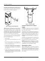
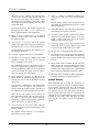
Temperature & Pressure Gauge
The temperature and pressure gauge is shipped loose
for field installation in the outlet piping.
20°F
∆
T 30°F
∆
T 40°F
∆
T
Min. Flow Max Flow
Model
No.
gpm
∆
P (ft)
gpm
∆
P (ft)
gpm
∆
P (ft)
gpm
∆
P (ft)
∆
T
gpm
∆
P (ft)
∆
T
503 44 2.8 29 1.4 N/A N/A 25 1.1 35 100 11.3 9
753 65 6.4 44 3.1 33 1.9 33 1.9 40 100 13.8 13
1003 87 12.0 58 6.0 43 3.7 43 3.7 40 113 18.6 15
1252 109 20.9 73 10.2 54 6.2 54 6.2 40 113 22.2 19
1503 N/A N/A 87 16.0 65 9.5 65 9.5 40 113 25.5 23
1753 N/A N/A 102 22.5 76 13.4 76 13.4 40 113 27.2 27
2003 N/A N/A 116 31.9 87 18.9 87 18.9 40 116 32.0 30
Notes: 1. Basis for minimum flow is ∆T . Basis for maximum flow is gpm.
Table F: Heater Rates of Flow and Pressure Drops

SECTION C: Installation
14
Hydronic Heating
Pump Selection
In order to ensure proper performance of your heater
system, you must install a correctly-sized pump. Ray-
pak recommends designing for a ∆T within the range
of 10°F to 40°F. See Table F for acceptable flow rates
for each model (∆T is the temperature difference be-
tween the inlet and outlet water when the heater is
firing at full rate).
Feedwater Regulator
Raypak recommends that a feedwater regulator be in-
stalled and set at 12 psi minimum pressure at the
highest point of the system. Install a check valve or
back flow device upstream of the regulator, with a
manual shut-off valve as required by local codes.
Piping
All high points should be vented. A heater installed
above radiation level must be provided with a low wa-
ter cut-off device (sales order option F-10). The heater,
when used in connection with a refrigeration system,
must be installed so that the chilled medium is piped in
parallel with the heater with appropriate valves to pre-
vent the chilled medium from entering the heater.
The piping system of a hot water heater connected to
heating coils located in air handling units where they
may be exposed to circulating refrigerated air, must be
equipped with flow control valves or other automatic
means to prevent gravity circulation of the heater water
during the cooling cycle. It is highly recommended that
the piping be insulated.
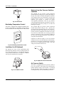
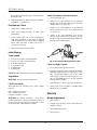
Air-Separation/Expansion Tank
All heaters should be equipped with a properly sized
expansion tank and air separator fitting as shown in
Fig. 9.
Fig. 9: Air-Separation/Expansion Tank
Three-Way Valves
Three-way valves intended to regulate system water
temperatures by reducing flow in the boiler should not
be used. Raypak heaters are high-recovery, low-mass
heaters which are not subject to thermal shock.
Fig. 10: Single Heater - Low-Temperature (Heat
Pump) Application with Primary/Secondary Piping
See Fig. 14 and instructions on page 16 for adjusting
the manual bypass.
Fig. 11: Dual Heaters (Reverse/Return)
with Primary/Secondary Piping
Domestic Hot Water
When designing the water piping system for domestic
hot water applications, water hardness should be con-
sidered. Table G indicates the suggested flow rates for
soft, medium and hard water. Water hardness is ex-
pressed in grains per gallon.

SECTION C: Installation
15
Fig. 12: Single Domestic Hot Water Heater and
Storage Tank
Potable Water and Space Heating
CAUTION: When this heater is used for both potable
water and space heating, observe the following to en-
sure proper operation.
1. All piping materials and components connected to
the water heater for the space heating application
shall be suitable for use with potable water.
2. Toxic chemicals, such as used for boiler treatment,
shall not be introduced into the potable water used
for space heating.
3. If the heater will be used to supply potable water,
it shall not be connected to any heating system or
components previously used with a non-potable
water heating appliance.
4. When the system requires water for space heating
at temperatures higher than 140°F, a means such
as a mixing valve shall be installed to temper the
water in order to reduce scald hazard potential.
Pool Heating
When a boiler or water heater is used in a pool heating
application, ensure that all the following installation
requirements are met.
CAUTION: Power to the heater should be interlocked
with the main system pump to ensure the heater does
not fire without the main system pump in operation.
Improper flow control can damage the heater. Uncon-
trolled flow (too high) or restricted flow (too low) can
seriously damage the heater. Follow these instructions
to make sure your heater is properly installed.
The MVB must be equipped with a field-supplied ex-
ternal pump and bypass arrangement. This arrangement
blends outlet water with the inlet water to increase the
inlet water temperature to a minimum of 120°F,
thereby reducing the likelihood of condensation form-
ing on the heat exchanger. The pump also serves to
circulate water through the heater from the main sys-
tem piping.
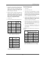
Soft (0-4 grains per gallon) Medium (5-15 grains per gallon) Hard* (16-20 grains per gallon)
Model
No.
∆
T
gpm
∆
P
MTS SHL
∆
T
gpm
∆
P
MTS SHL
∆
T
gpm
∆
P
MTS SHL
503 17 50 3.6 2 5.9 17 50 3.6 2 5.9 9 95 10.4 2 18.1
753 26 50 4.0 2 6.3 20 65 6.4 2 10.2 13 100 13.8 2 22.2
1003 30 58 6.0 2-1/2 7.2 20 87 12.0 2-1/2 14.4 15 113 18.7 2-1/2 22.6
1253 30 73 10.4 2-1/2 12.1 20 109 21.0 2-1/2 24.6 19 113 22.3 2-1/2 26.3
1503 30 87 16.0 2-1/2 18.5 23 113 25.7 2-1/2 29.6 23 113 25.7 2-1/2 29.6
1753 30 102 22.7 2-1/2 26.0 27 113 27.4 2-1/2 31.3 27 113 27.4 2-1/2 31.3
2003 30 116 32.0 2-1/2 36.1 30 116 32.0 2-1/2 36.1 30 116 32.0 2-1/2 36.1
∆T = Temperature rise, °F
∆P = Pressure drop through heat exchanger, ft
SHL = System head loss, ft (based on heater and tank placed no more than 5 ft apart and equivalent length of 25 ft of tubing)
gpm = Gallons per minute, flow rate
MTS = Minimum tubing size
* Must use optional cupro-nickel tubes. If over 20 grains per gallon, a water softening system must also be used.
Table G: Domestic Water Heater Flow Rate Requirements

SECTION C: Installation
16
To complete the installation of the pool heater, the pool
thermostat needs to be installed in the main return wa-
ter line, upstream of the heater. This will ensure that
the heater will be energized at the right time.
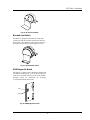
Fig. 13: Single Pool Heater Application
Adjustment of the manual bypass valve is critical to
proper operation of the heater. The manual bypass
valve should be adjusted to achieve a minimum inlet
water temperature of 120°F and a system supply water
temperature below 140°F. When starting with a cold
pool, make initial adjustments. Make final adjustments
when pool water approaches desired temperature.
The use of a bypass is required for proper operation in
a pool heating application. Use the following instruc-
tions to set the manual bypass:
1. Turn on pump.
2. Turn on heater and wait until heater goes to full
fire.
3. With the heater operating at 100% firing rate, set
Valve A (the bypass) to ½ open position, and
Valve B to fully open position.
4. Adjust Valve A until the inlet water temperature is
120°F. NOTE: Opening the valve will increase
the temperature and closing the valve will decrease
the temperature.
5. If this process does not raise the inlet water tem-
perature to 120°F and Valve A is fully open, then
slowly throttle Valve B closed to increase the inlet
water temperature to 120°F.
Fig. 14: “H” Bypass Setting
Automatic Chlorinators and Chemical
Feeders
CAUTION: Combustion air must not be contaminated
by corrosive chemical fumes which can damage the
heater and void the warranty.
All chemicals must be introduced and completely di-
luted into the pool or spa water before being circulated
through the heater. Do not place chlorine tablets or
bromine sticks in the skimmer. High chemical concen-
trations will result when the pump is not running (e.g.
overnight).
Chlorinators must feed downstream of the heater and
have an anti-siphoning device to prevent chemical
back-up into the heater when the pump is shut off.
NOTICE: High chemical concentrates from feeders
and chlorinators that are out of adjustment will cause
very rapid corrosion of the heat exchanger in the heater.
Such damage is not covered under the warranty.
Winterizing Your Heater
Heaters installed outdoors as pool heaters in freezing
climate areas should be shut down for the winter. To
shut down heater, turn off manual main gas valve and
main gas shut-off. Close isolation valves. Drain the
heater using the hose bibs located on the bottom of the
heat exchanger.

SECTION C: Installation
17
NOTE: There are 2 separate drains on the MVB that
must BOTH be drained to protect the heat exchanger.
These are both accessible by removing the lower front
door from the heater. Drain any piping of all water that
may experience below-freezing temperatures.
Pool/Spa Water Chemistry
NOTICE: Chemical imbalance can cause severe dam-
age to your heater and associated equipment.
Water Hardness
Water hardness is mainly due to the presence of cal-
cium and magnesium salts dissolved in the water. The
concentration of these salts is expressed in mg/l, ppm
or grains per gallon, as a measure of relative hardness
of water. Grains per gallon is the common reference
measurement used in the U.S. water heater industry.
Hardness expressed as mg/L or ppm may be divided by
17.1 to convert to grains per gallon. Water may be
classified as very soft, slightly hard, moderately hard or
hard based on its hardness number. The salts in water
will precipitate out when the water is heated and will
cause accelerated lime and scale accumulation on a
heat transfer surface.
Raypak water heaters can operate lime/scale-free using
potable water with a hardness not exceeding 20 grains
per gallon. Proper operation is achieved by setting the
temperature rise/water flow per the guidelines in the
installation instructions. If the hardness of the water
exceeds the maximum level of 20 grains per gallon
special measures must be taken to adjust flow and tem-
perature rise. Water should be softened to a hardness
level no lower than 5 grains per gallon. Water softened
as low as 0 to 1 grain per gallon may be under-
saturated with respect to calcium carbonate resulting in
water that is aggressive and corrosive.
pH of Water
pH is a measure of relative acidity, neutrality or alka-
linity. Dissolved minerals and gases affect water’s pH.
The pH scale ranges from 0 to 14. Water with a pH of
7.0 is considered neutral. Water with a pH lower than 7
is considered acidic. Water with a pH higher than 7 is
considered alkaline. A neutral pH (around 7) is desir-
able for most potable water applications. Corrosion
damage and water heater failures resulting from water
pH levels of lower than 6 or higher than 8 are non-
warrantable. The ideal pH range for water used in a
storage tank or a copper water heater system is 7.2 to
7.8.
Total Dissolved Solids
Total dissolved solids (TDS) is the measure of all min-
erals and solids that are dissolved in the water. The
concentration of total dissolved solids is usually ex-
pressed in parts per million (ppm) as measured in a
water sample. Water with a high TDS concentration
will greatly accelerate lime and scale formation in the
hot water system. Most high TDS concentrations will
precipitate out of the water when heated. This can gen-
erate a scale accumulation on the heat transfer surface
that will greatly reduce the service life of a water
heater. This scale accumulation can also impede ade-
quate flow of water and may totally block the water
passages in the tubes of the heat exchanger. A heat
exchanger that is damaged or blocked by lime/scale
accumulation must be replaced. Failure of a water
heater due to lime scale build up on the heating surface
is non-warrantable. The manufacturer of the water
heater has no control of the water quality, especially
the TDS levels in your system. Total dissolved solids
in excess of 2,500 ppm will accelerate lime and scale
formation in the heat exchanger. Heat exchanger fail-
ure due to total dissolved solids in excess of 2,500 ppm
is a non-warrantable condition. Raypak offers basic
temperature guidelines for operation of a potable water
heater on normal to moderate levels of hardness and
solids but levels of hardness and total dissolved solids
beyond normal limits for operation will require special
setup and operation.
NOTICE: Failure of a heat exchanger due to lime scale
build-up on the heating surface, low pH or other
chemical imbalance is non-warrantable.
Gas Supply
DANGER: Make sure the gas on which the heater will
operate is the same type as specified on the heater’s
rating plate.
Gas piping must have a sediment trap ahead of the
heater gas controls, and a manual shut-off valve lo-
cated outside the heater jacket. It is recommended that
a union be installed in the gas supply piping adjacent to
the heater for servicing. The gas supply pressure to the
heater must not exceed 10.5 in. WC for Natural Gas or
13.0 in. WC for Propane Gas. A pounds-to-inches
regulator must be installed to reduce the gas supply
pressure if it is higher than noted above. This regulator
should be placed a minimum distance of 10 times the
pipe diameter upstream of the heater gas controls.
Refer to Table H for maximum pipe lengths.

SECTION C: Installation
18
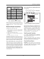
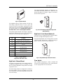
Gas Supply Connection
CAUTION: The heater must be disconnected from the
gas supply during any pressure testing of the gas
supply system at test pressures in excess of 1/2 psi
(3.45 kPa).
The heater must be isolated from the gas supply piping
system by closing the upstream manual shut-off valve
during any pressure testing of the gas supply piping
system at test pressures equal to or less than 1/2 psi
(3.45 kPa). Relieve test pressure in the gas supply line
prior to reconnecting the heater and its manual shut-off
valve to the gas supply line. FAILURE TO FOL-
LOW THIS PROCEDURE MAY DAMAGE THE
GAS VALVE. Over-pressurized gas valves are not
covered by warranty. The heater and its gas connec-
tions shall be leak-tested before placing the appliance
in operation. Use soapy water for leak test. DO NOT
use an open flame.
Fig. 15: Gas Supply Connection
CAUTION: Do not use Teflon tape on gas line pipe
thread. A pipe compound rated for use with natural and
propane gases is recommended. Apply sparingly only
on male pipe ends, leaving the two end threads bare.
CAUTION: Support gas supply piping with hangers,
not by the heater or its accessories. Make sure the gas
piping is protected from physical damage and freezing,
where required.
Gas Supply Pressure
A minimum of 4.0 in. WC and a maximum of 10.5 in.
WC upstream gas pressure is required under load and
no-load conditions for natural gas. A minimum of 4.0
in. WC and a maximum of 13.0 in. WC is required for
propane gas. The gas pressure regulator(s) supplied on
the heater is for low-pressure service. If upstream pres-
sure exceeds these values, an intermediate gas pressure
regulator, of the lockup type, must be installed.
When connecting additional gas utilization equipment
to the gas piping system, the existing piping must be
checked to determine if it has adequate capacity for the
combined load.
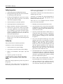
The gas valve pressure regulator on the heater is nomi-
nally preset as noted in Table I.
1” NPT 1-1/4” NPT 1-1/2” NPT 2” NPT 2-1/2” NPT
Model
No.
N P N P N P N P N P
503 15 35 65 150 130 360 N/A N/A N/A N/A
753 5 15 65 100 75 180 250 N/A N/A N/A
1003 N/A N/A 35 55 35 90 125 300 300 N/A
1253 N/A N/A 15 25 25 60 85 225 200 300
1503 N/A N/A 10 15 15 25 60 150 150 275
1753 N/A N/A N/A N/A N/A N/A 45 110 115 230
2003 N/A N/A N/A N/A N/A N/A 35 90 85 210
Natural Gas – 1,000 BTU/ft
3
, 0.60 specific gravity at 0.5 in. WC pressure drop
Propane Gas – 2,500 BTU/ft
3
, 1.53 specific gravity at 0.6 in. WC pressure drop
Table H: Maximum Equivalent Pipe Length
Page is loading ...
Page is loading ...
Page is loading ...
Page is loading ...
Page is loading ...
Page is loading ...
Page is loading ...
Page is loading ...
Page is loading ...
Page is loading ...
Page is loading ...
Page is loading ...
Page is loading ...
Page is loading ...
Page is loading ...
Page is loading ...
Page is loading ...
Page is loading ...
Page is loading ...
Page is loading ...
Page is loading ...
Page is loading ...
Page is loading ...
Page is loading ...
Page is loading ...
Page is loading ...
Page is loading ...
Page is loading ...
Page is loading ...
Page is loading ...
Page is loading ...
Page is loading ...
Page is loading ...
Page is loading ...
Page is loading ...
Page is loading ...
Page is loading ...
Page is loading ...
-
 1
1
-
 2
2
-
 3
3
-
 4
4
-
 5
5
-
 6
6
-
 7
7
-
 8
8
-
 9
9
-
 10
10
-
 11
11
-
 12
12
-
 13
13
-
 14
14
-
 15
15
-
 16
16
-
 17
17
-
 18
18
-
 19
19
-
 20
20
-
 21
21
-
 22
22
-
 23
23
-
 24
24
-
 25
25
-
 26
26
-
 27
27
-
 28
28
-
 29
29
-
 30
30
-
 31
31
-
 32
32
-
 33
33
-
 34
34
-
 35
35
-
 36
36
-
 37
37
-
 38
38
-
 39
39
-
 40
40
-
 41
41
-
 42
42
-
 43
43
-
 44
44
-
 45
45
-
 46
46
-
 47
47
-
 48
48
-
 49
49
-
 50
50
-
 51
51
-
 52
52
-
 53
53
-
 54
54
-
 55
55
-
 56
56
-
 57
57
-
 58
58


Raypak 503-2003 User manual
- Type
- User manual
- This manual is also suitable for
Ask a question and I''ll find the answer in the document
Finding information in a document is now easier with AI
Related papers
-
Raypak XTHERM 1005 User manual
-
-
-
-
-
-
Raypak 504A-2004A Types H, WH, and P User manual
-
-
-
Other documents
-
 ATrack AK11 Installation guide
-
Rheem Digital Low NOx Heaters Warranty
-
-
PVI Industries Btu/h GPH User manual
-
 Heat Transfer Phoenix PH-55 Installation & Operation Manual
-
Heat Transfer Products HPH130119 Installation guide
-
Phoenix PH199-55 Installation Operation & Maintenance
-
Vulcan-Hart Pool Heater Installation & Operating Manual
-
 Heat Transfer Phoenix Evolution PHE130-80 Installation & Operation Manual
-


