Epson MACLQ (Talk I/F for LQ Printers) User guide
- Category
- Print & Scan
- Type
- User guide
This manual is also suitable for

LQ-1070+
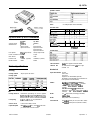
LQ-1070 and LQ-1070+ Differences
Acoustic Noise:
Scalable Fonts:
La-1
070
55dB(A)
2
Epson Roman
Epson Sans Serif
Print Speed
315cps (15cpi draft)
Printer Mechanism: M-5ElO
Main Board
Cl33
Product code:
CO63001 (LQ-1070)
Model Number:
P63OA
LQ-1070+
465dB(A)
4
Epson Roman
Epson Sans Serif
Epson Roman T
Epson Sans Serif H
337 cps (15cpi draft)
M-5JlO
C118
C118001 (LQ-1070+)
P63OB
Printer Specifications
Printing
Printing method:
Printing speed:
24-pin impact dot matrix
Off
on
1 15
1
337
1112
Invalid
I
1
1
I
cpt:
characters per inch
Printing direction:
Line spacing:
cps: characters per second
LQ: letter quality
Bidirectional logic-seeking for text and graphics.
UnidirectionaI for graphics (unidimctionaI
canbe
seIectedwithDIPswitchorsoftwarecommand).
l/6
inch,
l/8
inch, or programmable in
l/360-inch increments
Acoustic noise:
Less than 46.5 dB(A) normal
Paper feed speed:
65.2
miI.Iiseconds
per 1 /&inch line; 2.8 inches
per second with continuous feed
printable columns:
Buffer:
0 or 8 Kbytes (DIP-switch selectable)
Character fonts:
Font
Epson Draft
Epson Courier
&R-B
Epson
Scnpt
C
Epson Roman T
Epson Sans Serif
Ii
You can also select other font/pitch combinations
using
ESC/P
2 commands
Scalable fonts:
Character tables:
Character sets:
Mechanical
Paper-feed methods:
Ribbon:
MCBF:
MTBF:
Print head life:
1
italic
and 7 graphics character tables
14 international character sets and 1 legal
character set
Friction
Push-tractor
Pull-tractor
Single-bin cut-sheet feeder (optional)
Double-bin cut-sheet feeder (by combination of
both optional cut-sheet feeders)
Black
n&m
cartridge
#7754:
L.ife
expectancy
In
LQ
at 48
dots/character:
2
miIIion
characters
In draft, at 28 dok/characten 3.42
miIIion
characters
Film ribbon cartridge
#7770
(optional): Life
expectancy in
LQ
at 48 dok/characten 0.2 million
characters
For
aII
components (excluding print head):
3 miIIionIines
6000 power-on hours (25% duty)
200
miIIion
strokes per wire (with fabric ribbon)
100
miUion
strokes per wire (with film ribbon)
24-Pin Printers
7/20/93
LQ-1070+ - 1

LQ-1070+
Dimensions and weight:
Electrical
Height
16Omm
(6.3 inches)
Width 609 mm (24.0 inches)
Depth
368mm(14.5
inches)
weight
9.5
kg (21.0 lb)
Rated voltage:
AC 120 V (120 V model)
Input voltage range: AC 103.5 to 132 V (120 V model)
Rated current:
2.0
A (120 V model)
Power consumption:
(during self-test printing in draft mode,
at 10 cpi) Approx. 36 W (120 V model)
Rated frequency range: 50 to 60 Hz
Inputfrequency range: 49.5 to 60.5 Hz
Insulation resistance: 10
MR
minimum (at DC 500 V between AC
power line and chassis)
Dielectric strength (between AC line and chassis):
120
V model:
AC 1.0 kV (rms), 1 minute
or AC 1.2
kV
(rms), 1 second
Environmental
Temperature: Operation:
5”
to 35°C
(41”
to 95°F)
Storage: -30” to 60°C (-22” to 140°F)
Humidity:
Operation: 10% to 80% RH without
condensation
Storage: 5% to 85% RH without condensation
Paper
Single sheets:
Width
top
148 to 420 mm (5.8 to 16.5 inches)
front 182 to 364 mm (7.2 to 14.3 inches)
IJ=gth
364 mm (14.3
inches) maximum
Thickness 0.065 to 0.14 mm (0.0025 to 0.0055 inches)
weight
52.3
to 90
g/m2
(14 to 24 lb)
Single-sheet multi-part
fms:
Width 182 to 364 mm (7.2 to 14.3 inches)
LeIYi+
257
mm to 297 mm (10.1 to 11.7 inches)
copies Four sheets (1 original plus up to 3 copies)
ThiCklESS
0.12
to 0.32 mm (0.0047 to 0.012 inches)
Weight
40
to 58
g/m2
(12 to 15 lb) per sheet
l Load single-sheet multi-part forms only
into the front slot.
l Use only carbonless multi-part forms.
Continuous paper:
Width 101 to 407 mm (4 to 16 inches) for
LQ-1070+
copies
Four sheets (1 original plus up to 3 copies)
ThickneSS
0.065 to 0.10 mm (0.0025 to 0.0039 inches) for
one sheet
Weight
0.065 to 0.32 mm (0.0025 to 0.012 inches) total
52.3
to 82
g/m2
(14 to 22 lb) for one sheet
40 to 58
g/m2
(12 to 15 lb) per sheet in multi-
part forms
l Use only carbonless multi-part forms.
Labels (continuous only):
Size
63.5
x23.8mm(2?4~15/16
inches)
101 x 23.8 mm (4 x
15/16
inches)
101 x 27 mm (4 x
17/16
inches)
Thickness
0.07
to 0.09 mm (0.0028 to 0.0031 inches) for
backing sheet
Envelopes:
Size
ThiCkIE?SS
weight
0.16
to 0.19 mm (0.0063 to 0.0075 inches) total
l
Use continuous type labels only.
l
Use labels only under normal temperature
and humidity conditions.
No. 6-166 x 92 mm (6.5 x 3.6 inches)
No. 10-240 x 104 mm (9.5 x 4.1 inches)
0.16
to 0.52 mm (0.0063 to 0.0197 inches)
45
to 91
g/m2
(12 to 15 lb)
l
Use envelopes only under normal
temperature and humidity conditions.
l
Insert envelopes into the top slot only.
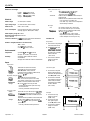
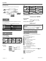
Printable area:
Single sheets
A Theminimum top margin
is 8.5 mm (0.33 inches).
B The
rninhum
left and
rightmarginsare3mm
(0.12
inches). However,
the maximum printable
width is 345 mm
(13.6 inches).
C Theminimum bottom
margin is 13.5 mm
(0.53 inches).
Continuous paper
A The
minimum top and
bottom margins (above
and below the perforation)
are
9 mm (0.35
inches).
B Theminimum left and
right margins are 13 mm
(0.51 inches). However,
the maximum printable
width is 345 mm
(13.6 inches).
Envelopes
A Theminimum top
margin is 8.5 mm
(0.33 inches).
B Theminimum left
and right margins
are
3 mm (0.12
inches).
C Theminimum bottom
margin is 13.5 mm
(0.53 inches).
Printable area
‘II
I
I
Printablearea
J-6
24-Pin Printers
LQ-1070+ - 2
7/20/93

LQ-1070+
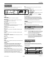
The Control Panel
ALT
The indicator lights give you the current status of the printer. The
buttons let you control many of the printer settings.
While holding down this button, pressing certain other buttons
results in the following:
BUFFER CLEAR
(PAUSE)
clears the printer’s buffer and initializes
?
(LOAD/EJECT)
feeds paper forward in l/MO-inch
,
’ 1
(LF/FF)
feed paper backward in
l/180-inch
Lights
OPERATE (green)
On when operate switch is on and power is supplied.
PAUSE (yellow)
On when the printer is not ready to print data. Stays off unless you
press the
PAUSE
button to prevent printing.
DATA (yellow)
On when data is present in the printer’s buffer.
MULTI-PART(green)
On when you move the paper-thickness lever to position 2 or higher.
The printing speed is reduced when this light is on.
PAPER OUT
(red)
On when the printer runs out of paper.
BIN 1
(green)
On when bin 1 of the optional cut-sheet feeder is selected for paper
feeding.
BIN 2 (green)
On when bin 2 of the optional cut-sheet feeder is selected for paper
feeding.
TEAR OFF (yellow)
On when you press the
TEAR OFF
button to feed the paper to the tear-
off position
Fonts
(green)
On when a specific font is selected.
Buttons
PAUSE
Press this button to temporarily stop printing. Press this button again
to resume printing.
LOAD/EJECT
Press this button to load single-sheet or continuous paper to the
loading position (however, the printer normally loads paper
automatically). If single-sheet paper is already in the loading
position, use this button to eject the sheet. If continuous paper is in
the loading or tear-off position, press this button to feed it backward
to the standby position.
LF/FF
(Line feed/Form feed)
Tap this button briefly to feed the paper forward one line. Hold this
button down to eject a single sheet of paper or advance continuous
paper to the top of the next page. You can also use this button to load
a single sheet of paper from the cut-sheet feeder or to feed
continuous paper from the standby position to the loading position.
increments
Bin Select/TEAR OFF
This button selects the paper bin when both optional cut-sheet
feeders are installed and you are printing on single sheets. When
printing on continuous paper, press this button once to feed paper
from the loading position to the tear-off position Press this button
again to feed the paper backward to the loading position
CONDENSED
Press this button to print condensed characters. Press again to return
to normal character printing.
FONT
Press this button to select from among the built-in fonts.
Note: The panel’s font name typestyles are meant as guides only;
actual printed
resdk
may differ slightly.
Other control-panel features
The control panel also gives you access to two special functions:
self test:
Hold down the
ALT
button while turning on the printer
to perform the self test. The self test lets you check that
your printer is operating properly and gives you a
printout of the current DIP-switch settings.
Data dump:
Hold down both the
LF/FF
button and
LOAD/EJECT
button while turning on the printer to enter data dump
mode. Data dump mode allows advanced users to find
the cause of communication problems between the
printer and the computer.
Setting the DIP Switches
DIP-switch tables
The section below shows the settings and functions of each DIP
switch. You can see the current DIP-switch settings at any time by
running the self test.
Table 2 DIP switch 2
SW
I-1
l-2
1-3
1-4
I-5
I-8
1-7
l-8
D4BSCflptlOtl
International character sets/
character tables
Print direction
Not used
Input buffer
1 -inch skip-over-perforation
ON
1
OFF
Sea Tables 3 and 4 below
Unidirectional
Bidirectional
-
-
None
8
Kbytes
On
Off
24-Pin Printers
7/20/93
LQ-1070+ - 3

LQ-1070+
Table 2 DIP switch 2 International character sets
SW Deecrlptlon
2-1
Page length (for continuous
2-2
paper)
ON
1
OFF
See Table 5 below
2-3
Tear off
2-4 Auto line feed
On
Off
On
Off
Table 3 International character sets
Sweden
w
Spain 1
off
On
off
Off
Off
off
On
Off
Off Off
off
Off
Table 4 Character tables
Character table
Italic
PC 437
(Unrted
States)
PC 850 (Multilingual)
PC 860 (Portugal)
PC 863 (Canada-French)
PC 865 (Norway)
l-l
1
l-2 1
l-3
Set international character sets
according to Table 3 above
On On On
On On
Off
14
Off
On
On
On
Off
On
On
On
Off
Off
On
Off
On On
On
Table 5 Page length
Page
length
6.5 inches (216 mm)
1
2-l
1
2-2
I Off
I On
.
I
11 inches (279 mm)
11.7 inches
(296
mm)
12 inches 1305 mm)
Off Off
On On
On
Off
DIP-switch functions
This section
descriies
all of the functions you can select with the DIP
switches.
International character sets
You can change 12 characters in the italic character table to suit your
printing needs. Since these characters are often used in other
languages, they are named after countries and referred to as
international character sets.
Select the international character set with DIP switches
l-2,1-3,
and
l-4, according to DIP-switch Table 3.
The character sets you can select by DIP switch are USA, France,
Germany, United Kingdom, Denmark I, Sweden, Italy, and Spain I.
However, you can also select the following sets with the ESC R
software co
mmand: Japan (English), Norway, Denmark II, Spain II,
Latin America, Korea, and Legal.
Country
0 USA
1
France
2
Germany
3
United
Kingdun
4
Dermark
I
5 Sweden
6
W
7 Sparn
I
ASCII code (hex)
1
DIP switch
1
23
24
40
56
5C
SD SE
60
78
7C
70
7E
l-l
1-2
l-3
t-4
X
$
e
I
\
I
*
’
1
I
1
W
OnOnOnCff
#
S
B
l
q
8
A
t
6
Bb
..
OnOnOff
off
t$B#au-
t
&
8
(i
B
OnOffOn
off
e
t
e ( \
1
A
t
{
;
)
-
OnOffOff
Off
#$edOA^t~eA’OffOnOn
off
tnBXe,AU6iiijAilOffOn~
off
d$e*\6
A
h
A
b
&
3
0ffOffOn
Off
R $ e
i
R
i
A
t
,.
A)
*
OffOffOffOff
The following eight additional sets are available only by using the
ESC R software command.
Additional international character sets
Country
ASCII
code
(hex)
23 24
40
56
5C 5D
SE
60
76
7C
70
7E
8
Japan
(EwW
# $
e
[
Y
]
-
’
{
:
)
-
Q Norway
Yn12RBAUCaabii
10 Denmark II
WtPa0AUieeAii
11
Sparn
II
#$rijfi~l5’
i
A 6 ii
12 Latin America
#SBjRi Ciiifidti
13 Korea
xre[w]-‘(;}’
64 Legal
#$fi”“y’aot-
Character tables
Your printer has six character tables built-in five graphics character
tables and one italics character table.
You can select the character tables with DIP switches
l-2,1-3,
and
1-4, according to Table 4.
To select a graphics character table, you must first turn DIP switch
l-4
on.
Note: If you send the ESC t 1 comman
d (to select graphics) while
DIP switch
1-Q
is off, the graphics character table is always PC 437
(United States).
Print direction
Printing is normally bidirectional. However, turning DIP switch 1-5
on for unidirectional printing-in which the print head
prints
in one
direction only-allows for precise vertical printing alignment. This
makes it ideal for printing graphics such as lines or boxes.
If DIP switch l-5 is on, printing is unidirectional even if you select
bidirectional with the ESC U 0 software command.
Note: If you send the ESC t 0 command (to select italics) while DIP
switch
l-4
is on, the international character set is always USA.
Lq-1070+ - 4
7/20/93
24-Pin Printers

LQ-1070+
Input buffer capacity
The printer stores print data sent from your computer in its input
buffer. Keep DIP switch l-7 off to select an
8Kbyte
buffer.
Skip-over-perforation
Turning DIP switch l-8 on when you are using continuous paper
enables the skip-over-perforation function Use this function to leave
a l-inch (25.~mm) margin between the last printable line on one
page and the first printable line on the next page. This causes the
printer to skip over the perforation between continuous sheets.
Most application programs take care of the top and bottom margins.
Do not turn on skip-over-perforation unless your program does not
provide these margins.
Adjust your top-of-form position with the MICRO
FEED buttons
to get
half of the margin at the bottom of one page and half at the top of the
next page.
Continuous paper page length
When you are printing on continuous paper, DIP switches 2-1 and
2-2 let you select from the four page lengths described in DIP-switch
Table 5.
Tear off
When you turn DIP switch 2-3 on, the tear-off feature is automatic
when using continuous paper. The printer automatically advances
the last printed page to the tear-off position You can then easily tear
off the printed paper.
The printer automatically returns the paper to the loading position
when it receives more print data. You can also return the paper to the
loading position by pressing the TEAR
OFF
button or the
LOAD/EJECT
button.
Use the tear-off feature only with continuous paper loaded with the
push tractor. Do not use the tear-off feature with the pull tractor.
Auto line feed
When auto line feed is on (DIP switch 2-4 on), the printer
accompanies each carriage-return code (CR) received with a linefeed
code (LF).
If your printer is double spacing, turn DIP switch 2-4 off. If each line
overprints the next, turn DIP switch
24
on
Interface Specifications
Your printer is equipped with a parallel interface.
Specifications and pin assignments
The built-in parallel interface has the following characteristics:
Datafbrmat:
8bit
parallel
Synchronization:
STROBE pulse
Handshake
timing:
BUSY and
m
signal
Signal
led:
TTL compatible level
Gwmec tar:
36pi.n 57-30360 (Amphenol) connector
or equivalent
Connector pin assignments and a description of their respective
interface signals are shown in the following table.
:
2
DATA DATA 2 1
4
E
DATA 3
5
DATA 4
6 24
DATA 5
7
25
DATA 6
:
;;
DATA DATA 8 7
10
28
ACKNLG
11
29
BUSY
12
30 PE
I
I
13
-
SLCT
”
31
16
INIT
32
-
ERROR
Dlrectkn
IN
OUT
OUT
OUT
IN
-
-
-
-
-
IN
OUT
-
-
OUT
IN
Descrldlon
.
STROBE pulse to read data.
Pulse-
width must be more than 0.5
microseconds at the
recervrng
terminal.
These signals represent
informatron
of the 1 st to 8th bits of parallel data,
respectively. Each signal is at HIGH
level when data is logical 1 and
LOW when it is logical 0.
About an 11 -microsecond pulse.
LOW indicates that data has been
received and that the printer is
readv to
acted
more data.
HIGH signal indicates that the
printer cannot receive data. The
signal goes HIGH in the
followrng
cases:
1) During data entry (ea. char. time)
2) During printing
3) During PAUSE
4) During printer-error state
-
A HIGH
sianal
indicates that the
printer is
&t
of paper.
-
Pulled up to
5V
through 3.3 Kohm
resistance.
When this signal is LOW, the paper
is automatically fed 1 line after
printing. (The signal level can be
fixed to this by
settrng
DIP
switch
2-4 to ON.)
Not used.
Logic ground level.
Printer’s chassis ground, which is
-
isolated from the logic ground.
-
Not used.
Twisted-pair return signal ground
-
level.
When this level becomes LOW, the
printer controller is reset to its
crower-uo
state
and the
onnt
buffer
is
cleared. This level is
normally
HIGH; its pulse width must be more
than 50 microseconds at the
receiving terminal.
This level becomes LOW when the-
printer is: 1) in paper out state, 2) in
PAUSE state, 3) in error state
Same as for Pins
19-30.
Not used.
Pulled up to 5V through 3.3 Kohm
The DCl/DC3 code is
valid
only
when this signal is HIGH. This
signal is always LOW.
Note:
l The column heading “Direction” refers to the direction of signal
flow as viewed from the printer.
.
“Return” denotes the twisted-pair return to be connected at
signal ground level. For the interface wiring be sure to use a
twisted-pair cable for each signal and to complete the
connection on the return side.
l All interface conditions are based on
TTL
level. Both the rise
and fall times of each signal must be less than 0.2 microseconds.
l Data transfer must be carried out by observing the
ACKNLG
or
BUSY signal. (Data transfer to this
printer can
be
carried out
only after receipt of the ACKNLG signal or when the level of
the BUSY signal is LOW.)
24-Pin Printers

LQ-1070+
Paper:
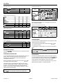
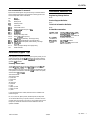
Interface timing
The figure below shows the timing for the parallel interface:
-==#=zk
ACKNLG
Interface Cards
You can use optional interface boards to supplement your printer’s
built-in parallel interface.
The Epson interfaces below are compatible with your printer:
Model Number
Name
C823051
Serial interface card
C823071
32
KB
serial interface card
C823101
MACLQ
32
KB
parallel interface card
Eoson Talk interface card
Option Specifications
Cut-sheet feeders
Dimensions and weight
Printer
Cut+hest feeder
Height
Width Depth
Weight
LQ-
1070+
Single-bin
377
mm 60Qmm
444mm
0.75
kg
C806391
(14.8 inches) (24.0 inches)
(17.5 inches) (1.65 lb)
L&1070+
Hlgh-capactty
367
mm 60Qmm
434mm
2.15kg
C806401
(14.4 inches)
(24.0 inches)
(17.1 inches) (4.74 lb)
Note: Dimensions when mounted on the printer; includes printer
dimensions
Bin capacity
Single sheets: c806391
Up to 50 sheets of
82-g/m*
(22-lb) paper
C806401
Envelopes:
Up to 150 sheets of
82-g/m*
(22-lb) paper
C806401
Up to 25 (plain bond)
Up to 30 (air
mail)
single
sheets
Envelopes
Width C806391 182 to 420 mm
N/A
(7.17 to 16.5 inches)
C806401 182 to 420 mm 165 to 241 mm
(7.1710 16.5 inches)
(6.50
to 9.49 inches)
Length 210 to 305 mm
92tolO4mm
(8.27 to 12.00 inches)
(3.62
to 4.09 inches)
Thickness 0.07 to 0.10 mm
0.16to0.52mm
(0.0028
to 0.0039 inches)
(0.0063 to 0.0205 inches)
Weight
64t082dm2
45
to 91
g/m2
1
(I 7 to
22-lbs)
I(12
to
24-lbs)
I
Paper storage conditions:
Temperature: 18” to 22°C (64’ to
72OF)
Humidity: 40% to 60%
Environmental
Temperature:
Operation: 5” to 35°C (41” to 95°F)
Storage:
30”
to 60°C (-22” to 140°F)
Humidity (without condensation):
Operation: 15% to 80%
Storage: 5% to 90%
Note:
l 9&g/m* paper printing is only available at normal operating
conditions.
l Envelope printing is only available with the
C806381
cut-sheet
feeder, at normal operating conditions.
Command Changes from ESC/P
New Commands
The following are new comman
ds that have been added to the
ESC/P command set:
EsC(C
ESC(G
=tu
=tv
Et”
=3C
=(t
=(v
Est.
ESC X
ESC C
Set page length in defined unit
Select graphics mode
Define unit
Set absolute vertical print position
Print data as characters
Set page format
Assign character table
Set relative vertical print position
Print raster graphics
Select font by pitch and point
Set horizontal motion index (HMI)
Deleted Commands
The following commands are not supported on Epson ESC/P 2
printers:
ESCb
Set vertical tabs in VFU channels
Esc/
Select vertical tab channel
ESCa
Select justification
LQ-1070+ - 6
7/20/93
24-Pin Printers

LQ-1070+
Non-recommended Commands
Information Reference List
Epson recommends against using the following commands because
some of these commands are not supported in existing printers and
some are duplicates of other commands.
Engineering Change Notices
BEL
B=per
Bs
Backspace
DC1
Select printer
CAN
ESC#
Esc<
Esc=
Esc>
ESC?
ESCA
ESCK
ESCL
ESCY
Deselect printer
Cancel data
Cancel MSB control
UnidirectionaI
printing for one
Iine
SetMSBtoO
SetMSBtol
Reassign bit-image mode
Select
n/&%inch
line spacing
Select
8-dot,
single-density, bit-image printing
Select
8dot,
double-density, bit-image printing
Select
8dot,
double-speed, double-density, bit-image
printins
Escz
DEL
Select quadruple-density bit-image printing
Delete character
None.
Product Support Bulletins
None.
Technical Information Bulletins
None.
Related Documentation
LQ107O+ADD LQ-570/1070
and LQ570+/1070+,
ActionPrinter
5000/5500
and
ActionPrinter
5000+
Service Manual
PL-LQ1070+
SI’KLQ1070+
4002064
LQ-1070-k Parts Price List
LQ-1070+
SeIf
Paced Kit
LQ-57O+/LQ-107%
User’s Guide
Installation/Support Tips
Most application programs let you specify the type of printer you use
so that the program can take full advantage of the printer’s features.
Many of these programs provide an installation or setup section that
presents a list of printers.
Choosing from a menu
To take
full
advantage of your printer’s features, including ESC/P 2,
choose the LQ570+/1070+ or Stylus
800/1000
from the menu. If
these printers are not listed, contact the software manufacturer to see
if an update to the software is available.
Until
you receive an update,
choose from the following
list:
ActionPrinter 5000+
ActionPrinter 5000
LQ-570/1070
LQ-870/1170
LQ-100
SQ-870/1170
LQ-510/550
LQ-500
LQ-86O/LQ-1060
LQ-85O/LQ-1050
LQ-2550
If none of these printers is listed, select the first one available from
the following list:
EX, FX, LX, RX, MS, Epson printer, Standard printer, Draft printer
To use all the features of your printer, however, it is best to choose a
program with your printer on its menu. If your program does not list
this printer, contact the manufacturer of the software to see if an
update is available.
24-Pin Printers
7/20/93
LQ-1070+ - 7
-
 1
1
-
 2
2
-
 3
3
-
 4
4
-
 5
5
-
 6
6
-
 7
7


Epson MACLQ (Talk I/F for LQ Printers) User guide
- Category
- Print & Scan
- Type
- User guide
- This manual is also suitable for
Ask a question and I''ll find the answer in the document
Finding information in a document is now easier with AI
