Page is loading ...

(Page&1)&
&
B. David Company RS-90 RC-93 RP-100
Nano Filtration System
Instructions and Operating Manual
Model # 9333
Important – set flow meter to 1000 gallons -Filter placement above-
(B. David Specific filters)
Specifications
Pressure Range:
Temperature Range:
Service Flow Rate
@60 psi (4.1 bar):
Rated Service Life:
&
&
&
2.1--8.62 bar (20-115 psi)
4.4-38.8°C (4G-102°F)
&
2.3
Lpm at 4.1 bar 0.6 gpm
3,785 L (1000 gallons)
&
•
After prolonged periods of non-use (such as during a vacation)
it
is
recommended that the system be flushed thoroughly. Let
water
run for 5-6 minutes before using.
•
The filter cartridges used with this system have a limited service
life. Changes in taste, odor, and/or flow of the water being filtered
indicate that the cartridges should be replaced.
Dimensions: 394 mm x 133 mm x 356 mm
(15.5 in. x 5.25 in. x 14 in.)
Weight (filled with water): 8.6 kg (19 lbs.)
&
Parts Included
•Filter system with filter cartridges
•Installation hardware (mounting screws, saddle valve, fittings)
• 6.35 mm (1/4-inch) tubing
•
Lead-free faucet
I Installation
•
For standard under-sink installation on 10 mm (3/8-inchl cold
water line.
•
Please read all instructions and precautions before installing and
using your filtration System.
•
Numbered diagrams correspond with numbered steps.
&
1.
Installing the Saddle Valve
Diagram on page 2
Use of a hand drill is recommended. To protect
Tools and Materials
Required:
•
Safety Glasses
•Hand or electric drill
(cordless recommended)
•File
•
Phillips head screwdriver
•2 Adjustable wrenches
•Tube cutters or utility knife
&
&
Precautions
Iiiif sink does not have hole
for separate faucet:
•
Center punch
•
19 mm (3/4-inch) drill bit
yourself from serious injury or fatal shock when using an electric
drill,
be sure the drill and the outlet
it
is plugged into are properly
grounded. When using a drill, follow the manufacturer's guidelines
and procedures.
NOTE: Saddle valve must be installed on a 51 mm (2-inch) long,
straight-
walled section of 10-22 mm (3/8-inch to 7/8-inch) steel, brass,
copper, or
PVC pipe.
(A) Turn off cold water supply and (turn on nearest faucet before
starting installation. Place a tray or towels under the cold water
line to catch excess water.
(C) Drill a 3 mm (1/8-inch) hole in cold water line. Remove any
burrs
with sandpaper or file.
(D)
Turn handle on the saddle valve to expose lance no more than 5
WAR NING
&
L
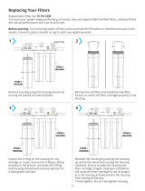
Protect filters against freezing, which can
cause
cracking of the filter and water leakage.
The rubber o-ring provides the water-tight seal between
the cap and the bottom of the housing.
It
is important that
the o-ring
be properly seated in the groove below the threads of the
housing or a
water leak could occur.
To prevent costly repairs or possible water damage, the
sump of plastic housings must be replaced every five years
for clear,
and ten years for opaque.
If
sump is older than
recommended, replace
immediately. Date sump for
reference and indicate replacement date.
NOTE:
•
For cold water use only.
•
Make certain that installation complies with all local
laws and regulations.
mm (3/16-inch) beyond black rubber gasket.
(E)
Place valve body over hole in cold water line so lance fits into
hole.
(F)
Attach back plate of clamp and tighten bolts evenly and firmly so
brackets are parallel.
(G)
Turn valve handle clockwise to closed position and leave closed
until installation is complete.
2. Selecting the Faucet Location
Diagram on page 2
NOTE: The drinking water faucet should be positioned with function,
convenience, and appearance in mind. An adequate flat area is
required to allow faucet base to rest securely. The faucet fits
through
a 19mm (3/4-inch) hole. Most sinks have pre-drilled 35 or
38mm
(1-inch) diameter holes that may be used for faucet
installation of
these pre-drilled holes cannot be used or are in an
inconvenient
location,
it
will be necessary to drill a 19mm (3/4-inch)
hole in the
sink to accommodate the faucet.
&

'
DO NOT ATIEMPT TO DRILL THROUGH AN ALL-PORCELAIN SINK. If you have an all-
porcelain sink, mount the faucet in pre-drilled sprayer hole or drill through countertop next to
sink..
When drilling through a countertop make sure the area below the drilled area is free of wiring
and piping.
Make certain there is ample room to make the proper connections to the bottom of the faucet.
Do not
drill through a countertop that is more than 25mm (1-inch) thick.
Do not attempt to drill through a tiled, marble, granite or similar countertop. Consult a plumber
or
the countertop manufacturer for advice or assistance.
(A)
Line bottom of sink with newspaper to prevent metal shavings, parts, or tools from falling down drain.
(B)
Place masking tape over the area to be drilled to prevent scratches if drill bit slips.
(C)
Mark hole with center punch. Use a 6mm (l/4-inch) drill bit for a pilot hole, then, using a 13mm
(3/4-
inch) drill bit or hole saw, drill a hole completely through the sink. Smooth rough edges with a
file.
&
3.
Mounting the Faucet
(A)
Remove wing nut (C) and metal washer (B) from the threaded shaft of the faucet. Leave
the black
rubber washer (A) on the threaded shaft.
(B)
Slide the threaded shaft of the faucet into drilled hole.
(C)
From under the sink, slide the metal washer on and thread on the wing nut. Tighten wing nut by hand
until tight.
I t
may be necessary to have a second person hold the faucet while tightening the wing
nut.
NOTE: Do not over tighten the wing nut. Hand tighten only. Do not use pli iers or wrench to tighten.
4.
Mounting the System
(A)
Center system between water supply adapter and drinking water faucet.
NOTE: Allow 38 mm (1.5 inches) clearance below system to enable filter cartridge changes.
(B)
Install mounting screws at least 380 mm (15-inches) from cabinet floor and 235 mm (9 1/4 inches)
apart.
Leave enough space [approximately 13 mm (l/2-inch)] between the head of the screw and the
wall to
slip system onto screws.
(C)
Place system over screws on wall and slide sideways. Tighten screws.
Caution: Make certain system is firmly attached to wall to prevent
it
from falling and possibly being
damaged.
&
5.
Connecting the Faucet (diagrams on page 3)
Caution:
Do not over-tighten compression nut. Use caution not to bend or crimp tubes when securing.
(A) Locate compression nuts in installation kit and faucet package.
(8) Attach compression nuts to faucet stem and Effective Life Indicator (ELI) and hand tighten. Then
loosen compression nut one full turn.
NOTE: If the compression nut should come apart, reference diagram 5A for correct reassembly.
6.
Attaching Tube
(A)
Attach tube to compression nut on faucet stem by inserting tube into the compress on nut opening.
Gently push the tubing until it comes to a stop.
Caution: Tube must be fully inserted in the compress on fitting base to the tube stop on the faucet stem
and on the outlet stem of the ELI.
(B)
Turn the nut hand tight.
(C)
Wrench tighten the nut 1 ½ to 2 turns.
NOTE: All nuts must be retightened when the system reaches projected operating temperature.
NOTE: A squeaking sound when tightening the nut
is
normal.
If
fittings are removed, Teflon® tape
must be used for pipe threaded connections.
NOTE: Compression nut should come preassembled with ferrules inside.’ F’ nut should come apart, see
figure 5A for proper reassembly.
(D)
Determine the length of tubing needed from the faucet to the ELI and cut the tubing. A slight sag in
the lines will allow for some ease in installation. Insert the tubing into the compression nut on the ELI.
Repeat steps 68 and 6C.
7.
Connecting the Saddle Valve
A) Determine the length of plastic tubing needed to connect the inlet (left) side of the filter with the
saddle valve. Be sure to allow enough tubing to prevent kinking and cut the tubing squarely. Slide
brass compression nut onto tubing, followed by plastic ferrule. The long, tapered end of the ferrule
should face towards the end of the tubing. Place insert into end of tubing.
(B) Insert tubing into saddle valve and hand-tighten compression nut. Using a wrench tighten nut 1 to 1 ½
turns.
&
&
&
&
&
&
&
&
&
&
&
&
&
&
&
&
&
&
&
&
&
&
&
&
&
&
&
&
&
&
&
&
&
&
&
3&
&
&
&
&&&&&&
&&Rubber&&&&&&&&
Washer&
&
&
&
&
&&&&&&&&Wing&nut&&
&
&&&&&&&&&&&&&&&&&&&&&&&
&&&&&&&&&&&&&&&&&&&&&&&&&&&
(Page&2)&
&
&
'
'
•
•
•
•
'
'
&
Me
tal&
I

..
.....
8.
Connecting Inlet Line to System
A) Locate Compression Nut in installation kit package and attach to inlet fitting. Tighten the nut is
hand tight and then loosen one full turn.
(B) Repeat steps 6B and 6C.
&
9.
Setting the Effective Life Indicator
The effective life indicator is the black dial located on the center of the mounting bracket. Each white
mark on the dial represents 378.5L (100 gallons). The START mark represents 4542.5L (1,200 gallons);
however, the filter cartridges have an effective life of 3785.4L (1,000 gallons), so you will need to move the
dial clockwise so that the indicator arrow lines up with the 3785.4L (1,000 gallons) mark (2 marks past
The START mark). Important – set flow meter to 1000 gallons after each new filter replacement.
NOTE: To prevent indicator malfunctions, only move the dial when the system is depressurized.
10.
Putting the System into Operation
(A) Slowly turn on cold water supply.
(B} Press red pressure relief button on top of system.
(C)
Make sure effective
life
indicator
is
set at 3785.4L (1,000 gallons)
.
(D)
Rotate base of drinking water faucet counter-clockwise to "ON" position. Allow water to run for 5
minutes to flush air and carbon fines from filter cartridges. Check system for leaks before leaving
installation.
NOTE: A drinking water cartridge may contain carbon fines (very fine black powder). After installation,
flush the cartridge for 5 minutes to remove the fines before using the water.
It
is recommended
that you run the tap at least 20 seconds prior to using water for drinking or cooking purposes.
NOTE: Initially, filtered water may appear cloudy. If you set a glass of water on a level surface, you should
be able to watch the cloudiness disappear from the bottom of the glass upwards. This harmless
cloudiness results from the release of trapped air within the cartridge and will disappear within a
few weeks after installation.
INSTALLATION IS NOW COMPLETE.
&
&
Filter Cartridge Replacement
Filter cartridges will last about 3785 liters (1,000 gallons) or twelve months before they need to
be
replaced. Filter cartridge life varies depending on filter life, usage, and/or water conditions.
Changes
in taste, color, and flow of the water being filtered indicate that the cartridge should be
replaced.
Read all instructions before replacing filter cartridges.
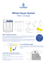
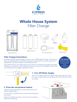
1.
Turn off cold water supply to system and press red pressure-relief button.
2.
Unscrew and remove bottom of filter housing. Locate and remove large o-ring, wipe clean of
lubricant, and set aside. Repeat for second and third housings.
3.
Discard used filter cartridges. Using a non-abrasive sponge or cloth, scrub the bottom of filter
housings, o-ring grooves, and caps with dish soap and warm water. Rinse thoroughly .Fill
bottom
of each housing 1/3 full with water. Add 14.7ML (1 tablespoon) of household bleach and
scrub to disinfect.
Caution: Read "WARNING" information on the bleach container before using its contents.
4.
Lubricate o-rings with clean silicone grease. Insert each o-ring in groove and press into place.
NOTE: This step is important to ensure a proper housing seal. Make certain each o-ring
is
seated
level
in
its groove or a leak may occur.
5.
Screw bottom of housings with bleach water onto caps without filter cartridges and hand-tighten. Do
NOT OVER-TIGHTEN.
6.
Turn on water supply. Let faucet run for about 10 seconds, then turn off faucet and let stand for 20-
30
minutes.
7.
Turn on faucet and allow bleach water to run out (about 3-5 minutes).
8.
Turn off water supply to system and press pressure-relief button. Remove bottom of housings and
empty out water.
9.
Insert each filter cartridge in bottom of appropriate filter housing.
10.
Screw bottom of housings onto caps and hand-tighten.DO NOT OVER-TIGHTEN. Make certain cap
standpipe slips into cartridge.
11.
Reset effective life indicator to 1000 gallons (see instructions under "Setting the Effective Life
Indicator" on Page 3).
12.
Turn on water to system and press pressure-relief button. Let faucet run for 5 minutes to
remove
trapped air and carbon fines. Check system for leaks before leaving installation.
&
&
Page 3
&
&
&
&
&
&
&
&
&
&
&
&
&
&
&
&
&
&
,
......---I-T......
..
'
A :
'
:
........_
,

NOTE: A drinking water cartridge may contain carbon fines
(very fine black powder). After installation, flush the cartridge
for 5 minutes to remove the fines before using the water. It is
recommended that you run the tap at least 20 seconds prior to
using water for drinking or cooking purposes.
NOTE: Initially, filtered water may appear cloudy. If you set a
glass of water on a level surface, you should be able to watch
the cloudiness disappear from the bottom of the glass upwards.
This harmless cloudiness results from the release of trapped air
within the cartridge and will disappear within a few weeks after
installation.
&
&
Troubleshooting
Leaks between cap and bottom of filter housing
Turn off water supply and turn on drinking water faucet to release
pressure in system. Remove bottom of housing. Clean o-ring and
O-ring groove (located directly beneath threads of housing). Lubricate
O
-ring with silicone grease and replace securely into groove. Screw
bottom of housing onto cap and hand-tighten. DO NOT OVER-
TIGHTEN. Turn on water supply and check for leaks.
Leaks on system inlet /outlet connections
Turn off water supply and turn on drinking water faucet to release
pressure
in
system. Remove tubing from fitting and make sure end of
tubing is cut squarely and free of burrs. Reinsert tubing into fitting,
making sure to push tubing to a hard stop. Hand tight compression nut
first, then tighten 1 to 1 1/2 turns for new compression nut. Tighten only
1/2 to 1 turn with wrench for previously tightened compression nut.
Leaks on faucet / tubing connection
Turn off water supply, then turn on drinking water faucet to release
pressure in system. Loosen and remove compression nut fitting on
faucet stem. Make sure tubing is inserted firmly into end of faucet
stem, then retighten compression nut with fingers until secure.
Turn
on saddle valve, then turn off faucet to check for leaks.
NOTE: If leaks persist, or if there are other leaks on system, turn off
water supply. .
&
Low Water Flow
1.
Check flow at faucet. The # 9333 system should fill a gallon jug
in
approximately 2 minutes. Flow rates will
vary with individual
household water pressure.
2.
Check filter cartridge installation. Make certain all filter cartridges
are properly oriented in filter housings.
B. David specific / Replacement Filter Cartridges
1. Stage # 1: RS-90
2. Stage # 2: RC-93
3. Stage # 3: RP-100
Complete&System
# 9333 Nano filtration system
&
&
B.David
'" LIMITED WARRANTY
B David warrants to the original owner (under normal use): all products and parts to be
free from defects in material and workmanship for a period of one (1) year. Notwithstand-
ing the foregoing, (a) the warranty period for sumps shall be a period of five (5 years
and the warranty period for quick change heads shall be a period of two (2) years. Any
replacement products furnished will be free from defects in material and/or workmanship
for the remainder of the original warranty period or 30 days, whichever is longer. This
warranty does not cover: (1) cartridges, filter bags, media, UV bulbs, and accessories (2)
defects not reported within the above time period, (3) items manufactured by other com-
panies, (4) problems arising from failure to comply with B.David instruct ions,(5) problems
and/or damage arising from acts of nature. abuse. misuse, negligence or accident by any
party other than B.David, (6) problems and/or damage resulting in whole or in part from
alteration. modification. repair or attempted alteration. modification or repair by any party
other than
B.David
, (7) noncompliance with applicable codes/ordinances.
If
a defect in workmanship and/or material in a product or part covered by the warranty
should a rise, B.David, at its sole discretion, will repair or replace the defective product or
part
B.David may
consider in good faith, the customer's preference).
All claimed defective product must: (1) be authorized for return by
B.David with
an RGA
number (2) include proof of the purchase date of the product or part (3) returned to
B.David prior
to the expiration of the warranty date at the customer's expense. shipment
pre-paid,
(4) be accompanied by a letter detailing the Model Number, Serial Number (if any), and a
brief description of the problem.
TO THE MAXIMUM EXTENT PERMITTED BY APPLICABLE LAW. B DAVID DISCLAIMS ALL
OTHER WARRANTIES, WHETHER EXPRESS OR IMPLIED, INCLUDING, BUT NOT LIMITED
TO. THE IMPLIED WARRANTY OF MERCHANTABILITY AND FITNESS FOR A PARTICULAR
PURPOSE, WITH REGARD TO THE PRODUCTS. PARTS AND ANY ACCOMPANYING WRIT-
TEN MATERIALS.
To the maximum extent permitted by applicable law,
B.David
shall not be liable for any
damages whatsoever (including, but not limited to, loss of time, inconvenience, expenses.
labor or material charges incurred in connection with the removal or replacement of the
products or parts, special. Incidental ,consequential, or indirect damages for personal
injury, loss of business profits, business interruption ,loss of business information, or any
other pecuniary loss) arising out of the use of or inability to use the defective products
or
parts even if
B.David
has been advised of the possibility of such damages.
B. David’s maximum liability under any provision of this limited Warranty shall be
limited to
the amount actually paid for the products or parts.
NOTE: Because some states do not allow the exclusion or limitation of incidental or
consequential damages, the above limitations or exclusions may not apply.
THIS WARRANTY GRANTS SPECIFIC LEGAL RIGHTS, ANO OTHER RIGHTS MAY APPLY.
SUCH RIGHTS VARY FROM STATE TO STATE.
&
&
&
&
&
&
&
Bruce Ribnick / B. David Company, Inc.
E-mail: [email protected] or [email protected]
FAX: (952) 884-1693
Telephone: (952) 884-8417
Visit our WEB Site: WWW.Bdavidwater.com
Rev 2/14
Page 4
/