SYSTEM
SYSTEM
2
0197
Operation Manual
EN 14
DIRECT DIGITIZER AeroDR SYSTEM / AeroDR SYSTEM 2
Operation Manual
DIRECT DIGITIZER
A45YBA01EN14
2016-01-29
(MA)


3
Contents
2.2.3 AeroDR Interface Unit ............37
2.2.4 AeroDR Interface Unit2 ...........38
2.2.5 AeroDR Generator Interface Unit. . . . 39
2.2.6 AeroDR Generator Interface Unit2. . . 40
2.2.7 AeroDR Battery Charger ..........41
2.2.8 AeroDR Battery Charger2 .........42
2.2.9 AeroDR Access Point. . . . . . . . . . . . . 43
2.2.10 AeroDR I/F Cable /
AeroDR I/F Cable2. . . . . . . . . . . . . . . 44
2.2.11 AeroDR UF Cable ...............44
Chapter 3
General Operations .........45
3.1 Startup and shutdown . . . . . . . . . . . . . . . 46
3.1.1 Startup sequence of this device .....46
3.1.2 Startup of this device .............47
3.1.3 Shutdown sequence of this device .. 49
3.1.4 Shutdown of this device ........... 50
3.2 Operation of AeroDR Detector.........52
3.2.1 Exposure ......................52
3.2.2 AeroDR Detector orientation .......53
3.2.3 Precautions for exposure .......... 54
3.3 Charging of AeroDR Detector .........59
3.3.1 Charging with AeroDR
Battery Charger .................59
3.3.2 Charging with AeroDR Battery
Charger2 ...................... 60
3.3.3 Charging with the wired cable ......62
3.3.4 Charging time guide ..............62
3.3.5 AeroDR Detector battery level
display ........................63
3.4 Registration and selection of the
AeroDR Detector ...................64
3.4.1 Registration with AeroDR Battery
Charger ....................... 64
3.4.2 Registration with AeroDR Battery
Charger2 ...................... 65
3.4.3 Registration with the wired cable ....65
3.4.4 Selection of the AeroDR Detector ... 66
3.4.5 Manual selection of the AeroDR
Detector .......................66
3.5 Calibration ........................67
3.6 PositiontoafxAeroDRDetector
identicationlabelandAeroDRGrip
sheet ............................68
3.6.1 PositiontoafxAeroDRDetector
identicationlabel ...............68
3.6.2 AeroDR Grip sheet. . . . . . . . . . . . . . . 68
Introduction ................5
Introduction ..............................6
Indications for Use .......................7
Summaryofusabilityspecications
(for IEC/EN 60601-1-6, IEC/EN 62366) .......7
Disclaimer. . . . . . . . . . . . . . . . . . . . . . . . . . . . . . 8
Trademark .............................8
Name correspondence table ...............9
Term description ......................... 9
Structure of pages ...................... 10
Chapter 1
Safety Precautions &
Warnings .................11
1.1 Symbols relating to safety ............12
1.1.1 Safety alert symbol ..............12
1.1.2 Warning notice (signal words) ......12
1.1.3 Description of graphic symbols ..... 12
1.2 Warning labels.....................13
1.2.1 AeroDR Detector ................13
1.2.2 AeroDR Generator Interface Unit2. . . 13
1.2.3 AeroDR Battery Charger ..........14
1.2.4 AeroDR Battery Charger2 .........14
1.3 Safety precautions..................15
1.3.1 Precautions before usage ......... 15
1.3.2 Precautions for usage ............ 15
1.3.3 Precautions regarding
electromagnetic waves ...........19
1.3.4 Precautions regarding wireless
communication ..................23
1.3.5 Precautions for installing, moving,
and storing .....................25
1.3.6 Precautions regarding maintenance . 25
1.3.7 Precautions on service life ......... 26
Chapter 2
Product Overview ..........27
2.1 Overview of this device . . . . . . . . . . . . . . 28
2.1.1 Functions ......................28
2.1.2 Systemcongurationand
connection examples ............29
2.2 Component names and functions ......35
2.2.1 AeroDR Detector (AeroDR 1417HQ/
AeroDR 1417S/AeroDR 1717HQ/
AeroDR 1012HQ). . . . . . . . . . . . . . . . 35
2.2.2 AeroDR Detector (AeroDR 2 1417HQ/
AeroDR 2 1417S). . . . . . . . . . . . . . . . 36

Contents
4
Chapter 4
Status (LED) Display ........69
4.1 LED display of respective devices......70
4.1.1 AeroDR Detector (AeroDR 1417HQ/
AeroDR 1417S/AeroDR 1717HQ/
AeroDR 1012HQ). . . . . . . . . . . . . . . . 70
4.1.2 AeroDR Detector (AeroDR 2 1417HQ/
AeroDR 2 1417S). . . . . . . . . . . . . . . . 71
4.1.3 AeroDR Interface Unit ............72
4.1.4 AeroDR Interface Unit2 ...........73
4.1.5 AeroDR Generator Interface Unit. . . . 74
4.1.6 AeroDR Generator Interface Unit2. . . 75
4.1.7 AeroDR Battery Charger ..........76
4.1.8 AeroDR Battery Charger2 .........77
4.1.9 AeroDR Access Point. . . . . . . . . . . . . 78
Chapter 5
Troubleshooting ...........79
5.1 Supportowduringtrouble . . . . . . . . . . . 80
5.2 Various problems and
countermeasures...................82
5.2.1 AeroDR Detector ................82
5.2.2 AeroDR Interface Unit ............85
5.2.3 AeroDR Interface Unit2 ...........86
5.2.4 AeroDR Generator Interface Unit. . . . 86
5.2.5 AeroDR Generator Interface Unit2. . . 86
5.2.6 AeroDR Battery Charger ..........87
5.2.7 AeroDR Battery Charger2 .........87
5.2.8 AeroDR Access Point. . . . . . . . . . . . . 87
5.2.9 Image processing controller/
Images ........................88
Chapter 6
Maintenance ...............89
6.1 Maintenance and inspection items .....90
6.1.1 Maintenance schedule ............ 90
6.1.2 Cleaning .......................90
6.1.3 Disinfection of the AeroDR Detector . 92
6.1.4 Consumables ................... 92
6.1.5 AeroDRGripsheetafxingand
replacement ....................92
Chapter 7
Specications .............95
7.1 Specications .....................96
7.1.1 AeroDR Detector ................96
7.1.2 AeroDR Interface Unit ............98
7.1.3 AeroDR Interface Unit2 ...........98
7.1.4 AeroDR Generator Interface Unit. . . . 99
7.1.5 AeroDR Generator Interface Unit2. . . 99
7.1.6 AeroDR Battery Charger .........100
7.1.7 AeroDR Battery Charger2 ........100
7.1.8 AeroDR Access Point. . . . . . . . . . . . 101
7.1.9 AeroDR I/F Cable. . . . . . . . . . . . . . . 101
7.1.10 AeroDR I/F Cable2. . . . . . . . . . . . . . 101
7.1.11 AeroDR UF Cable .............. 102
7.1.12 General AeroDR SYSTEM ........ 102
7.1.13 General AeroDR SYSTEM 2 ......103
7.1.14 Productconguration ............ 104
7.1.15 Label ........................106
Chapter 8
Appendix ................109
8.1 Wireless performance of AeroDR
Detector......................... 110
8.2 Pediatric patients’ use; ............. 111
8.3 Characteristics and performance of the
AeroDR Detector .................. 115
8.4 CompatibleX-raysystemspecication . 116

5
Introduction

6
Introduction
The digital radiography AeroDR SYSTEM and AeroDR SYSTEM 2 (hereinafter, both are referred to as this device) per-
form X-ray imaging of the human body using an X-ray planar detector that outputs a digital signal, which is then input
intoanimageprocessingdevice,andtheacquiredimageisthentransmittedtoalingsystem,printer,andimagedis
-
play device as diagnostic image data.
• Diagnostic X-ray image data of this device does not provide mammographic images.
• This device is also used for carrying out exposures on children.
There are 4 types of X-ray planar detectors for the AeroDR SYSTEM: AeroDR 1417HQ (AeroDR P-11), AeroDR
1417S (AeroDR P-12), AeroDR 1717HQ (AeroDR P-21) and AeroDR 1012HQ (AeroDR P-31), and connection is
made by either wireless or wired connection.
There are 2 types of X-ray planar detectors for the AeroDR SYSTEM 2: AeroDR 2 1417HQ (AeroDR P-51) and
AeroDR 2 1417S (AeroDR P-52), and connection is made by either wireless or wired connection.
The DIRECT DIGITIZER CS-7 or ImagePilot (hereafter referred to as the image processing controller), which controls
the receiving, processing, and output of image data, is required for operation. For the operation of the image processing
controller, refer to the "Operation Manual" of the image processing controller.
This operation manual provides instructions on the basic functions for operation of this device. Those operating this
deviceforthersttimeshouldreadthismanualbeforehand.
Also, store this manual close to this device after reading it through, so it can be used as a guide to allow optimum
operating conditions.
* If the pages of the operation manual are smudged and illegible, replace it with a new one. (There is a fee
for this service.)
* The illustrations in this manual use the AeroDR 2 1417HQ (AeroDR P-51) and AeroDR Battery Charger2 as
the example.
CAUTION
• This Operation Manual is common to both the digital radiography AeroDR SYSTEM
and digital radiography AeroDR SYSTEM 2.
• The following shows the meanings of terms used in this operation manual.
– This device or not specied: Indicates both the digital radiography AeroDR SYS-
TEM and digital radiography AeroDR SYSTEM 2.
– AeroDR SYSTEM: Indicates the digital radiography AeroDR SYSTEM.
– AeroDR SYSTEM 2: Indicates the digital radiography AeroDR SYSTEM 2.

7
Introduction
Indications for Use
The AeroDR SYSTEM is indicated for use in generating radiographic images of human anatomy. It is intended to re-
placeradiographiclm/screensystemsingeneral-purposediagnosticprocedures.
<Only for USA>
TheAeroDRSYSTEMwithP31isnotindicatedforuseinmammography,uoroscopy,tomographyandangiography
applications.
CAUTION
Federal law restricts this device to sale by or on the order of a physician.
Summary of usability specications (for IEC/EN 60601-1-6, IEC/EN 62366)
1) Medical purposes
• Provision and reading of disease and injury diagnostic images.
2) Patient groups
• No patient population exists who uses the device.
• PatientpopulationfortheX-rayimagesreadisnotspecied.
3) Parts of body or organizations to which the device is mounted or that interact with the device.
• AeroDR Detector contacts the body surface of a patient.
• AeroDR Interface Unit, AeroDR Interface Unit2, AeroDR Battery Charger and AeroDR Battery Charger2 contact
the body surface of an operator.
4) Operating principle
• AeroDR Detector forms the still images according to the X-ray energy passing through the human and animal
body; after digitizing the exposed image, it is transmitted to the console (the image processing controller) with
wired communication or wireless communication.
• AeroDR Interface Unit and AeroDR Interface Unit2 supply the power to AeroDR Detector, AeroDR Generator
Interface Unit, AeroDR Generator Interface Unit2, and access point (radio communication device). It also relays
wired communication.
• AeroDR Interface Unit2, AeroDR Generator Interface Unit or AeroDR Generator Interface Unit2 interfaces with
an X-ray device.
• Access point (radio communication device) performs a wireless communication with AeroDR Detector.
• The console (the image processing controller) processes the image data into the diagnostic image, and then
stores and outputs the images added with the patient information.
•
The AeroDR Battery Charger and AeroDR Battery Charger2 charge the AeroDR Detector. It registers the using
AeroDR Detector with the exposure room.
5) Signicantphysicalcharacteristics
• Referto"7.1Specications".
6) Signicantperformancecharacteristics
• Refer to "2.1 Overview of this device".
7) User of this device
• No special training is required to use this device. The intended users of this device are as follows.
Aprofessionalingoodhealthwithspecialistknowledge/qualicationswhohasfullyunderstoodthecontentof
this document. (Such as a doctor or radiological technologist)

8
Introduction
Disclaimer
(1) This manual may not be reproduced in whole or in part without the permission of Konica Minolta, Inc.
(2) The contents of this manual may be subject to change without prior notice.
(3) Konica Minolta, Inc. is not responsible for any claims made for malfunction or damage caused by installation,
relocation, modification, maintenance, and repair made by anyone except Konica Minolta and contractors
designated by Konica Minolta.
(4) Konica Minolta, Inc. is not responsible for any claims made for malfunction or damage to Konica Minolta products,
caused by third-party products not installed by Konica Minolta.
(5) Konica Minolta, Inc. is not responsible for any claims made for malfunction or damage caused by maintenance
andrepairusingmaintenancepartsotherthanthosespeciedbyKonicaMinolta.
(6) Konica Minolta, Inc. is not responsible for any claims made for malfunction or damage caused by not observing
the precautions and operation methods described in the operation manual.
(7) Konica Minolta, Inc. is not responsible for any claims made for malfunction or damage caused by the environment
that is not suitable for the installation requirements such as power source and installation environment described
in the Installation Requirement or operation manual.
(8) Konica Minolta, Inc. is not responsible for any claims for malfunction or damage caused by acts of nature such as
res,earthquakes,oods,orlightningstrikes.
(9) Konica Minolta, Inc. is not responsible for any claims for malfunction or damage caused by using this device for
anypurposeotherthanthatspeciedforthisdevice.
(10)
Diagnostic and treatment action is performed under the responsibility of the physician(s). Konica Minolta, Inc. is
not responsible for any diagnostic/treatment conditions or diagnostic/treatment results.
Trademark
Company names and product names in this manual are trademarks or registered trademarks of their respective
owners.
Please note that ©, ® and ™ marks are omitted hereafter.
Copyright © 2011 - 2016 Konica Minolta, Inc. All Rights Reserved.

9
Introduction
Name correspondence table
Product name (Operation Manual name) Model name (nameplate name)
AeroDR Detector
AeroDR 1417HQ AeroDR P-11
AeroDR 1417S AeroDR P-12
AeroDR 1717HQ AeroDR P-21
AeroDR 1012HQ AeroDR P-31
AeroDR 2 1417HQ AeroDR P-51
AeroDR 2 1417S AeroDR P-52
AeroDR Interface Unit AeroDR B-1
AeroDR Interface Unit2 AeroDR Interface Unit2
AeroDR Generator Interface Unit AeroDR X-1
AeroDR Generator Interface Unit2 AeroDR Generator Interface Unit2
AeroDR Battery Charger AeroDR D-1
AeroDR Battery Charger2 AeroDR Battery Charger2
AeroDR Access Point AeroDR C-1
Term description
The meanings of terms used in this operation manual are as follows:
Terms Explanation
AeroDR Detector
Collective term indicating AeroDR 1417HQ, AeroDR 1417S, AeroDR 1717HQ,
AeroDR 1012HQ, AeroDR 2 1417HQ and AeroDR 2 1417S.
Image processing controller
The image processing workstation (CS-7 or ImagePilot) is referred to as the image processing
controller.
Calibration Processing for calibrating the characteristics of the AeroDR Detector for each pixel.
PoE An abbreviation for Power over Ethernet. Provides power using an Ethernet cable.
Wired cable Collective term indicating AeroDR I/F Cable and AeroDR UF Cable.
Aero Sync
This is a mode in which exposure is performed without being synchronized with the X-ray
device.
Access Point
Collective term indicating the AeroDR Access Point and general-purpose access points.
The AeroDR Access Point 2 is included.
AeroDR I/F Cable Collective term indicating the AeroDR I/F Cable (10/20m) and AeroDR I/F Cable2 (10/20m).

10
Introduction
Structure of pages
00
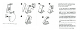
1.1 OperationofAeroDRDetector
1.1.2 AeroDRDetectororientation
Change the orientation of the AeroDR Detector ac-
cording to the exposure body part.
Expose with the mark upward when exposing in por-
trait, and with the mark to the side when exposing in
landscape.
O
Whenexposinginportrait
X-ray
X-ray device
The mark is upward
O
Whenexposinginlandscape
X-ray
X-ray device
The mark is to
the left or right
IMPORTANT
•••••••••••••••••••••••••••••••••••••
• The side with the mark is the exposure surface.
• When exposing in landscape, the direction of the
mark is set according to exposure environment.
•••••••••••••••••••••••••••••••••••••••••••••••••••••
1.1.1 Exposure
Exposure with this device is performed with the follow-
ing procedure.
1
Performexamination registration with the
imageprocessingcontroller.
2
Checkthatthisdeviceisready toexpose
images, and then prepare for the expo-
sure.
3
PushtheexposureswitchoftheX-rayde-
vicetoperformtheexposure.
• When the exposure is completed, images are
stored in the AeroDR Detector and will then be
converted to digital data and sent to the image
processing controller sequentially.
4
Check that the exposed image is dis-
playedonthe image processingcontrol-
ler.
HINT
•••••••••••••••••••••••••••••••••••••
• If the AeroDR Detector remains unused for a long time
it transitions to the sleep mode.
• When the image processing controller is ready to ex-
pose, it recovers from the sleep mode.
•••••••••••••••••••••••••••••••••••••••••••••••••••••
Reference
•••••••••••••••••••••••••••••••••••••
• Regarding the operation of the image processing con-
troller, refer to the "Operation Manual" of the image
processing controller.
•••••••••••••••••••••••••••••••••••••••••••••••••••••
Exampleofpagestructure
(1)
(4)(4)
(5)
(3)
(2)
Number Item Description Icon
(1) Item heading Describes the titles of described content. -
(2) Operation procedure
The operating procedure is described in sequential numerical
steps.
-
(3) Hint Describes important information.
HINT
(4) Reference Describes reference items. Refer to these as necessary.
Reference
(5) Important items
Describes the important items for operation. Be sure to read
them.
IMPORTANT

11
Chapter
1
Safety Precautions & Warnings
This chapter describes precautions and warnings
to ensure safe use of this device.

12
1.1.1
Safety alert symbol
This is a "safety alert symbol". This symbol alerts you
to matters and/or operation potentially hazardous to
yourself and other people. Read these messages and
follow the instructions carefully.
1.1.2 Warning notice (signal
words)
Signal words indicate the degree of potential hazards
in the use of the product.
Signal words include the following three types, which
are used according to risk of damage caused by dan-
ger and the severity of damage.
DANGER
Indicates an imminently hazardous situation which, if
not avoided, will result in death or serious injury.
WARNING
Indicates a potentially hazardous situation which, if not
avoided, could result in death or serious injury.
CAUTION
Indicates a potentially hazardous situation which, if
not avoided, could result in minor or moderate injury.
It may also be used to indicate hazardous situation
where only physical damage is likely to occur.
1.1.3 Description of graphic
symbols
Indicates the on position for the main
power switch of this device.
Indicates the position where the ground
is attached.
Indicates a B-type Applied Parts medical
device.
Indicates that full caution is required
when handling this device.
Indicates that it is necessary to read the
User's Manual before use or operation of
this device.
Indicates devices including radio fre-
quency transmitters.
Indicates that the level of water ingress
protection is equivalent to IPX6.
0197
This CE mark on this product indicates
that this product is in conformity with the
applicable requirements set out in the
Directive 93/42/EEC (Medical Device
Directive) and in Directive 2011/65/EU
(RoHS Directive).
0197indicatestheidenticationnumber
ofthenotiedbodyresponsibleonlyfor
implementation of the Directive 93/42/
EEC (Medical Device Directive).
EC Directive 93/42/EEC does not cover
animaluse.So,thenotiedbodywhose
identification number is 0197 is not re-
sponsible for animal use.
It means conformity with the Radio
Equipment and Telecommunications
Terminal Equipment Directive 1999/5/
EC. And the alert sign (!) means that is
categorized Class 2 radio equipment.
1.1 Symbols relating to safety
Indicates the on or standby position for
the power switch of this device.
Indicates the off position for the main
power switch of this device.

13
Chapter 1
1.2 Warning labels
Various warning labels are attached to this device on the locations shown below. Do not remove these labels from this de-
vice. Warning labels are there to make sure that the user recognizes potential hazards when operating this device.
* If a warning label is too dirty or damaged to read, contact Konica Minolta technical representatives to have a new
warning label attached, and redisplay by parts replacement. (There is a fee for this service.)
1.2.1 AeroDR Detector
1.2.2 AeroDR Generator Interface Unit2

14
1.2 Warning labels
1.2.3 AeroDR Battery Charger
1.2.4 AeroDR Battery Charger2

15
Chapter 1
1.3.2 Precautions for usage
WARNING
• The AeroDR Detector is a precision instrument. If it
is dropped or hit against any object, a failure may
occur due to strong impact or excessive load.
• Take note of the following when using this device:
–
Do not subject the AeroDR Detector to strong
shocks or excessive loads by dropping it, etc.
– Donotexceedthespeciedoverallloadrange
when applying a load to an AeroDR Detector.
– Do not disassemble or modify this device.
– Do not connect any devices that were not pur-
chased from Konica Minolta.
– Do not turn the power switch off or pull out the
power cable while the system is operating.
– Be careful not to drop the AeroDR Detector
on any part of a person's body by catching the
AeroDR I/F Cable or AeroDR UF Cable on your
feet.
– Do not lean on or put pressure on the AeroDR
Battery Charger installed on a wall.
• The AeroDR I/F Cable and AeroDR UF Cable are
connected to the AeroDR Detector using magnetic
force. When moving the AeroDR Detector, do
not hold onto the cable, and always hold on the
AeroDR Detector. Also, do not grasp and pull the
AeroDR Detector forcefully.
1.3 Safety precautions
Read all safety precautions thoroughly before using
this device.
Be sure to observe the safety precautions described in
this section.
1.3.1
Precautions before usage
CAUTION
• The operators (hospitals and clinics) hold responsi-
bility for the usage and maintenance of this device.
Do not use this device unless you are a physician
orcertiedpersonunderlaw.
• This device excluding the image processing con-
troller is suitable for use in the patient environment.
(PC used for the image processing controller is not
suitable for use in the patient environment.)
• Confirm that this device is operating normally be-
fore using.
• When a problem occurs with this device, turn
the power off, attach an appropriate sign, such
as "malfunction", on this device, and contact
Konica Minolta technical representatives.
• This device is not explosion-proof, so do not use
anyammableorexplosivegasnearthisdevice.
• For the basic operation of the computer, display
monitor, and optional parts for this device, refer to
their operation manuals.
• Please follow the rules and regulations of your rel-
evant authorities in the disposal of this product, ac-
cessories, options, consumables, media and their
packing materials.
This symbol means: Do not dispose of this
product together with your household waste!
Please refer to the information of your local
community or contact our dealers regarding
the proper handling of end-of-life electric and
electronic equipments.
Recycling of this product will help to conserve
natural resources and prevent potential negative
consequences for the environment and human
health caused by inappropriate waste handling.

1.3 Safety precautions
16
WARNING
• If there is any smoke, odor, or abnormal sound, it
maycauseareifuseiscontinued,soimmediately
turn the power switch off, unplug the power plug
from the wall outlet, and contact Konica Minolta
technical representatives.
• Takenoteofthefollowingtoreducetheriskofre,
electric shock, or electrical leakage:
– Usespeciedcablesforthepowercable,etc.
– Use a wall outlet with the correct rating as a
power source.
– Confirm that the power plug is properly con-
nected to the wall outlet without any slack.
– Use a grounded power source.
– If you do not plan to use this device for an ex-
tended period of time, unplug the power plug.
– The supplied power cable and AC adapter are
dedicated for this device, so do not use it else-
where.
– Avoid exposure to liquid such as water.
– Make sure that foreign material, such as pieces
of metal or wire, does not get inside.
– Do not allow any metal or conductive objects to
come into contact with the spring connector of
the AeroDR Battery Charger2, AeroDR I/F Cable
or AeroDR UF Cable.
– Do not handle the power plug with wet hands.
– Do not let soil or dust accumulate on the power
plug, AeroDR Battery Charger2, AeroDR I/F Cable
or AeroDR UF Cable.
– Do not use extension cords.
– Do not connect many plugs to a single electrical
outlet.
– Do not damage the power cable, AC adapter,
AeroDR I/F Cable, or AeroDR UF Cable. Also,
do not use damaged cables.
– Do not block the ventilation openings.
• If there is any abnormality in appearance such as
deformation of the housing or a crack, stop using
the device immediately and contact Konica Minolta
technical representatives.
CAUTION
• Take note of the following when using this device:
– Do not use devices that emit electromagnetic
waves such as high-frequency therapy equip-
ment, mobile phones, or pocket pagers, close to
this device.
– Take note of the reception status for radios and
TVs near this device, since interference may oc-
cur in them when this device is in use.
– Use under the specified environmental condi-
tions. Failure to do so may result in degradation
of performance or malfunction.
– Limit the duration of continuous use of the
AeroDR 1012HQ in a hot and humid environ-
ment (35 to 37°C/95% or lower) in an incubator
to 25 minutes or less.
– Do not insert the AeroDR 1012HQ into the Aero-
DR Battery Charger because the charger cannot
be used for registration or charging the battery.
– Note that the AeroDR Battery Charger cannot
charge the AeroDR 2 1417S.
CAUTION
• Take the following notes when using the AeroDR
Detector:
– UsetheAeroDRDetectoronaatbase.Ifthe
AeroDR Detector is placed on a sloping surface
and subjected to a load, its internal sensor may
be damaged.
– When laying the patient onto the AeroDR Detec-
tor during positioning, do so very slowly.
– When placing the AeroDR Detector under the
patient as part of the exposure process, insert
and pull out the detector slowly.
– Use the recommended adapter when you need
to perform exposure on a stretcher or a place
where load is to be applied locally.

1.3 Safety precautions
17
Chapter 1
CAUTION
– Exposing or immersing the AeroDR Detector to
patient body fluids, chemicals, water, etc. may
allow such liquids to enter through exterior gaps
and cause a failure. Make sure to cover the
AeroDR Detector with a vinyl sheet, etc.
– Be careful of the ingress of patient body fluids,
chemicals, water, etc., because the AeroDR
1417HQ, AeroDR 1417S, AeroDR 1717HQ, and
AeroDR 1012HQ are not designed to be water-
proof.
– The AeroDR 2 1417HQ and AeroDR 2 1417S are
designed to have waterproof capabilities, but be
careful when handling them because they are not
guaranteed to be completely waterproof. Also,
be careful because subjecting them to strong
impacts or excessive loads by dropping or hitting
them against other objects may diminish their wa-
terproof capabilities.
– Never leave AeroDR Detectors in hot and humid
environments for long periods of time.
– The AeroDR Detector has wireless antennae po-
sitioned at 2 places. Do not block them with the
body or metal because that will interfere with, dis-
connect or slow down wireless communication.
– Pressing the power switch causes each LED
(green, orange, blue) to light temporarily or
ash.Afterthis,onlygreenbeginstoashina
slowcycle.Pleasecheckthelightingorashing
of each color once.
– The battery capacity is designed to allow the life
period calculated based on the standard usage
of the AeroDR Detector. It can be replaced with
a new battery for a fee if replacement is neces-
sary after the warranty period due to battery
breakdown or decrease in capacity.
CAUTION
– Check that the buzzer sounds when mounted on
the AeroDR Battery Charger or AeroDR Battery
Charger2.
– Check that the LED indicates recharging status
when the AeroDR 1417HQ, AeroDR 1417S,
AeroDR 1717HQ, or AeroDR 2 1417HQ is
mounted on the AeroDR Battery Charger.
– Check that the LED indicates recharging status
when mounted on the AeroDR Battery Charger2.
– Be careful not to get your hand caught when
setting the AeroDR Detector into the AeroDR
Battery Charger or AeroDR Battery Charger2.
– If the AeroDR Detector is inserted into the
AeroDR Battery Charger or AeroDR Battery
Charger2, make sure that the AeroDR Battery
Charger or AeroDR Battery Charger2 will not tip
over due to any shock applied to the AeroDR
Detector.
– The AeroDR Detector is precision equipment,
and therefore impact or vibration during radiog-
raphy or image transfer may affect the image
quality. Be careful when handling the AeroDR
Detector during and just after radiography.

1.3 Safety precautions
18
CAUTION
–
Never leave AeroDR Detectors around heat genera-
tors such as electric carpet.
–
Do not damage or deform the AeroDR Detector;
doing so may have an effect on exposed images,
or lead to injury.
–
Do not use a sharp object to operate the switch;
doing so may damage the AeroDR 2 1417HQ and
AeroDR 2 1417S.
–
WhenusingatooltoafxtheAeroDRGripsheet
or perform replacement, be careful not to get in
-
jured by a tip or edge of the tool.
• When using the AeroDR I/F Cable or AeroDR UF
Cable, observe the following:
– Remove the cable by holding the connector
housing.
– Do not let the cable get pinched by doors and do
not place heavy objects on it.
– Do not bend or pull the cable excessively.
– Make sure that the cable is properly connected
to the AeroDR Detector without wobbling.
– Do not connect the connector housing back-
wards.
• Do not sit on or put your feet on the AeroDR Bat-
tery Charger or AeroDR Battery Charger2.
• Take note of the following if the AeroDR Detector
isdamagedanduorescentmediumorleadisex-
posed:
– Immediately stop using the device, and contact
Konica Minolta technical representatives.
– Iftheuorescentmediumgetsinyoureyes,do
not rub and instead wash with running water im-
mediately.
– If you have swallowed any of the fluorescent
mediumoriftheuorescentmediumhasgotten
intoyoureyes,administerrst-aidtreatmentim-
mediately, and consult a doctor.
– If the medium comes into contact with your skin
directly, wash the affected area thoroughly with
water.
– Use and store in a location inaccessible to chil-
dren.
• When the AeroDR Detector is used for exposure,
pay attention to the following items.
– Startexposureafterconrmingonthedisplayof
the image processing controller that the machine
is ready for exposure.
– Perform exposure under the X-ray imaging con-
ditionsthathasbeenconrmedbyus.
– Usethespeciedgridtoperformexposure.
– Apply the specified operation methods to use
the grid.
– Do not let the AeroDR Detector vibrate or re-
ceive shock until the preview image is displayed.
CAUTION
• Precautions when performing exposure in
Aero Sync mode.
– Conrmthattheimageprocessingcontrolleris
ready for exposure through its display before
performing exposure.
– Conrmthataconrmationissoundedfromthe
image processing controller after the start of ex-
posure.
– Do not let the AeroDR Detector vibrate or re-
ceive shock until the preview image is displayed.
– ConrmthattheAeroDRDetector'sbatterylevel
is full before performing exposure.
– Use the system under the exposure condition
conrmedpriortoexposure.
• If there are any radioactive substances remaining in
the patient's body after nuclear medicine testing or
some other reason, the AeroDR 2 1417HQ and the
AeroDR 2 1417S may recognize that X-rays were
emitted and start image transfer. When the image
is transferred, change the X-ray sensitive setting
of the image processing controller to "High" before
performing exposure.
If you change the X-ray sensitivity to "High", make
sure that all of the following conditions are met be-
fore performing exposure. If you perform exposure
under other conditions, you may not be able to get
an image.
– On the AeroDR Detector, set up an area (2 cm x
2 cm or larger) on which the X-rays are emitted
directly.
– Emit the X-rays onto the entire AeroDR Detec-
tor.
– Emit the X-rays by using a tube current of 140
mA or higher or a tube voltage of 90 kV or high-
er.
• When setting the maximum exposure time to 4.0,
6.7, 10.3, be sure to contact Konica Minolta techni-
cal representatives.

1.3 Safety precautions
19
Chapter 1
1.3.3 Precautions regarding
electromagnetic waves
EMC Statement
This device has been tested and found to comply with
the limits for medical devices in IEC 60601-1-2: 2007.
These limits are designed to provide reasonable pro-
tection against harmful interference in a typical medi-
cal installation. The device generates, uses and can
radiate radio frequency energy and, if not installed and
used in accordance with the instructions, may cause
harmful interference to other devices in its vicinity.
However, there is no guarantee that interference will
not occur in a particular installation.
Whether this device does cause harmful interference
to other devices can be determined by turning this de-
vice off and on. If it causes harmful interference, the
user is encouraged to try to correct the interference by
1 or more of the following measures:
• Reorient or relocate the receiving device.
• Increase the separation between the devices.
• Connect this device into a wall outlet on a circuit differ-
ent from that to which the other devices are connected.
• Contact Konica Minolta technical representatives.
Supplementary information regarding IEC 60601-
1-2: 2007
(1) Take precautions against this device especially re-
garding EMC. Install and put into service according
to the electromagnetic compatibility (EMC) informa-
tion provided in the manual (Table 1 - Table 4).
(2) Do not use mobile phones or pocket pagers in the vicin-
ity of this device. Use of mobile phones or pocket pag-
ers near this device can cause errors in operation due
to electromagnetic wave interference, so such devices
should be turned off in the vicinity of this device.
(3) Cable list
• Power cable (3.048m/3-Wire/No Shielding)
• Ethernet cable (max 100m/100 BASE-TX)
• Ethernet cable (PoE) (30m/No Shielding)
• Various AeroDR I/F Cables
• Various AeroDR UF Cables
• AeroDR Collimator Cable Set
• Various AeroDR XG Cable Sets
(4) The use of accessories, transducers and cables
other than those sold by Konica Minolta, Inc. as
internal components, may result in increased emis-
sions or decreased electromagnetic immunity of
this device.
(5) Do not use this device adjacent to or stacked with
other devices. If adjacent or stacked use is neces-
sary,conrmnormaloperationintheconguration
in which this device will be used.
(6)SpecicationsregardingRFtransmittersfrequency:
• Frequency
– AeroDR SYSTEM:
5150 to 5350MHz, 5470 to 5850MHz
– AeroDR SYSTEM 2:
2412 to 2472MHz
5180 to 5320MHz, 5500 to 5825MHz
• Modulation
– AeroDR SYSTEM:
OFDM
– AeroDR SYSTEM 2:
2412 to 2472MHz: DSSS/CCK/OFDM
5180 to 5320MHz, 5500 to 5825MHz:
OFDM
• Maximum effective radiation power
– AeroDR SYSTEM:
+15dBm
– AeroDR SYSTEM 2:
+10dBm
• This device may be interfered with by other devic-
es that conform to CISPR emission requirements.

20
1.3 Safety precautions
Table 1
Guidelines and manufacture's declaration - electromagnetic emissions
Thisdeviceisintendedforuseintheelectromagneticenvironmentspeciedbelow.
The customer or the user of this device should assure that it is used in such an environment.
Emissions test Compliance Electromagnetic environment - guidelines
RF emissions
CISPR 11
Group 1
The device uses RF energy only for its internal function. Therefore, its RF
emissions are very low and are not likely to cause any interference in nearby
electronic equipment.
RF emissions
CISPR 11
Class B
This device is suitable for use in all establishments including the following:
Domestic establishments and those directly connected to the public low-
voltage power supply network that supplies buildings for domestic purposes.
Harmonic emissions
IEC 61000-3-2
Class A
Voltageuctuations/
ickeremissions
IEC 61000-3-3
Complies
Table 2
Guidelines and manufacturer's declaration - electromagnetic immunity
Thisdeviceisintendedforuseintheelectromagneticenvironmentspeciedbelow.
The customer or the user of this device should assure that it is used in such an environment.
Immunity test IEC 60601 test level Compliance level
Electromagnetic environment -
guidelines
Electrostatic discharge
(ESD)
IEC 61000-4-2
± 6 kV contact ± 6 kV contact
Floors should be wood, concrete or
ceramictile.Ifoorsarecoveredwith
synthetic material, the relative humidity
should be at least 30%. Mains power
quality should be that of a typical com-
mercial or hospital environment.
± 8 kV air ± 8 kV air
Electrical fast transient/
burst
IEC 61000-4-4
± 2 kV for power supply
lines
± 2 kV for power supply
lines
± 1 kV for input/output
lines
± 1 kV for input/output
lines
Surge
IEC 61000-4-5
± 1 kV differential mode ± 1 kV differential mode
Mains power quality should be that of a
typical commercial or hospital environ-
ment.
± 2 kV common mode ± 2 kV common mode
Voltage dips, short
interruptions and
voltage variations on
power supply input lines
IEC 61000-4-11
<5% U
T
(>95% dip in U
T
)
for 0.5 cycle
<5% U
T
(>95% dip in U
T
)
for 0.5 cycle
Mains power quality should be that of a
typical commercial or hospital environ-
ment. If the user of the device requires
continued operation during power mains
interruptions, it is recommended that the
device be powered from an uninterrupted
power supply or a battery.
40% U
T
(60% dip in U
T
)
for 5 cycles
40% U
T
(60% dip in U
T
)
for 5 cycles
70% U
T
(30% dip in U
T
)
for 25 cycles
70% U
T
(30% dip in U
T
)
for 25 cycles
<5% U
T
(<95% dip in U
T
)
for 5 sec
<5% U
T
(<95% dip in U
T
)
for 5 sec
Power frequency
(50/60 Hz) magnetic
eld
IEC 61000-4-8
3 A/m 3 A/m
Powerfrequencymagneticeldsshould
be at levels characteristic of a typical lo-
cation in a typical commercial or hospital
environment.
[NOTE] U
T
is the AC mains voltage prior to application of the test level.
Page is loading ...
Page is loading ...
Page is loading ...
Page is loading ...
Page is loading ...
Page is loading ...
Page is loading ...
Page is loading ...
Page is loading ...
Page is loading ...
Page is loading ...
Page is loading ...
Page is loading ...
Page is loading ...
Page is loading ...
Page is loading ...
Page is loading ...
Page is loading ...
Page is loading ...
Page is loading ...
Page is loading ...
Page is loading ...
Page is loading ...
Page is loading ...
Page is loading ...
Page is loading ...
Page is loading ...
Page is loading ...
Page is loading ...
Page is loading ...
Page is loading ...
Page is loading ...
Page is loading ...
Page is loading ...
Page is loading ...
Page is loading ...
Page is loading ...
Page is loading ...
Page is loading ...
Page is loading ...
Page is loading ...
Page is loading ...
Page is loading ...
Page is loading ...
Page is loading ...
Page is loading ...
Page is loading ...
Page is loading ...
Page is loading ...
Page is loading ...
Page is loading ...
Page is loading ...
Page is loading ...
Page is loading ...
Page is loading ...
Page is loading ...
Page is loading ...
Page is loading ...
Page is loading ...
Page is loading ...
Page is loading ...
Page is loading ...
Page is loading ...
Page is loading ...
Page is loading ...
Page is loading ...
Page is loading ...
Page is loading ...
Page is loading ...
Page is loading ...
Page is loading ...
Page is loading ...
Page is loading ...
Page is loading ...
Page is loading ...
Page is loading ...
Page is loading ...
Page is loading ...
Page is loading ...
Page is loading ...
Page is loading ...
Page is loading ...
Page is loading ...
Page is loading ...
Page is loading ...
Page is loading ...
Page is loading ...
Page is loading ...
Page is loading ...
Page is loading ...
Page is loading ...
Page is loading ...
Page is loading ...
Page is loading ...
Page is loading ...
Page is loading ...
Page is loading ...
Page is loading ...
Page is loading ...
Page is loading ...
/