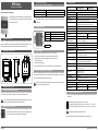
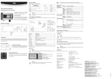
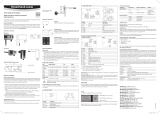
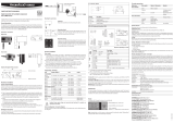
Rotronic PF1 is state-of-the-art transmitter for monitoring and control of differential pressure. The robust construction with IP65 protection makes it ideal for ambitious applications in industrial environments. It is equipped with a variety of output signals, configurable via DIP switch, so that it can be flexibly adapted to different requirements. The maintenance-free PF1 differential pressure transmitter is factory-calibrated for highest accuracy and long-term stability. With its compact design, it can be mounted directly on a DIN rail with the optional mounting kit.
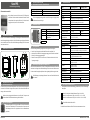
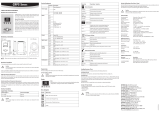
Rotronic PF1 is state-of-the-art transmitter for monitoring and control of differential pressure. The robust construction with IP65 protection makes it ideal for ambitious applications in industrial environments. It is equipped with a variety of output signals, configurable via DIP switch, so that it can be flexibly adapted to different requirements. The maintenance-free PF1 differential pressure transmitter is factory-calibrated for highest accuracy and long-term stability. With its compact design, it can be mounted directly on a DIN rail with the optional mounting kit.


-
 1
1
-
 2
2
-
 3
3
-
 4
4


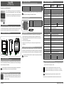
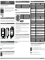
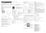
Rotronic PF1 is state-of-the-art transmitter for monitoring and control of differential pressure. The robust construction with IP65 protection makes it ideal for ambitious applications in industrial environments. It is equipped with a variety of output signals, configurable via DIP switch, so that it can be flexibly adapted to different requirements. The maintenance-free PF1 differential pressure transmitter is factory-calibrated for highest accuracy and long-term stability. With its compact design, it can be mounted directly on a DIN rail with the optional mounting kit.
Ask a question and I''ll find the answer in the document
Finding information in a document is now easier with AI
in other languages
- italiano: Rotronic PF1
- français: Rotronic PF1
- Deutsch: Rotronic PF1
Related papers
-
 Rotronic PF4 Short Instruction Manual
-
 Rotronic CRP5 User manual
-
 Rotronic HF56 User manual
-
 Rotronic HS5 Short Instruction Manual
-
 Rotronic AF1 Short Instruction Manual
-
 Rotronic PCDS User manual
-
 Rotronic HF4 User manual
-
 Rotronic HF5NEW User manual
-
 Rotronic HF8 Short Instruction Manual
-
 Rotronic HF1 User manual


Other documents
-
birddog PF120 Full NDI Box Camera User guide
-
WIKA A2G-45 Operating instructions
-
Johnson Controls SDP2500 User manual
-
ABB 266M R Series Short Form Instruction Manual
-
ABB 266PSH Operating Instructions Manual
-
OJ Electronics PTH-3502 Operating instructions
-
-
Johnson Controls DP2500-R8 Installation Instructions Manual
-
-
SkyLink 100PA User manual