Page is loading ...

12.0902.0004
ROTRONIC AG, CH-8303 Bassersdorf
Tel. +41 44 838 11 44, www.rotronic.com
ROTRONIC Messgeräte GmbH, D-76275 Ettlingen
Tel. +49 7243 383 250, www.rotronic.de
ROTRONIC SARL, 56, F - 77183 Croissy Beaubourg
Tél. +33 1 60 95 07 10, www.rotronic.fr
ROTRONIC Italia srl, I- 20157 Milano
Tel. +39 2 39 00 71 90, www.rotronic.it
ROTRONIC Instruments (UK) Ltd, West Sussex RH10 9EE
Phone +44 1293 571000, www.rotronic.co.uk
ROTRONIC Instrument Corp, NY 11788, USA
Phone +1 631 427-3898, www.rotronic-usa.com
ROTRONIC Canada Inc.,Canada L8W 3P7
Phone + 1 905 754 5164, www.rotronic.ca
ROTRONIC Instruments Pte. Ltd., Singapore 159836
Phone +65 6376 2107, www.rotronic.sg
ROTRONIC Shanghai Rep. Office, Shanghai 200233, China
Phone +86 40 08162018, www.rotronic.cn
A
Digital transmitter for humidity & temperature
Congratulations on your purchase of the new state-of-the-art HygroFlex8-series transmitter. Please
read these short instructions carefully before installing the device.
General description
The HygroFlex8-series devices are universal transmitters for transmission of humidity and tempera-
ture measurements. Compatible with all interchangeable HC2 probes. These short instructions are
limited to a description of the main functions and installation of the device. The detailed instruction
manual can be found on the internet at: www.rotronic.com
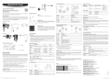
Dimensions / Connections
Wall version
Measured Parameters
HygroClip2 probe:
Humidity and temperature. The HC2 probes measure relative humidity with a ROTRONIC Hygromer
®
IN1 capacitive sensor and temperature with a Pt100 RTD.
Analog probe (general):
Any parameter measured by the probe. The parameter unit must be specied with the HW4 software
(Device Manager). Analog pressure probe: the unit used for barometric pressure is set with the
HW4 software > Device Manager > Unit System.
Probe inputs
The HF8 has two probe inputs. Using the HW4 software (Device Manager), each probe input can
be congured to accept one of the following:
HygroClip2 humidity-temperature digital probe:
Both inputs can be congured to read and display digital signal of a HygroClip2 probe.
1-channel analog probe (general):
To be compatible with the HF8 the analog probe must meet the following requirements: supply
voltage: max. 5 VDC, current consumption: max. 10 mA, output signal: 0 to max. 3.3 VDC. The HF8
uses a 12-bit A/D converter to digitize the probe analog signal and can be congured to measure
practically any parameter.
Analog pressure probe:
This is a special case of analog probe and is subject to the same compatibility requirements. When
analog pressure probe is selected, the HF8 automatically uses the signal from the probe to calculate
any humidity parameter that requires barometric pressure as an input value (example: mixing ratio).
AC5005 Mounting ange
for 15 mm probe
Service interface
Digital connection
Mounting the wall version
Alignment
Mount the transmitter so that the probe points down.
Mounting variant 1
Drill the necessary holes using the drill template drawn on the
packaging. Then insert the plugs delivered with the device and
mount the transmitter with the screws.
Mounting variant 2
If there is a TS35 DIN top-hat rail available, the transmitter can be
clipped on to the top-hat rail directly with the help of the mounting
kit AC5002 (available as optional extra). For this, the DIN holders
(a kit has two holders and eight screws) are screwed directly on to
the predrilled holes in the transmitter.
Electrical installation
Power supply
a) HF831 - HF835: 15 to 40 VDC or 12 to 28 VAC
b) HF841 - HF845 (galvanic separated): 9 to 36 VDC or 7 to 24 VAC
c) HF861 - HF865: 85 to 265 VAC
Note: depending on the type of output signal, the HF8 will operate with the following
minimum voltage
0…1 V outputs 5 VDC or 5 VAC
0…5 V outputs 10 VDC or 8 VAC
0…20 mA or 4 …20 mA outputs 6 VDC or 5 VAC with 0 ohm load
15 VDC or 12 VAC with 500 ohm load
Typical maximum current consumption
Model with 4 analog outputs 150 mA
Model with 4 relay contacts 150 mA
Model with Ethernet (TCP/IP) interface 300 mA
Supply voltage / Technology
Type Supply voltage V+ Load Output
HF831 15…40 VDC / 12…28 VAC Max 500 Ω 0...20 mA
HF832 15…40 VDC / 12…28 VAC Max 500 Ω 4...20 mA
HF833 15…40 VDC / 12…28 VAC Min 1000 Ω 0...1 V
HF834 15…40 VDC / 12…28 VAC Min 1000 Ω 0...5 V
HF835 15…40 VDC / 12…28 VAC Min 1000 Ω 0...10 V
Type Supply voltage V+ Load Output
HF841 9…36 VDC / 7…24 VAC Max 500 Ω 0...20 mA
HF842 9…36 VDC / 7…24 VAC Max 500 Ω 4...20 mA
HF843 9…36 VDC / 7…24 VAC Min 1000 Ω 0...1 V
HF844 9…36 VDC / 7…24 VAC Min 1000 Ω 0...5 V
HF845 9…36 VDC / 7…24 VAC Min 1000 Ω 0...10 V
HF861 85...265VAC Max 500 Ω 0...20 mA
HF862 85...265VAC Max 500 Ω 4...20 mA
HF863 85...265VAC Min 1000 Ω 0...1 V
HF864 85...265VAC Min 1000 Ω 0...5 V
HF865 85...265VAC Min 1000 Ω 0...10 V
Caution: Wrong supply voltages and excessively high loading of the outputs can
damage the transmitter.
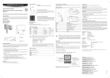
Terminal conguration / Connection diagrams
The type is dened using the table Supply voltage / Technology to then use the following connec-
tion diagrams:
Terminal block diagram (all HF8 models)
Terminal Block K6 Description
K6-1: – Power supply: VDC (-) or VAC (neutral)
K6-2: + Power supply: VDC (+) or VAC (Phase)
K6-3: Protective ground (see note below)
Terminal Blocks K1 and K2 Description Standard output
K1-1: GND Output signal 1 (–)
K1-2: GND Output signal 2 (–)
K1-3: GND Output signal 3 (–)
K1-4: GND Output signal 4 (–)
K2-1: OUT 1 Output signal 1 (+) Humidity*
K2-2: OUT 2 Output signal 2 (+) Temperature**
K2-3: OUT 3 Output signal 3 (+) Humidity*
K2-4: OUT 4 Output signal 4 (+) Temperature**
Terminal Block K3 (RS-485) Description
K3-1: V+ VDC (+), when HF8 is powered from RS-485 data cable
K3-2: GND VDC (-), when HF8 is powered from RS-485 data cable
K3-3: D+ RS-485 +
K3-4: D– RS-485 –
Relay 1 2 3 4
Terminal Block K7 K8 K4 K5
NC: Normally closed (relay not energized) K7-1 K8-1 K4-1 K5-1
COM: Common K7-2 K8-2 K4-2 K5-2
NO: Normally open (relay not energized) K7-3 K8-3 K4-3 K5-3
* For humidity and calculated value output settings:
OUT2/4 = calculated value, OUT1/3 = humidity
** For temperature and calculated value output settings:
OUT1/3 = calculated value, OUT2/4 = temperature
Terminal K6-3: Protective ground is usually connected to GND. If this is not wanted, a link on
the PCB (B2) must be removed.
Terminals K3 (RS-485): Terminals K3-1 and K3-2 can be used to feed the device (multi-point
connection). Several RS-485 devices can be operated with a strong 15 VDC power supply unit. In
this case the supply voltage at K6-1 to K6-3 is not used.
Warning: Make sure that all settings have been made correctly before integrating and connecting
the transmitters in the network.
Programming
The basic settings of the devices are made in the factory according to your order. The transmit-
ters are adjusted in the factory and therefore do not need to be checked and readjusted during
installation. The devices can be started immediately after installation.
SHORT INSTRUCTION MANUAL
Current output
Voltage output
Relay Digital Analog
102
192
85
52
=
~
K6-2:
DC+/AC L
K6-1:
DC −/AC N
K1: GND
K2: OUT2...4
K2: OUT1
K1: GND
K2: OUT2...4
K2: OUT1
K6-2:
DC+/AC L
K6-1:
DC −/AC N
1) RXD (UART digital probe)
2) GND (digital and power)
3) V+: digital probes: 3.3 VDC nominal, analog probes: max. 5.0 VDC, 10 mA
4) AGND (analog ground)
5) Not used
6) One-channel analog probe signal: +0.0 to 3.3 VDC
7) TXD (UART digital probe)
Pin-Out Diagram
Mechanical installation
General recommendations
Relative humidity is extremely temperature-dependent. In order to measure it exactly, the probe and
sensors must be set exactly on the temperature level of the environment that is to be measured.
The installation site can therefore have a signicant inuence on the performance of the device.
Follow the guidelines below to ensure optimum performance:
a) Select a representative installation site: Install the probe at a point where the humidity, tempe-
rature and pressure conditions are representative for the environment that is to be measured.
b) Make sure there is sufcient air movement around the probe: An air ow of at least 1 meter/
second accelerates and facilitates adjustment of the probe to changing temperatures.
c) Avoid:
1. Probe too close to heating elements, cooling coils, cold or hot walls, direct sunlight, etc.
2. Probe too close to steam, injectors, humidiers or direct precipitation.
3. Unstable pressure conditions with high air turbulence.
d) Insert the probe as far as possible into the environment that is to be measured.
e) Avoid accumulation of condensation at the contact wires of the sensor. Install the probe so
that the tip points down. If that is not possible, install it in horizontal position.
Mounting with separated probe
To avoid measurement errors, at least 200 mm of the probe should be inserted into the environ-
ment that is to be measured. If necessary, use the mounting ange AC5005 to install the probe.
Power
Supply
Display modes
The LC display has a backlight which can be set to be on all the time or whenever a key is pressed.
The backlight can also be disabled.
Using the HF8 Menu > Device Settings > Display Settings, the display mode can be changed as
shown below:
Standard 3-line display Large
%RH
Temperature
Date and time
%RH
Temperature
Calculated parameter
No date and time
Both the parameter and
probe can be changed
with the UP arrow key or
the DOWN arrow key
The display can also be congured to show a trend indicator on each line:
▲ increasing value ▼ decreasing value
In the event of an alarm the symbol [ ! ] appears to the right of the value.
The bottom of the display shows the date and time as well as which probe is currently selected.
Keypad
Unit system
Press the MENU key and select Device Settings > Local Settings > Unit Sys. Press ENTER to activate
the Unit Sys menu item, use the [+] or [-] key to change the unit system. Press ENTER to conrm
and press MENU to exit.
The HW4 software can also be used to change the unit system.
Date and time
Press the MENU key and select Device Settings > Date or Time. Press ENTER to activate either
the Date or the Time menu item. Use the [+] or [-] key to change the Date or the Time. After each
change, the cursor moves to the right. When done, press ENTER to conrm and press MENU to exit.
To change either the date or the time format, Press the MENU key and select Device Settings >
Local Settings > Date Fmt or Time Fmt. Press ENTER to activate either the Date Fmt or the Time Fmt
menu item, use the [+] or [-] key to change the Date or the Time format. When done, press ENTER
to conrm and press MENU to exit.
The HW4 software can also be used to set the clock of the HF8 to the PC date and time.
Select the calculated parameter for a probe input
The calculated parameter is available only when the input is set for a digital HygroClip 2 probe.
Press the MENU key and select Device Settings > Input 1 or Input 2 > Calc. Press ENTER to activate
the Calc sub-menu, use the [+] or [-] key to select the calculated parameter. Press ENTER to conrm
and press MENU to exit.
192
52
16
31
22.3
39.5
MENU
Activates the internal menu. Press this key
again to go back to the previous menu or to
exit the menu.
ENTER ✔
• When the menu is active, use to conrm the
selection of a menu item, effect a change of
settings and conrm any change.
• In the HF8 Standard Mode, use to capture the
current %RH and temperature data to one of
8 data bins.
UP / DOWN + / –
• Changes either the probe or the parameter
being displayed (including the delta probe).
• When the menu is active, use to navigate the
menu, make a selection or change a value.
K 3
V+
GND
485+
485–
1
2
3
4
K 1
K 2
GND
GND
GND
GND
OUT1
OUT2
OUT3
OUT4
1
2
3
4
1
2
3
4
K 4
NO
COM
NC
3
2
1
K 5
NO
COM
NC
3
2
1
K 7
NO
COM
NC
K8
NO
COM
NC
3
2
1
3
2
1
1
2
3
K6
DC–/AC N
DC+/AC L
B2
• •
digital in/output

12.0902.0004
ROTRONIC AG, CH-8303 Bassersdorf
Tel. +41 44 838 11 44, www.rotronic.com
ROTRONIC Messgeräte GmbH, D-76275 Ettlingen
Tel. +49 7243 383 250, www.rotronic.de
ROTRONIC SARL, 56, F - 77183 Croissy Beaubourg
Tél. +33 1 60 95 07 10, www.rotronic.fr
ROTRONIC Italia srl, I- 20157 Milano
Tel. +39 2 39 00 71 90, www.rotronic.it
ROTRONIC Instruments (UK) Ltd, West Sussex RH10 9EE
Phone +44 1293 571000, www.rotronic.co.uk
ROTRONIC Instrument Corp, NY 11788, USA
Phone +1 631 427-3898, www.rotronic-usa.com
ROTRONIC Canada Inc.,Canada L8W 3P7
Phone + 1 905 754 5164, www.rotronic.ca
ROTRONIC Instruments Pte. Ltd., Singapore 159836
Phone +65 6376 2107, www.rotronic.sg
ROTRONIC Shanghai Rep. Office, Shanghai 200233, China
Phone +86 40 08162018, www.rotronic.cn
Trasmettitore digitale per umidità e temperatura
MANUALE D'ISTRUZIONI BREVE
Standard A 3 righe Grande
%u.r.
Temperatura
Data ed orario
%u.r.
Temperatura
Valore calcolato
è possibile modicare
sia il valore visualizzato,
sia la sonda, utilizzando i
tasti ▲ ▼
1) RXD (UART – sonda digitale)
2) GND (digitale e alimentazione)
3) V+: sonda digitale: 3.3 VDC nominale, sonda analogica: max. 5,0 VDC, 10mA
4) AGND (Ground analogico)
5) non utilizzato
6) segnale sonda analogica a 1 canale: da +0,0 a 3,3 VDC
7) TXD (UART – sonda digitale)
Corrispondenza pin
Flangia di montaggio AC5005
per sonda da 15mm
Ci congratuliamo per il Vostro acquisto di un nuovo trasmettitore della Serie HygroFlex8. Avete
acquistato uno strumento al passo con le tecnologie più moderne. Prima di installare lo strumento,
si prega di leggere la presente guida rapida.
Descrizione generale
Gli apparecchi della Serie HygroFlex8 sono trasmettitori universali, per sonde intercambiabili
HC2, per la trasmissione di valori di umidità e temperatura. La presente guida rapida si limita
a descrivere le funzioni principali dello strumento e la sua installazione. Le istruzioni d’uso
dettagliate sono disponibili in Internet all’indirizzo: www.rotronic.com
Dimensioni / connessioni
Parametri misurati
Sonda HygroClip2: umidità e temperatura. Le sonde HC2 standard misurano l’umidità relativa con
un sensore capacitivo ROTRONIC Hygromer
®
IN1 e la temperatura con una Pt100 RTD.
Sonda analogica: è misurabile ogni parametro di una sonda di produttori terzi. Il segnale analogico
deve però rientrare nelle speciche di seguito indicate.
Il parametro misurato deve essere impostato mediante il software HW4.
Sonda analogica di pressione: è possibile impostare l’ingresso mediante il software HW4.
Ingressi per le sonde
L’HF8 dispone di due ingressi sonda impostabili come segue mediante il software HW4
(Device Manager):
HygroClip2 sonda digitale per umidità e temperatura (standard):
possono congurare i due ingressi in modo che il segnale digitale delle sonde Hygroclip2 sia
letto e visualizzato.
Ingresso sonda analogica a 1 canale:
effettuare la lettura di un segnale analogico. Per l’ingresso analogico valgono i seguenti valori:
tensione di alimentazione max. 5 VDC, assorbimento di corrente della sonda collegata max. 10mA,
segnale acquisito 0...3,3 VDC. Un convertitore A/D a 12-bit elabora il segnale.
Entrata analogica sonda pressione:
valgono le stesse indicazioni come al punto precedente e inoltre il valore letto viene utilizzato per
il calcolo dei parametri di umidità assoluta che dipendono dalla pressione.
Interfaccia di servizio
Connessione digitale
102
192
85
52
Installazione meccanica
Consigli generici
L’umidità relativa dipende direttamente dalla temperatura. La sua misurazione esatta richiede
che la sonda e i sensori abbiano esattamente la stessa temperatura dell’ambiente da misurare.
Pertanto la sede di installazione scelta ha un ruolo primario per il rendimento dello strumento.
Per ottenere un rendimento ottimale dello strumento si devono assolutamente rispettare le
seguenti prescrizioni:
a) Selezionare una sede di installazione rappresentativa per le misurazioni: installare la sonda
in un punto dove le condizioni di umidità, temperatura e pressione siano rappresentative per
l’ambiente che si intende misurare.
b) Garantire che la sonda sia sottoposta a sufciente ventilazione: Una velocità dell’aria di almeno
1 metro/secondo velocizza e facilita l’adattamento della sonda alle variazioni di temperatura.
c) Condizioni da evitare:
1. Sonda troppo vicina a elementi riscaldanti, serpentine di raffreddamento, pareti fredde o
calde, esposizione diretta ai raggi solari ecc.
2. Posizionamento della sonda troppo vicino a fonti di vapore, iniettori, umidicatori, spruzzi
d'acqua.
3. Condizioni di pressione instabile e/o eccessive turbolenze dell’aria.
d) Inserire il più possibile la sonda nell’ambiente che si intende misurare.
e) Evitare la formazione di condensa sulle gambe dei sensori. Installare la sonda in modo che la
punta sia rivolta verso il basso, nel caso non sia possibile, installarla in posizione orizzontale.
Montaggio con sonda separata
Per evitare possibili errori di misurazione, si dovrebbero inserire almeno 200 mm della sonda
nell’ambiente da misurare. Utilizzare eventualmente la angia di montaggio AC5005 per installare
la sonda.
192
52
16
31
22.3
39.5
Montage de la version murale
Orientamento
Il trasmettitore va montato in modo che la sonda sia rivolta verso
il basso.
Variante 1 di montaggio
Utilizzando la sagoma di foratura sulla confezione per effettuare i
fori necessari. In seguito si inseriscono i tasselli forniti per montare
il trasmettitore
Variante 2 di montaggio
Se sono presenti barre di montaggio DIN TS35, utilizzando il kit di
montaggio AC5002 (opzionale) è possibile montare il trasmettitore
direttamente sulle barre DIN. A tal scopo si avvitano i supporti
direttamente sui fori predisposti sul trasmettitore.
(una confezione AC5002 contiene 2 supporti e 8 viti).
Installazione elettrica
Tensione di Alimentazione
a) HF831 - HF835: 15 a 40 VDC oppure 12 a 28 VAC
b) HF841 - HF845 (con separazione galvanica): 9 a 36 VDC oppure 7 a 24 VAC
c) HF861 - HF865: da 85 a 265 VAC
Nota: in funzione dei segnali di uscita, l'HF8 dovrà essere alimentato con le seguenti tensioni di
alimentazioni minime:
Uscita 0…1 V 5 VDC o 5 VAC
Uscita 0…5 V 10 VDC o 8 VAC
Uscita 0…20 mA e 4 …20 mA 6 VDC o5 VAC con carico 0 ohm
15 VDC o 12 VAC con carico 500 ohm
Consumo massimo di corrente (tipico)
Modelli con 4 uscite analogiche 150 mA
Modelli con 4 contatti relé 150 mA
Modelli con interfaccia Ethernet (TCP/IP) 300 mA
Tensione di alimentazione / tecnologia
Tipo Tensione di Alimentazione V+ Carico Uscita
HF831 15…40 VDC / 12…28 VAC Max 500 Ω 0...20 mA
HF832 15…40 VDC / 12…28 VAC Max 500 Ω 4...20 mA
HF833 15…40 VDC / 12…28 VAC Min 1000 Ω 0...1 V
HF834 15…40 VDC / 12…28 VAC Min 1000 Ω 0...5 V
HF835 15…40 VDC / 12…28 VAC Min 1000 Ω 0...10 V
Tipo Tensione di Alimentazione V+ Carico Uscita
HF841 9…36 VDC / 7…24 VAC Max 500 Ω 0...20 mA
HF842 9…36 VDC / 7…24 VAC Max 500 Ω 4...20 mA
HF843 9…36 VDC / 7…24 VAC Min 1000 Ω 0...1 V
HF844 9…36 VDC / 7…24 VAC Min 1000 Ω 0...5 V
HF845 9…36 VDC / 7…24 VAC Min 1000 Ω 0...10 V
HF861 85...265 VAC Max 500 Ω 0...20 mA
HF862 85...265 VAC Max 500 Ω 4...20 mA
HF863 85...265 VAC Min 1000 Ω 0...1 V
HF864 85...265 VAC Min 1000 Ω 0...5 V
HF865 85...265 VAC Min 1000 Ω 0...10 V
Attenzione: tensioni di alimentazione errate o carichi eccessivi sulle uscite possono
danneggiare il trasmettitore.
Morsettiere / schemi di collegamento
In base alla tabella “Tensione di alimentazione / tecnologia” si denisce il tipo di trasmettitore e
gli schemi di collegamento da utilizzare:
A
Schemi di collegamento (tutti modello HF8)
Morsetto K6 Descrizione
K6-1: – Alimentation en tension: VCC (-) or VCA (neutre)
K6-2: + Alimentation en tension : VCC (+) ou VCA (phase)
K6-3: Terre (Voir les remarques ci-dessous)
Morsetto K1 e K2 Descrizione Uscita standard
K1-1: GND Segnale uscita 1 (–)
K1-2: GND Segnale uscita 2 (–)
K1-3: GND Segnale uscita 3 (–)
K1-4: GND Segnale uscita 4 (–)
K2-1: OUT 1 Segnale uscita1 (+) Umidità*
K2-2: OUT 2 Segnale uscita 2 (+) Temperatura**
K2-3: OUT 3 Segnale uscita 3 (+) Umidità*
K2-4: OUT 4 Segnale uscita 4 (+) Temperatura**
Morsetto K3 (RS-485) Descrizione
K3-1: V+ VDC (+), quando l'HF8 é alimentato da cavo dati RS-485
K3-2: GND VDC (–), quando l'HF8 é alimentato da cavo dati RS-485
K3-3: D+ RS-485 +
K3-4: D– RS-485 –
Relé 1 2 3 4
Borne K7 K8 K4 K5
NC: Normalmente Chiuso (relé non energizzato) K7-1 K8-1 K4-1 K5-1
COM: Comune/Massa K7-2 K8-2 K4-2 K5-2
NO: Normalmente Aperto (relé non energizzato) K7-3 K8-3 K4-3 K5-3
* Per congurazione uscita umidità e valore calcolato:
OUT2/4 = valore calcolato, OUT1/3 = umidità
** Per congurazione uscita temperatura e valore calcolato:
OUT1/3 = valore calcolato, OUT2/4 = temperatura
Morsetto K6-3: La terra non è collegata come standard a GND. Se non necessario, chiudere il
cavallotto (B2) sulla scheda con una saldatura.
Morsetti K3 (RS-485): per alimentare lo strumento (in connessione multipla) si possono utiliz-
zare i morsetti K3-1 e K3-2 Si possono far funzionare diversi strumenti RS-485 utilizzando un
alimentatore potente da 15VDC. In tal caso l’alimentazione su K6-1 e K6-3 non viene utilizzata.
Avviso: prima di inserire il trasmettitore in rete e di collegarlo, assicurarsi di aver effettuato
correttamente tutte le impostazioni.
Programmazione
Le impostazioni base dello strumento sono effettuate in fabbrica, in conformità con il Vs. ordine.
I trasmettitori sono calibrati in fabbrica e pertanto in fase di installazione non è necessario
effettuare un controllo o una successiva calibrazione. Dopo l’installazione è possibile mettere
immediatamente in funzione gli strumenti.
Uscita di corrente
Uscita di tensione
Relé Digitale Analogica
K1: GND
K2: OUT2...4
K2: OUT1
K6-2:
DC+/AC L
K6-1:
DC −/AC N
Tensione di
Alimentazione
K 3
V+
GND
485+
485–
1
2
3
4
K 1
K 2
GND
GND
GND
GND
OUT1
OUT2
OUT3
OUT4
1
2
3
4
1
2
3
4
K 4
NO
COM
NC
3
2
1
K 5
NO
COM
NC
3
2
1
K 7
NO
COM
NC
K8
NO
COM
NC
3
2
1
3
2
1
1
2
3
K6
DC–/AC N
DC+/AC L
B2
• •
digital in/output
=
~
K6-2:
DC+/AC L
K6-1:
DC −/AC N
K1: GND
K2: OUT2...4
K2: OUT1
Display / modalità di visualizzazione
Il display LCD dispone di una retroilluminazione, impostabile in modo da risultare sempre accesa,
sempre spenta o attivata brevemente alla pressione di un tasto. Le impostazioni si effettuano
nell’HF8 in Menu > Device Settings > Display Settings. Nello stesso menu è possibile impostare
anche la modalità di visualizzazione.
Inoltre a display si possono visualizzare gli indicatori di tendenza dei valori:
▲ Valore in crescita ▼ Valore in diminuzione
In caso di allarme si visualizza il simbolo [ ! ] sul bordo destro del display
Nella parte inferiore del display si visualizzano la data, l’orario e la sonda selezionata. Il simbolo
di un dischetto appare quando la funzione di registraziione é attiva.
Tasti funzione
Unità di misura
In Menu/Device Settings > Local Settings > Unit System è possibile selezionare il sistema di unità
di misura (metrico/inglese), utilizzando i tasti SU / GIÙ. Premendo il tasto ENTER si conferma la
selezione.
Tale funzione è possibile anche utilizzando il software HW4.
Data e ora
In MENU/Device Settings > Date or Time si seleziona l’ora o la data mediante il tasto ENTER. Con i
tasti SU / GIÙ si modicano i valori, confermandoli poi con ENTER. Dopo ogni modica il cursore
si sposta a destra.
è possibile modicare la visualizzazione di data / ora in Device Settings > Local Settings > Date
Fmt o Time Fmt. È possibile utilizzare anche il software HW4 per la modicare l'ora e la data.
Selezione del valore calcolato di una sonda
I parametri calcolati possono essere selezionati solo se è collegata una sonda HygroClip2.
In MENU/ Device Settings > Input 1 o Input 2 > Calc. ENTER si seleziona con i tasti SU / GIÙ il valore
calcolato e poi lo si conferma con ENTER.
MENU
Attiva il menu interno Premendolo nuova-
mente di accede al prossimo menu / si esce
dal menu
ENTER ✔
• Se il menu è attivato, si utilizza il tasto di
Enter per la selezione dei submenu e per la
conferma di eventuali modiche.
• In modalità standard HF8: memorizzazione
dei valori attuali.
SU / GIÙ + / –
• Cambia la sonda o il parametro.
• Se il menu è attivato, si utilizzano le frecce
per la navigazione e per la modifica di
parametri e valori.
/