Page is loading ...

Marine Electrical Prod
ucts
Blue Sea Systems Inc. p 360.738.8230
4600 Ryzex Way f 360.734.4195
Bellingham, WA 98226 USA www.bluesea.com
6343 Rev. 005
WARNING
The Dual Circuit Plus
™
Battery Switch turns the house and start batteries
on at the same time, but isolates them from each other. Battery isolation
protects the start battery from being discharged from the many house loads
like refrigerators, stereos, and lights, preserving it for starting the engine.
Battery isolation also protects sensitive electronics from voltage spikes and
sags that may occur during engine starting. The Dual Circuit Plus
™
Battery
Switch simplies battery switch operation--it performs the same operation
as three ON/OFF battery switches. The engine and house batteries are
turned ON at the same time when the boat is boarded and OFF when the
boat is not in use. This minimizes the opportunity for error. In an emergency
requiring that both batteries be combined—e.g., a discharged start battery—
the operator simply turns the switch knob to the COMBINE BATTERIES
position.
The Dual Circuit Plus
™
Battery Switch automates the charging of two battery
banks when coupled with an Automatic Charge Relay (7610 or 9112). This
combination creates a complete battery management system of isolated
battery circuits, emergency cross connect (emergency parallel) functions,
and automated charge management.
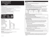
Dual Battery Main Distribution Panel
One Dual Circuit Plus
™
Battery Switch
8686/8690
How it works Installation
1. Disconnect all DC power
To eliminate the possibility of a short circuit while installing the panel,
disconnect the main positive cable from all batteries.
2. Select mounting location and cut opening
Select a mounting location that is protected from water on the panel
front and back and is not in an area where ammable vapors from
propane, gas or lead acid batteries accumulate.
Using the panel template provided, make a cut out in the mounting
surface where the panel is to be mounted. Do not fasten the panel to
the mounting surface.
3. Install LED negative feed wire
Use a 16 AWG wire to connect the LED negative feed (Yellow) wires
to a DC negative bus.
4. Electrical Connections
Battery cable terminals must be attached under battery switch stud
nut and lock washer. The electrical connection illustration is general
in nature and is not meant to be a guide for the wiring of any specic
vessel. There are many possible wiring congurations. Consult your
marine electrical professional for the wiring system applicable to
your boat.
Make appropriate adjustments to the wiring diagram to suit your
specic installation and equipment. Fusing may be appropriate
in several of the lines depending on the proximity of components,
conductor sheathing, and the conductivity of the surrounding structure.
Consult the Wire Sizing Chart to determine the appropriate wire sizes.
5. Apply Labels and Mount Panel
Apply a label to each of the circuits from the label sheet provided.
Additional labels are available from Blue Sea Systems. Fasten the panel
to the mounting surface using the screws provided.
Features
• Power distribution, switching, and circuit protection combined in one panel
• Congurable to suit specic needs of individual boat owners
• Dual Circuit Plus
TM
Battery Switch: m-Series (8686) or e-Series (8690)
• Two 15A thermal circuit breakers provide 24-hour circuit protection
• Each circuit contains circuit labels and LED indicator lights that provide
circuit status
• Blank slots to accommodate additional circuit breakers or switches
Panel Specications
Material: 0.125" 5052-H32 Aluminum Alloy
Primary Finish: Chemical Treatment per MIL SPEC C-5541C
Final Panel Finish: Graphite color 2 part textured Polyurethane
Maximum Voltage Rating: 24V DC
House Amperage Rating: 100A Max (on installed circuit)
8686 8690
Switch Amperage Ratings: Continuous: 300A per circ. 350A per circ.
Intermittent (5 min.): 450A per circ. 525A per circ.
Cranking (30 sec.): 675A per circ. 700A per circ.
Inches Millimeters
Dimensions: 8686 4.50 x 7.50 114.3 x 190.50
8690 5.25 x 8.00 133.35 x 203.20
Mounting Centers: 8686 3.67 x 6.67 93.22 x 169.42
8690 4.42 x 7.17 112.27 x 182.12
Switch Terminal Studs: 3/8"-16 (accepts M10 terminal)
Torque: 140 in-lbs.
If the installer is not knowledgeable about electrical systems,
consult an electrical professional.
If either the panel front or back is to be exposed to water it must be
protected with a waterproof shield.
Standard Blue Sea Systems battery management panels are ignition
protected as shipped.
Custom panels are ignition protected when supplied with ignition
protected circuit breakers.
The main positive connection must be disconnected at the battery post
to avoid the possibility of a short circuit during the installation of
this distribution panel.
Guarantee:
Blue Sea Systems stands behind its products for as long as you own
them. Find detailed information at www.bluesea.com/about. For
customer service, call 800-222-7617.
Applicable Standards
• American Boat and Yacht Council (ABYC) Standards and
Recommended Practices for Small Craft sections: E-1, E-3, E-11.
• United States Coast Guard 33 CFR Sub Part 1, Electrical Systems.
• National Fire Protection Agency (NFPA) 302
Useful Reference Books
• Calder, Nigel (2005). Boatowner’s Mechanical and Electrical Manual
(3d ed). Camden, ME: International Marine / McGraw-Hill.
• Wing, Charlie (2006): Boatowner’s Illustrated Electrical Handbook
(2d ed). Camden, ME: International Marine / McGraw-Hill.
Other Innovative Products from Blue Sea Systems
• 360 Panel System
• Battery management solutions
• AC and DC circuit protection devices
• Water-resistant and waterproof panels
• BusBars, fuses, and fuse blocks
• Analog and digital meters

Wire Sizing Chart
1. Calculate the maximum sustained amperage of the circuit. Measure the
length of the circuit from the power source to the load and back.
2. Calculate Famps (Feet x amps). Multiply circuit length by max. current.
3. Base the wire on either the 3% or 10% voltage drop. In general, items
which affect the safe operation of the boat and its passengers (running
lights, bilge blowers, electronics) use 3%; all other loads use 10%.
4. Are the circuit runs in an engine space or non engine space?
5. Starting in the Famps column with the right voltage and voltage drop,
run down the list until arriving at a value which is greater than the
calculated Famps. Move left to the Ampacity column to verify that the
total amperage of the circuit does not exceed the maximum allowable
amperage of the wire size for that row. If it does, move down until the
wire ampacity exceeds the circuit amperage. Finally, move left to the
wire size column to select the wire size.
Example
A 12 volt system at 10% drop with a 40’ circuit x 45 amps = 1800 Famps.
A wire size of 8 is required.
Note: For wire with 105°C insulation rating and AWG wire sizes.
Chart courtesy of the West Advisor
Caution: ABYC Interrupt
In certain circumstances, main DC circuit breakers may have to break
very high amperages. The ability of a circuit breaker to safely break high
amperage is its Ampere Interrupt Capacity (AIC) rating. AIC is a function
of a battery’s Cold Cranking Amperes (CCA) capacity. According to ABYC
E-11 standards, circuit breakers shall have a DC voltage rating of not less
than the nominal system voltage, be capable of an interrupting capacity
according to the values in the table below, and remain operable after the
fault. For example, a boat with a group 24 or 27 battery may have as much
as 650 CCA. The DC main circuit breaker for this circuit must have an AIC
rating of 1500 Amperes.
Blue Sea Systems Battery Management Panels contain thermal (push
button reset) circuit breakers rated at 15A. These circuit breakers are
suitable for 24-hour circuits connected directly to 12V or 24V battery banks
with CCA capacities less than 660A.
Installation of this panel in systems with battery banks of 660A or higher
should include an additional fuse or circuit breaker of appropriate interrupt
capacity in the line between the battery bank and the pushbutton circuit
breakers to comply with ABYC E-11 and NFPA 302.
DC voltage rating CCA of all
connected
batteries
Ampere Interrupt Capacity (AIC)
Main Circuit
Breaker (Amperes)
Branch Circuit
Breaker(Amperes)
12 Volt and 24 Volt 650 or less 1500 750
651-1100 3000 750
over 1100 5000 2500
32 Volts 1250 or less 3000 1500
over 1250 5000 2500
GND
SI LED
7610 ACR
2
1
12
LEDLEDLEDLED
TO 24 HOUR
CIRCUITS
TO DC HOUSE
DISTRIBUTION
PANEL OR HIGH
AMP DC LOAD
100A
OUTPUT TO
ENGINE
ALTERNATOR
OR STARTER
ENGINE
HOUSE
DC NEGATIVE
DISTRIBUTION BUS
GND
SI LED
7610 ACR
LEDLEDLEDLED
TO 24 HOUR
CIRCUITS
TO DC HOUSE
DISTRIBUTION
PANEL OR HIGH
AMP DC LOAD
100A
OUTPUT TO
ENGINE
ALTERNATOR
OR STARTER
HOUSE
ENGINE
DC NEGATIVE
DISTRIBUTION BUS
LED
1
1 2
2
Wiring Diagram
8686
Wiring Diagram
8690
/