
TA990FXE Setup Manual
FCC Information and Copyright
This equipment has been tested and found to comply with the limits of a Class
B digital device, pursuant to Part 15 of the FCC Rules. These limits are designed
to provide reasonable protection against harmful interference in a residential
installation. This equipment generates, uses, and can radiate radio frequency
energy and, if not installed and used in accordance with the instructions, may
cause harmful interference to radio communications. There is no guarantee
that interference will not occur in a particular installation.
The vendor makes no representations or warranties with respect to the
contents here and specially disclaims any implied warranties of merchantability
or fitness for any purpose. Further the vendor reserves the right to revise this
publication and to make changes to the contents here without obligation to
notify any party beforehand.
Duplication of this publication, in part or in whole, is not allowed without first
obtaining the vendor’s approval in writing.
The content of this user’s manual is subject to be changed without notice and
we will not be responsible for any mistakes found in this user’s manual. All the
brand and product names are trademarks of their respective companies.
Dichiarazione di conformità
sintetica
Ai sensi dell’art. 2 comma 3 del D.M.
275 del 30/10/2002
Si dichiara che questo prodotto è
conforme alle normative vigenti e
soddisfa i requisiti essenziali richiesti
dalle direttive
2004/108/CE, 2006/95/CE e
1999/05/CE
quando ad esso applicabili
Short Declaration of conformity
We declare this product is complying
with the laws in force and meeting all
the essential requirements as specified
by the directives
2004/108/CE, 2006/95/CE and
1999/05/CE
whenever these laws may be applied

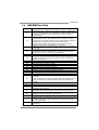
Table of Contents
Chapter 1: Introduction ........................................ 1
1.1 Before You Start ................................................................................ 1
1.2 Package Checklist............................................................................. 1
1.3 Motherboard Features...................................................................... 2
1.4 Rear Panel Connectors ..................................................................... 3
1.5 Motherboard Layout......................................................................... 4
Chapter 2: Hardware Installation .......................... 5
2.1 Installing Central Processing Unit (CPU)....................................... 5
2.2 FAN Headers...................................................................................... 7
2.3 Installing System Memory ................................................................ 8
2.4 Connectors and Slots....................................................................... 10
Chapter 3: Headers & Jumpers Setup .................. 13
3.1 How to Setup Jumpers .................................................................... 13
3.2 Detail Settings.................................................................................. 13
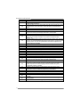
Chapter 4: CrossFireX Function ........................... 20
4.1 CrossFireX Introduction .................................................................. 20
4.2 CrossFireX Configuration ............................................................... 20
Chapter 5: RAID Functions .................................. 21
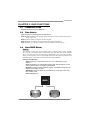
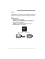
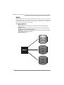
5.1 Operating System............................................................................ 21
5.2 Raid Arrays ...................................................................................... 21
5.3 How RAID Works............................................................................. 21
Chapter 6: T-Series BIOS & Software................... 25
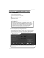
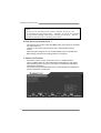
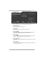
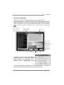
6.1 T-Series BIOS..................................................................................... 25
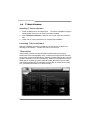
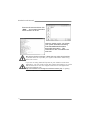
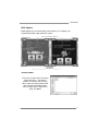
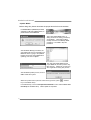
6.2 T-Series Software ............................................................................. 28
Chapter 7: Useful Help ........................................ 38
7.1 Driver Installation Note.................................................................. 38
7.2 Extra Information............................................................................ 39
7.3 AMI BIOS Beep Code....................................................................... 40
7.4 AMI BIOS Post Code ........................................................................ 41
7.5 Conversion Of Hexadecimal and Decimal System...................... 43
7.6 Troubleshooting............................................................................... 44
Appendix: SPEC In Other Languages ................... 46
German.................................................................................................................. 46
French .................................................................................................................... 48
Italian..................................................................................................................... 50
Spanish ................................................................................................................... 52
Portuguese ............................................................................................................ 54
Polish...................................................................................................................... 56
Russian ................................................................................................................... 58
Arabic..................................................................................................................... 60
Japanese ................................................................................................................ 62

TA990FXE
1
CHAPTER 1: INTRODUCTION
1.1 BEFORE YOU START
Thank you for choosing our product. Before you start installing the
motherboard, please make sure you follow the instructions below:
Prepare a dry and stable working environment with
sufficient lighting.
Always disconnect the computer from power outlet
before operation.
Before you take the motherboard out from anti-static
bag, ground yourself properly by touching any safely
grounded appliance, or use grounded wrist strap to
remove the static charge.
Avoid touching the components on motherboard or the
rear side of the board unless necessary. Hold the board
on the edge, do not try to bend or flex the board.
Do not leave any unfastened small parts inside the
case after installation. Loose parts will cause short
circuits which may damage the equipment.
Keep the computer from dangerous area, such as heat
source, humid air and water.
The operating temperatures of the computer should be
0 to 45 degrees Celsius.
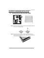
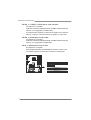
1.2 PACKAGE CHECKLIST
Serial ATA Cable X4
Rear I/O Panel for ATX Case X 1
User’s Manual X1
Fully Setup Driver CD X1
CFX Bridge X2
Note: The package contents may be different due to area or your motherboard version.

Motherboard Manual
2
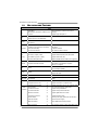
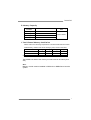
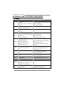
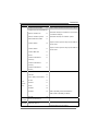
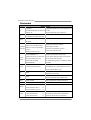
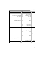
1.3 MOTHERBOARD FEATURES
SPEC
CPU
Socket AM3+
AMD Sempron / Phenom II / Athlon II / FX
processors
AMD 64 Architecture enables 32 and 64 bit
comput ing
Supports Hyper Transport 3.0
FSB
Support HyperTransport 3.0
Supports up to 5.2 GT/s Bandwidth
Chipset
AMD 990FX
AMD SB950
Super I/O
ITE 8728
Provides the most commonly used legacy
Super I/O functionality
Low Pin Count Interface
Environment Control init iatives
H/W Monitor
Fan Speed Contro ller
ITE's "S mart Guardian" funct ion
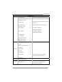
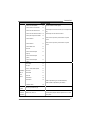
Main
Memory
DDR3 DIMM Slots x 4
Max Memory Capacity 32GB
Each DIMM supports 512MB/
1GB/2GB/4GB/8GB DDR3
Dual Channel Mode DDR3 memory module
Supports DDR3 800/1066/1333/1600/1866
Supports DDR3 2000 (OC)
Registered DIMM and ECC DIMM is not supported
SATA III Integrated Serial ATA Controller
Data transfer rates up to 6 Gb/s.
SATA Vers ion 3.0 specificat ion co mp liant.
RAID 0,1,5,10 support
LAN AR8151 10 / 100 Mb/s / 1Gb/s auto negotiation
Half / Full duplex capability
Sound ALC892 7.1channels audio out
Supports HD Audio
USB3.0 Asmedia ASM1042 Data transfer rates up to 600 MB/s
IEEE 1394 VIA VT6315N 1394a
PCI Slot x2 Supports PCI expansion cards
PCI Express Gen2 x1 Slot x1 Supports PCI-E Gen2 x1 expans ion card
Slots
PCI Express Gen2 x16 Slot x3 Supports PCI-E Gen2 x16,x16, x4, expansion cards
SATA Connector x5 Each connector supports 1 SATA device
Front Panel Connector x1 Supports front panel facilities
Front Audio Connector x1 Supports front panel audio function
S/PDIF out Connector x1 Supports digital audio out function
Consumer IR Connector x1 Supports infrared function
CPU Fan Header x1 CPU Fan power supply (with Smart Fan function)
System Fan Header x2 System Fan Power supply
CMOS clear Header x1 Restore CMOS data to factory default
On Board
Connectors
USB2.0 Connector x2 Each connector supports 2 front panel USB2.0 ports

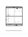
TA990FXE
3
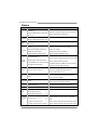
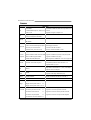
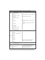
SPEC
USB3.0 Connector x1 Each connector supports 2 front panel USB3.0 ports
IEEE 1394 Connector x1 Connects to IEEE 1394 device
Serial Port Connector x1 Connects to RS-232 Port
Power Connector (24-Pin) x1 Connects to Power supply
Power Connector (8-Pin) x1 Connects to Power supply
Power Connector (4-Pin) x1 Connects to Power supply
Back Panel
I/O
PS/2 Keyboard x1
PS/2 Mouse x1
Optical +coaxial S/PDIF Out x1
1394 Port x1
eSATA Port x1
LAN port x1
USB2.0 Port x4
USB3.0 Port x2
Audio Jack x6
Connects to PS/2 Keyboard
Connects to PS/2 Mouse
Provides digital audio out function
Connects to IEEE 1394 device
Connect to SATA devices
Connect to RJ-45 ethernet cable
Connect to USB2.0 devices
Connect to USB3.0 devices (by Asmedia ASM1042)
and USB2.0/USB1.X devices (by SB950)
Provide Audio-In/Out and Mic. connection
Board Size 305 mm (W) x 244 mm (L) ATX
OS Support
Windows XP / Vista / 7 Biostar reserves the right to add or remove support
for any OS With or without notice.
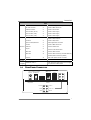
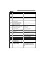
1.4 REAR PANEL CONNECTORS
PS/2
Mou se
PS/2
Keyboard
Line In
Line Out
Mic In
Center
Rear
Side
eSATA
USB3.0X2
LAN
USB2.0X2
IEEE 1394
USB2.0X2
Optical +coaxial
S/PDIF Out

Motherboard Manual
4
1.5 MOTHERBOARD LAYOUT
KBMS1
SPDIF1
USB _1394_
ESATA1
RJ45USB 1
AUDIO1
USB1
ATXPWR2
NB_P H_ LE D
PH1_ D1
PH3_ D3
PH2_ D2
PH4_ D4
Codec
LAN
F_A U DIO1
JSPDIFOUT1
CIR1 J_COM1
SYS_FAN1
F_1394A 1
F_U SB1
F_USB2
JFRONT_US B3_1
JUSBV1
PEX16_1
PEX16_2
PEX16_3
PCI2
PCI1
AUXPWR1
SYS_FAN2
SW_PWR1
SW_R ST1
JUSBV2
PAN EL1
Super
I/O
SATA2
SATA1
SATA3
BIOS
BAT1
JCMOS1
ATXPWR1
DD R3_A1
DD R3_A2
DB2DR3_
DD R3_B1
CPU_FAN1
Socket AM3+
AMD
990FX
AMD
SB950
PEX1_1
Note: represents the 1■st pin.

TA990FXE
5
CHAPTER 2: HARDWARE INSTALLATION
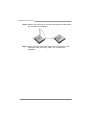
2.1 INSTALLING CENTRAL PROCESSING UNIT (CPU)
Step 1: Pull the lever toward direction A from the socket and then raise the
lever up to a 90-degree angle.
Step 2: Look for the white triangle on socket, and the gold triangle on
CPU should point towards this white triangle. The CPU will fit only
in the correct orientation.

Motherboard Manual
6
Step 3: Hold the CPU down firmly, and then close the lever toward direct
B to complete the installation.
Step 4: Put the CPU Fan on the CPU and buckle it. Connect the CPU
FAN power cable to the CPU_FAN1. This completes the
installation.

TA990FXE
7
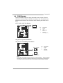
2.2 FAN HEADERS
These fan headers support cooling-fans built in the computer. The fan
cable and connector may be different according to the fan manufacturer.
Connect the fan cable to the connector while matching the black wire to
pin#1.
CPU_FAN1: CPU Fan Header
Pin
Assignment
1 Ground
2 +12V
3 FAN RPM rate
sense
1
4
4 Smart Fan
Control (By Fan)
SYS_FAN1: System Fan Header
SYS_FAN2: NorthBridge Fan Header
Pin Assignment
1 Ground
2 +12V
SYS_FAN2
SYS_FAN1
13
13
3 FAN RPM
rate sense
Note:
CPU_FAN1, SYS_FAN1/2 support 4-pin and 3-pin head connectors. When connecting
with wires onto connectors, please note that the red wire is the positive and should be
connected to pin#2, and the black wire is Ground and should be connected to GND.

Motherboard Manual
8
2.3 INSTALLING SYSTEM MEMORY
A. DDR3 Modules
DDR 3 _A1
DDR 3 _A2
DDR 3 _B1
DB2DR3_
1. Unlock a DIMM slot by pressing the retaining clips outward. Align a
DIMM on the slot such that the notch on the DIMM matches the
break on the Slot.
2. Insert the DIMM vertically and firmly into the slot until the retaining
chip snap back in place and the DIMM is properly seated.

TA990FXE
9
B. Memory Capacity
DIMM Socket
Location DDR3 Module Total Mem ory
Size
DDR3_A1 512MB/1GB/2GB/4GB/8GB
DDR3_A2 512MB/1GB/2GB/4GB/8GB
DDR3_B1 512MB/1GB/2GB/4GB/8GB
DDR3_B2 512MB/1GB/2GB/4GB/8GB
Max is 32GB.
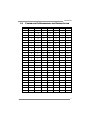
C. Dual Channel Memory Installation
Please refer to the following requirements to activate Dual Channel function:
Install memory module of the same density in pairs, shown in the table.
Dual Channel Status DDR3_A1 DDR3_A2 DDR3_B1 DDR3_B2
Enabled X O X O
Enabled O O O O
(O means memory installed, X means memory not installed.)
The DRAM bus width of the memory module must be the same (x8 or
x16)
Note:
Memory module must be installed in DDR3-A2 or DDR3-B2 to boot the
system.

Motherboard Manual
10
2.4 CONNECTORS AND SLOTS
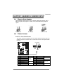
SATA1~SATA3: Serial ATA Connectors
The motherboard has a PCI to SATA Controller with 5 channels SATA interface,
it satisfies the SATA 3.0 spec and with transfer rate of 6.0Gb/s.
Pin
Assignment
1 Ground
2 TX+
3 TX-
4 Ground
5 RX-
6 RX+
147
SATA3
SATA1- SATA2-
1- 2-
UU
SATA L SATA L
7 Ground
AUXPWR1: Auxiliary Power for Graphics
This connector is an auxiliary power connection for graphics cards. Exclusive
power for the graphics card provides better graphics performance.
Pin
Assignment
1 +12V
2 Ground
3 Ground
4 VCC
41
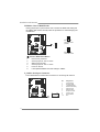
ATXPWR2: AT X Power Source Connector
This connector provides +12V to CPU power circuit. If CPU power plug is 4-pin,
please plug it into Pin 1-2-7-8 of ATXPWR2.
Pin
Assignment
1 +12V
2 +12V
3 +12V
4 +12V
5 Ground
6 Ground
7 Ground
1
45
8
8 Ground

TA990FXE
11
ATXPWR1: AT X Power Source Connector
This connector allows user to connect 24-pin power connector on the ATX
power supply.
1
12
13
24
Pin Assignment Pin Assignment
13 +3.3V 1 +3.3V
14 -12V 2 +3.3V
15 Ground 3 Ground
16 PS_ON 4 +5V
17 Ground 5 Ground
18 Ground 6 +5V
19 Ground 7 Ground
20 NC 8 PW_OK
21 +5V 9 Standby Voltage+5V
22 +5V 10 +12V
23 +5V 11 +12V
24 Ground 12 +3.3V
Note:
Before you power on the system, please make sure that both ATXPWR1 and ATXPWR2
connectors have been plugged-in.
PCI1/PCI2: Peripheral Component Interconnect Slots
PCI stands for Peripheral Component Interconnect, and it is a bus standard for
expansion cards. This PCI slot is designated as 32 bits.
PCI2
PCI1

Motherboard Manual
12
PEX16_1 ~ PEX16_3: PCI-Express Gen2 x16 Slots
- PCI-Express 2.0 compliant.
- Maximum theoretical realized bandwidth of 8GB/s simultaneously per
direction, for an aggregate of 16GB/s totally.
- PCI-Express Gen2 supports a raw bit-rate of 5.0Gb/s on the data pins.
- PEX16_1 & PEX16_2 slots are reserved for graphic or video cards.
PEX16_3: PCI-Express Gen2 x4 Slot
- PCI-Express 2.0 compliant.
- Maximum theoretical realized bandwidth of 2GB/s simultaneously per
direction, for an aggregate of 4GB/s totally.
PEX1_1: PCI-Express Gen2 x1 Slot
- PCI-Express 2.0 compliant.
- Data transfer bandwidth up to 500MB/s per direction; 1GB/s in total.
- PCI-Express supports a raw bit-rate of 2.5Gb/s on the data pins.
PEX16_1
PEX16_3
PEX16_2
PEX1_1

TA990FXE
13
CHAPTER 3: HEADERS & JUMPERS SETUP
3.1 HOW TO SETUP JUMPERS
The illustration shows how to set up jumpers. When the jumper cap is
placed on pins, the jumper is “close”, if not, that means the jumper is
“open”.
Pin opened Pin closed Pin1-2 closed
3.2 DETAIL SETTINGS
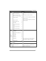
PANEL1: Front Panel Header
This 16-pin connector includes Power-on, Reset, HDD LED, Power LED, and
speaker connection. It allows user to connect the PC case’s front panel switch
functions.
PWR_LED
RST
HLED
SPK
++
+
-
-
1
916
8
On/Off
Pin Assignment Function Pin Assignment Function
1 +5V 9 N/A
2 N/A 10 N/A N/A
3 N/A 11 N/A N/A
4 Speaker
Speaker
Connector
12 Power LED (+)
5 HDD LED (+) 13 Power LED (+)
6 HDD LED (-)
Hard drive
LED 14 Power LED (-)
Power LED
7 Ground 15 Power button
8 Reset control Reset button 16 Ground Power-on button

Motherboard Manual
14
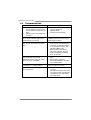
JCMOS1: Clear CMOS Header
Placing the jumper on pin2-3 allows user to restore the BIOS safe setting and
the CMOS data. Please carefully follow the procedures to avoid damaging the
motherboard.
1
3
Pin 1-2 Close:
Normal Operation
(default).
1
3
1
3
Pin 2-3 Close:
Clear CMOS data.
※ Clear CMOS Procedures:
1. Remove AC power line.
2. Set the jumper to “Pin 2-3 close”.
3. Wait for five seconds.
4. Set the jumper to “Pin 1-2 close”.
5. Power on the AC.
6. Load Optimal Defaults and save settings in CMOS.
J_COM1: Serial port Connector
The motherboard has a Serial Port Connector for connecting RS-232 Port.
Pin
Assignment
1 Carrier detect
2 Received data
3 Transmitted data
4 Data terminal ready
5 Signal ground
6 Data set ready
7 Request to send
8 Clear to send
9 Ring indicator
19
210
10 NC

TA990FXE
15
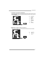
F_AUDIO1: Front Panel Audio Header
This header allows user to connect the front audio output cable with the PC front
panel. This header allows only HD audio front panel connector; AC’97 connector
is not acceptable.
Pin
Assignment
1 Mic Left in
2 Ground
3 Mic Right in
4 GPIO
5 Right line in
6 Jack Sense
7 Front Sense
8 Key
9 Left line in
10 Jack Sense
1
2
9
10
JSPDIFOUT1: Digital Audio-out Connector
This connector allows user to connect the PCI bracket SPDIF output header.
Pin
Assignment
1 +5V
2 SPDIF_OUT
3
1
3 Ground

Motherboard Manual
16
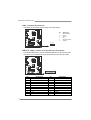
CIR1: Consumer IR Connector
This header is for infrared remote control and communication.
Pin Assignment
1 IrDA serial input
2 Ground
3 Ground
4 Key
5 IrDA serial output
6 IR Power
1
2
5
6
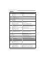
JFRONT_USB3_1: Header for USB 3.0 Ports at Front Panel
This header allows user to connect additional USB cable on the PC front panel,
and also can be connected with internal USB devices, like USB card reader.
1
20 11
10
Pin Assignment Pin Assignment
1 VBUS0 11 D2+
2 SSRX1- 12 D2-
3 SSRX1+ 13 Ground
4 Ground 14 SSTX2+
5 SSTX1- 15 SSTX2-
6 SSTX1+ 16 Ground
7 Ground 17 SSRX2+
8 D1- 18 SSRX2-
9 D1+ 19 VBUS1
10 ID 20 Key

TA990FXE
17
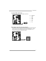
F_1394A1: IEEE 1394 Header
This header allows user to connect IEEE 1394 device.
Pin
Assignment
1 TPA1+
2 TPA1-
3 GND
4 GND
5 TPB1+
6 TPB1-
7 VCC
8 VCC
9 N/A
1
2
9
10
10 KEY
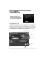
BIOS POST Code/CPU Temperature Indicator
This indicator will show POST code while booting. After the booting sequence,
it will show current CPU temperature through hexadecimal figure. Please
refer to Chapter 7.4 for all the BIOS POST codes, and Chapter 7.5 for
conversion of hexadecimal and decimal system.

Motherboard Manual
18
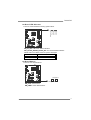
F_USB1/F_USB2: Headers for USB 2.0 Ports at Front Panel
These headers allow user to connect additional USB cable on the PC front panel,
and also can be connected with internal USB devices, like USB card reader.
Pin
Assignment
1 +5V (fused)
2 +5V (fused)
3 USB-
4 USB-
5 USB+
6 USB+
7 Ground
8 Ground
9 Key
12
910
F_USB2 F_USB1
10 NC
JUSBV1/JUSBV2: Power Source Headers for USB Ports
Pin 1-2 Close:
JUSBV1: +5V for USB ports at USB1/USB_1394_ESATA1/RJ45USB1.
JUSBV2: +5V for USB ports at F_USB1/F_USB2/JFRONT_USB3_1.
Pin 2-3 Close:
JUSBV1: +5V STB for USB ports at USB1/USB_1394_ESATA1/
RJ45USB1.
JUSBV2: +5V STB for USB ports at F_USB1/F_USB2/JFRONT_USB3_1.
13
Pin 1-2 close
13
3
1
JUSBV1
JUSBV2
13
Pin 2-3 close
Page is loading ...
Page is loading ...
Page is loading ...
Page is loading ...
Page is loading ...
Page is loading ...
Page is loading ...
Page is loading ...
Page is loading ...
Page is loading ...
Page is loading ...
Page is loading ...
Page is loading ...
Page is loading ...
Page is loading ...
Page is loading ...
Page is loading ...
Page is loading ...
Page is loading ...
Page is loading ...
Page is loading ...
Page is loading ...
Page is loading ...
Page is loading ...
Page is loading ...
Page is loading ...
Page is loading ...
Page is loading ...
Page is loading ...
Page is loading ...
Page is loading ...
Page is loading ...
Page is loading ...
Page is loading ...
Page is loading ...
Page is loading ...
Page is loading ...
Page is loading ...
Page is loading ...
Page is loading ...
Page is loading ...
Page is loading ...
Page is loading ...
Page is loading ...
Page is loading ...
-
 1
1
-
 2
2
-
 3
3
-
 4
4
-
 5
5
-
 6
6
-
 7
7
-
 8
8
-
 9
9
-
 10
10
-
 11
11
-
 12
12
-
 13
13
-
 14
14
-
 15
15
-
 16
16
-
 17
17
-
 18
18
-
 19
19
-
 20
20
-
 21
21
-
 22
22
-
 23
23
-
 24
24
-
 25
25
-
 26
26
-
 27
27
-
 28
28
-
 29
29
-
 30
30
-
 31
31
-
 32
32
-
 33
33
-
 34
34
-
 35
35
-
 36
36
-
 37
37
-
 38
38
-
 39
39
-
 40
40
-
 41
41
-
 42
42
-
 43
43
-
 44
44
-
 45
45
-
 46
46
-
 47
47
-
 48
48
-
 49
49
-
 50
50
-
 51
51
-
 52
52
-
 53
53
-
 54
54
-
 55
55
-
 56
56
-
 57
57
-
 58
58
-
 59
59
-
 60
60
-
 61
61
-
 62
62
-
 63
63
-
 64
64
-
 65
65


Ask a question and I''ll find the answer in the document
Finding information in a document is now easier with AI
Related papers
-
Biostar H61MGC User manual
-
Biostar TA890FXE User manual
-
Biostar TPower X79 Owner's manual
-
Biostar TA870+ User manual
-
-
Biostar TA890GXE User manual
-
Biostar TA870 User manual
-
Biostar TA785G3 HD User manual
-
-

