Page is loading ...

XR Series
LED Remote Displays
Installation Instructions
NORTH AMERICA
AWT35-500303
Issue AD

© Avery Weigh-Tronix, LLC 2012. All rights reserved.
No part of this publication may be reproduced, stored in an electronic retrieval system, or transmitted in any form
or by any means, electronic, mechanical, photocopying, recording or otherwise without the prior written consent of
the copyright owner, or as permitted by law or under license. Full acknowledgment of the source must be given.
Avery Weigh-Tronix is a registered trade mark of the Avery Weigh-Tronix, LLC. This publication was correct at the
time of going to print however, Avery Weigh-Tronix, LLC reserves the right to alter without notice the specification,
design, price or conditions of supply of any product or service at any time.
All third party brands and product names used within this document are trademarks or registered trademarks of
their respective holders.
XR SeriesTD_i_en_500303.book

XR Series Installation Instructions 3
Table of Contents
page
Chapter 1 General information and warnings .........................................................................................5
About this manual ..............................................................................................................5
Installation ..........................................................................................................................6
Electrical installation ..........................................................................................................6
Pluggable equipment ...................................................................................................6
Permanently wired equipment - Isolator requirements ................................................6
Wet conditions .............................................................................................................6
Routine maintenance .........................................................................................................7
Cleaning the machine ........................................................................................................7
Training ..............................................................................................................................7
FCC and EMC declarations of compliance ........................................................................8
Chapter 2 Introduction ..............................................................................................................................9
Display ...............................................................................................................................9
Keypad .............................................................................................................................10
Chapter 3 Installation ..............................................................................................................................11
Installing the XR 4500, XR 4500TL or XR 6500 ..............................................................11
Pre-installation (Receiving Inspection) ......................................................................11
Opening an Enclosure ...............................................................................................11
Lowering the Electronics Plate ..................................................................................12
Mounting Instructions ................................................................................................12
Installing the XR 2000 ......................................................................................................15
Opening the XR 2000 Enclosure ...............................................................................15
Mounting Instructions ................................................................................................15
Chapter 4 Wiring ......................................................................................................................................17
Wiring the XR 4500, 4500TL or 6500 ..............................................................................17
Power Wiring .............................................................................................................17
Communications Wiring ............................................................................................17
Wiring the XR 2000 ..........................................................................................................21
Power Wiring .............................................................................................................21
Communication Wiring ..............................................................................................21
Chapter 5 Wireless Communication ......................................................................................................24
Wireless Set-up for All XR Models ...................................................................................24
XR Remote Display ...................................................................................................24
Indicator .....................................................................................................................24
Base Station Wireless Transceiver ...........................................................................25
Wireless Connection Test ................................................................................................26
Chapter 6 Start-Up ...................................................................................................................................27
Power On/Off ...................................................................................................................27
Reset Button ....................................................................................................................27
Auto-Learn .......................................................................................................................27
LEARN Button ..................................................................................................................28
Diagnostic Indicator Lights ...............................................................................................28
Chapter 7 Configuration Mode ...............................................................................................................30
Entering Configuration Mode ...........................................................................................30
Configuration Parameters ................................................................................................31
Parameter 1.0: Daytime Brightness Level .................................................................31
Parameter 1.1: Nighttime Brightness Level ...............................................................31

4 XR Series Installation Instructions
Parameter 1.2: Power-save Mode .............................................................................31
Parameter 1.3: Mirror Display Mode .........................................................................31
Parameter 1.4: Multi-Drop ID ....................................................................................32
Parameter 1.5: Radio Channel Select .......................................................................32
Parameter 1.6: Utility Program Select .......................................................................32
Auto-Learn Parameters ....................................................................................................33
Parameter 2.0: Manual Learn (Assisted Learn) ........................................................33
Parameter 2.1: Start-up Auto-Learn ..........................................................................33
Parameter 2.2: Leading Zero Suppression ...............................................................33
Parameter 2.3: Set Scale Over .................................................................................34
Parameter 2.4: Lock Units .........................................................................................34
Parameter 2.5: Lock Weighing Mode ........................................................................34
Parameter 2.6: Lock Traffic LIght ..............................................................................34
Time / Date / Temp Parameters .......................................................................................35
Parameter 3.0: Time Display .....................................................................................35
Parameter 3.1: Date Display .....................................................................................35
Parameter 3.2: Temperature Display ........................................................................35
Parameter 3.3: Weight Display ..................................................................................35
Parameter 3.4: Time Threshold .................................................................................35
Diagnostic Parameters .....................................................................................................36
Parameter 9.0: Com Port ..........................................................................................36
Parameter 9.1: String Counter ..................................................................................36
Parameter 9.2: Baud Rate .........................................................................................36
Parameter 9.3: Configuration Lockout .......................................................................36
Parameter 9.4: Number Counter ...............................................................................36
Parameter 9.8: Test Display ......................................................................................37
Parameter 9.9: Reset Defaults ..................................................................................37
CONFIG Switches (XR 2000) ..........................................................................................38
Chapter 8 XR 4500 TL Traffic Light Control ..........................................................................................41
Built-in Traffic Light (XR 4500TL Only) ............................................................................41
Chapter 9 Time and Date (not available on XR 2000) ...........................................................................42
Set Time & Date ...............................................................................................................42
Adjust Time ...............................................................................................................42
Adjust Date ................................................................................................................42
Battery / Battery Replacement .........................................................................................42
Chapter 10 Temperature Probe Installation (not on XR 2000) .............................................................43
Chapter 11 XR Utility Programs .............................................................................................................45
XR 4500, XR 4500TL, and XR 6500 Utility Programs .....................................................45
Program 0: Normal Operation ...................................................................................45
Program 1: Simple Traffic Light .................................................................................45
Program 2: Motion Traffic Light .................................................................................45
Program 3: Normal Operation with Traffic Light Commands .....................................45
Program 4: Freeze Weight (Capture Print String) ....................................................45
Program 5: Command Mode .....................................................................................46
PROGRAM 12: LEGACY COMMAND MODE ..........................................................48
XR 2000 Utility Programs .................................................................................................49
Chapter 12 Troubleshooting & Error Messages ...................................................................................52
Chapter 13 Spare Parts Lists ..................................................................................................................54
Chapter 14 Specifications .......................................................................................................................57

XR Series Installation Instructions 5
1.1 About this manual
1 General information and warnings
1.1 About this manual
This manual is divided into chapters by the chapter number and the large text at the top
of a page. Subsections are labeled as shown by the 1 and 1.1 headings shown above.
The names of the chapter and the next subsection level appear at the top of alternating
pages of the manual to remind you of where you are in the manual. The manual name
and page numbers appear at the bottom of the pages.
Text conventions
Key names are shown in bold and reflect the case of the key being described. This
applies to hard keys and onscreen or soft keys.
Displayed messages appear in bold italic type and reflect the case of the displayed
message.
Special messages
There are five types of special text messages, NOTE, CAUTION, WARNING,
DANGER, and ELECTRICAL HAZARD. Each will appear as illustrated below:
NOTE: This contains extra information on a concept or process.
CAUTION: This may cause damage to the product or data loss.
WARNING: This could result in injury or death
DANGER: THIS WILL RESULT IN INJURY OR DEATH
ELECTRICAL DANGER: THIS WILL RESULT IN INJURY OR DEATH.

6 XR Series Installation Instructions
1 General information and warnings
1.2 Installation
1.3 Electrical installation
1.3.1 Pluggable equipment
Pluggable equipment must be installed near an easily accessible socket outlet.
1.3.2 Permanently wired equipment - Isolator requirements
Permanently connected equipment must have a readily accessible disconnect device
incorporated in the fixed wiring such as an isolator or circuit breaker with at least 3mm
contact separation.
The isolator MUST NOT be installed into the flexible power cable supplied with the unit.
1.3.3 Wet conditions
Under wet conditions, the plug must be connected to the final branch circuit via an
appropriate socket / receptacle designed for washdown use.
Installations within the USA should use a cover that meets NEMA 3R specifications
as required by the National Electrical Code under section 410-57. This allows the unit
to be plugged in with a rain tight cover fitted over the plug.
Installations within Europe must use a socket which provides a minimum of IP56
protection to the plug / cable assembly. Care must be taken to make sure that the
degree of protection provided by the socket is suitable for the environment.
DANGER: RISK OF ELECTRICAL SHOCK. NO USER SERVICEABLE
PARTS. REFER TO QUALIFIED SERVICE PERSONNEL FOR SERVICE.
CAUTION: The power cable must be connected to an earth-grounded electrical
outlet. The electrical supply must have a circuit breaker with an appropriate
rating to protect from over-current conditions.
For your protection, all electrical (110V or 230V) equipment used out of doors or
in wet or damp conditions should be supplied from a correctly fused power
source and protected by an approved ground fault protection device (RCD,
GFCI etc.)
IF IN DOUBT SEEK ADVICE FROM A QUALIFIED ELECTRICIAN.

XR Series Installation Instructions 7
1.4 Routine maintenance
1.4 Routine maintenance
Always turn off the machine and isolate from the power supply before starting any
routine maintenance to avoid the possibility of electric shock.
Make sure that it is placed securely on a flat and level surface.
1.5 Cleaning the machine
1.6 Training
Do not attempt to operate or complete any procedure on a machine unless you have
received the appropriate training or read the instruction books.
To avoid the risk of RSI (Repetitive Strain Injury), place the machine on a surface which
is ergonomically satisfactory to the user. Take frequent breaks during prolonged usage.
IMPORTANT: This equipment must be routinely checked for proper operation
and calibration.
Application and usage will determine the frequency of calibration required for
safe operation.
Table 1.1 Cleaning DOs and DON’Ts
DO DO NOT
Wipe down the outside of standard products
with a clean cloth, moistened with water and
a small amount of mild detergent
Attempt to clean the inside of the machine
Use harsh abrasives, solvents, scouring cleaners or
alkaline cleaning solutions
Spray the cloth when using a proprietary
cleaning fluid Spray any liquid directly on to the display windows

8 XR Series Installation Instructions
1 General information and warnings
1.7 FCC and EMC declarations of compliance
United States
Canada
This equipment has been tested and found to comply with the limits for a Class A digital device, pursuant to Part 15 of the FCC Rules.
These limits are designed to provide reasonable protection against harmful interference when the equipment is operated in a
commercial environment. This equipment generates, uses, and can radiate radio frequency energy and, if not installed and used in
accordance with the instruction manual, may cause harmful interference to radio communications. Operation of this equipment in a
residential area is likely to cause harmful interference in which case the user will be required to correct the interference at his own
expense.
This digital apparatus does not exceed the Class A limits for radio noise emissions from digital apparatus set out in the Radio
Interference Regulations of the Canadian Department of Communications.
Le présent appareil numérique n’émet pas de bruits radioélectriques dépassant les limites applicables aux appareils numériques de
la Classe A prescrites dans le Règlement sur le brouillage radioélectrique edicté par le ministère des Communications du Canada.

XR Series Installation Instructions 9
2.1 Display
2 Introduction
Thank you for purchasing an XR series remote display. The XR series incorporates the
highest performance standards and the most standard features of any weighing
display, making them the best choice for virtually any remote viewing application.
Like all Avery Weigh-Tronix products, the XR remote displays are designed with
durability, functionality and versatility in mind. If you should need technical assistance,
please contact your local, authorized Avery Weigh-Tronix distributor.
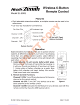
2.1 Display
Figure 2.1 Display samples: Top-XR 4500, Bottom-XR 2000
The weight display is made up of 6 LED digits of 7 segments each. Up to 2 decimal
places can be displayed. (Five decimals on the XR 2000).
ATTENTION! Unauthorized installation and service of this unit may void the
warranty.

10 XR Series Installation Instructions
2 Introduction
The units have four annunciators under the display with bright LED markers:
lGR = Gross Weighing Mode
lNT = Net Weighing Mode
llb = Pounds
lkg = Kilograms
2.2 Keypad
All models of the XR, except the XR 2000, have a keypad on the bottom of the unit. See
illustration of the keypad in Figure 2.2.
Figure 2.2 Keypad
The keypad has three pushbuttons or keys and a light sensor window. Use the keys to
set time and date and to access the configuration mode. The light sensor controls the
brightness of the LEDs based on ambient light levels.

XR Series Installation Instructions 11
3.1 Installing the XR 4500, XR 4500TL or XR 6500
3 Installation
3.1 Installing the XR 4500, XR 4500TL or XR 6500
3.1.1 Pre-installation (Receiving Inspection)
It is always good practice to verify that the unit is complete and undamaged upon
receipt.
lCheck over packaging for any signs of damage.
lRemove the XR from its protective packaging and check for damage.
lVerify that the shipment includes:
mCorrect XR remote display (complete and intact, with power cord).
mInstallation and Technical Instructions.
lDisplays ordered with the wireless option should include:
mRadio module
mExternal antenna
mInternal antenna cable
mBase station kit
mFCC/IC sticker
3.1.2 Opening an Enclosure
1. Make sure the unit is disconnected from power.
2. Remove the Phillips head screws from each side of the enclosure.
3. Slowly, guide the front cover off of the main enclosure. See Figure 3.1.
Figure 3.1 Opening the XR 4500 / 4500TL / 6500 (side view)

12 XR Series Installation Instructions
3 Installation
3.1.3 Lowering the Electronics Plate
1. Remove the three (3) captive screws holding the electronics plate to the main
enclosure. See Figure 3.2.
Figure 3.2 Open enclosure
2. Slowly, allow the electronics plate to swing down. The controller board and
power supply board are now accessible for installation, wiring and service.
See Figure 3.3.
Figure 3.3 Electronics plate down
3.1.4 Mounting Instructions
1. Inspect the installation site for properly grounded power. The outlet must be
installed near the XR and easily accessible.
2. Ensure that mounting structures (walls, pole brackets, etc.) will bear the weight
of the display (XR 4500: 20 lbs, XR 6500 & 4500TL: 28 lbs).
3. Allow proper clearance for lowering and removing the electronics carriage.
4. Use proper hardware, including wall anchors where necessary, when
mounting the enclosure. Secure the main enclosure to wall or pole mounted
bracket with 5/16ths bolts.
Captive Screws

XR Series Installation Instructions 13
3.1 Installing the XR 4500, XR 4500TL or XR 6500
5. Run power and communication cables into the enclosure via strain reliefs (as
required).
Wall Mounting
Hole patterns for the XR series are given in Figure 3.4 and Figure 3.5.
Figure 3.4 XR 4500 Outline dimensions and hole pattern
Figure 3.5 XR 4500TL and XR 6500 Outline dimensions and hole pattern
Pole Mounting Bracket
1. Select appropriate height and fasten the small “C” bracket to the pole using the
mounting clamps provided.
2. Fasten the larger “C” bracket to the small “C” bracket using the hardware
provided.
The electronics carriage may be removed to reduce weight when installing.
Mounting hole size in the case is 3/8”.
Dia: .375in.[9.5mm]
24.00in.[609.6mm]
23.00in.[584.2mm]
10.125in.[257.2mm]
8.88in.[225.6mm]
6.00in.[152.4mm]
3.5in.[89mm]
3.5in.[89mm]
Dia: .375in.[9.5mm]
32.00in.[812.8mm]
31.00in.[787.4mm]
13in.[330.2mm]
11.75in.[298.4mm]
7.75in.[196.9mm]

14 XR Series Installation Instructions
3 Installation
3. Fasten the XR display to the pole mounting bracket as outlined in the
mounting instructions (See Figure 3.6).
Figure 3.6 Pole mounting bracket
Visor Option
1. Loosen the mounting hardware on the main enclosure 1/8th inch.
2. Rest the visor’s mounting brackets on the bolt between the bolt head and the
front of the side mounting plates.
3. Re-tighten the mounting hardware.
Figure 3.7 Optional visor
The pole mounting bracket allows use of poles or beams up to eight inches in
diameter.

XR Series Installation Instructions 15
3.2 Installing the XR 2000
3.2 Installing the XR 2000
3.2.1 Opening the XR 2000 Enclosure
1. Make sure the unit is disconnected from power.
2. Remove the 6 screws (with sealing washers) from the front of the enclosure.
3. Guide the front panel away from the main enclosure. Be sure to watch the
internal cable connections! See Figure 3.8
Figure 3.8 XR 2000 enclosure laid open
3.2.2 Mounting Instructions
1. Inspect the installation site for properly grounded power.
2. Ensure that mounting structures (walls, posts, etc.) will bear the weight of the
display (XR 2000: 6 lbs).
3. Use proper hardware, including wall anchors where necessary, when
mounting the enclosure. Secure the main enclosure to wall or pole mounted
bracket with 5/16ths bolts.
4. Run power and communication cables into the enclosure via strain reliefs (as
required).
Mounting hole size in the case is 5/16”.

16 XR Series Installation Instructions
3 Installation
Figure 3.9 XR 2000 dimensions

XR Series Installation Instructions 17
4.1 Wiring the XR 4500, 4500TL or 6500
4Wiring
4.1 Wiring the XR 4500, 4500TL or 6500
4.1.1 Power Wiring
XR displays are wired for power at the factory. The factory supplied power cable can
be removed for direct AC wiring if necessary.
4.1.2 Communications Wiring
All communications wiring terminates at the controller board. Communications should
be wired before applying power to the unit.
Figure 4.1 Communication terminals
RS 232 Wiring
Terminate the indicator’s communication wires at the RS 232 terminal (J3), shown in
Figure 4.1.
See the table below for pin assignments:
J3 J4 J5
20mA
Mode
Switch
(SW10)
INDICATOR TO XR
TRANSMIT (TX) RECEIVE (RX)
RECEIVE (RX) NO CONNECTION
SIGNAL GROUND (GND) SIGNAL GROUND (SIG GND)

18 XR Series Installation Instructions
4 Wiring
RS 232 Daisy Chain / Multi-Drop Wiring
RS 422/485 Wiring
Terminate the indicator’s communication wires at the RS 485 terminal (J4), shown in
Figure 4.1.
See the table below for pin assignments:
INDICATOR TO RD 1 TO RD 2
TX RX
No connection for Daisy Chain.
RX for Multi-drop. TX RX
GND GND GND
INDICATOR TO XR
TRANSMIT A (TX A) RECEIVE A (RX A)
TRANSMIT B (TX B) RECEIVE B (RX B)
SIGNAL GROUND SIGNAL GROUND

XR Series Installation Instructions 19
4.1 Wiring the XR 4500, 4500TL or 6500
RS 485 Daisy Chain / Multi-Drop Wiring
Terminate the indicator’s communication wires at the RS 485 terminal (J4), shown in
Figure 4.1, using one of the following methods:
Parallel Multi-drop wiring
Split Multi-Drop Wiring
SCALE CONTROLLER TO RD 1 TO RD 2 TO RD 3 ETC.
TX A RX ARX ARX ARX A
TX B RX BRX BRX BRX B
Multi-Drop IDs are set using the Configuration Mode. For instructions see Parameter
1.4: Multi-Drop ID on page 32.

20 XR Series Installation Instructions
4 Wiring
20mA Current Loop Wiring
Terminate the indicator’s communication wires at the 20mA Current Loop terminal (J5),
shown in Figure 4.1.
See table below for pin assignments:
20mA Current Loop Mode Switch
lAfter the current loop is wired, ACTIVE or PASSIVE mode must be selected
(SW 10) on the controller board. See Figure 4.2.
lSelect Active mode if the XR is required to supply the current to the
communicating device.
lSelect Passive mode if the communicating device (indicator) supplies the
current to the XR.
Figure 4.2 20mA Mode Switch
INDICATOR TO XR
20 mA TX + RECEIVE POSITIVE (RX +)
20 mA TX - RECEIVE NEGATIVE (RX -)
/