Alpha Solar SolaStat-Eco Installation guide
- Category
- Water heaters & boilers
- Type
- Installation guide
Alpha Solar SolaStat-Eco is a high-quality, efficient, and reliable solar hot water controller.
Alpha Solar SolaStat-Eco is a high-quality, efficient, and reliable solar hot water controller.

SolaStat-Eco
Installation Guide.
ISO9001
E
G
I
S
T
E
R
R
E
D
S
U
P
P
I
R
E
L
Z495
TECHNOLOGY
& QUALITY
A
W
A
R
D
19.03-1

SolaStat-Eco Installation Guide Index.
Description, Ordering and Specifications.
Index page 2
Features page 3
Introduction page 3
Ordering Information. page 3
SolaStat-Eco Users Guide.
Principle of Operation. page 4
Pump Timer: page 4
20 DegC Lockout: page 4
Sensor Diagnostics: page 4
Smart Shutdown: page 4
Pump Override page 5
Test. page 5
Display Panel Description. page 5
SolaStat-Eco System Adjustable Values. page 6
Installer Details. page 6
SolaStat-Eco Safety Instructions .
General Safety Instructions. page 7
Installation Precautions. page 7
Electrical Precautions. page 7
Hot Water Cylinders with Overtemperature Cutout. page 7
SolaStat-Eco Mounting.
Where to mount the SolaStat-Eco. page 8
Mounting the SolaStat-Eco. page 8
Mounting the Sensors. page 8
SolaStat-Eco Operation.
Connect the Pump. page 9
Power Up. page 9
Basic SolaStat-Eco Installation. page 9
SolaStat-Eco Sensor Maintenance.
Lengthening SolaStat-Eco Sensor Wire. page 10
Replacing a SolaStat-Eco Sensor. page 10
SolaStat-Eco Sensor Resistance Table page 10
SolaStat-Eco Programming.
SolaStat-Eco Programming. page 11
SolaStat-Eco Programming Table. page 12
SolaStat-Eco Pump ON / Pump OFF Adjustable Range. page 12
Notes on SolaStat-Eco Programming. page 12
SolaStat-Eco Specifications and Limit of Liability.
Specifications page 13
Product Liability. page 13
SolaStat-Eco Trouble-shooting Guide. page 14
SolaStat-Eco Plumbing Issues.
Disclaimer. page 15
Introduction. page 15
Solar Hot Water Specifics. page 15
Tempering valve. page 15
Non return valve. page 15
Pressure relief valves. page 15
Air Relief Valves. page 15
Cavitation. page 16
19.03-2

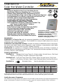
SolaStat-Eco.
Solar Hot Water Controller.
Features.
·Intelligent Heat Extraction From Solar Water Panels.
·High Quality, Efficiency, Reliability and +/-1C Accuracy.
·Stainless Steel, Water Resistant Temperature Sensors.
·Pre-wired with Mains Plugs and Sockets, no Electrician Required.
·Pre-Programmed to Customer’s Specification at No Extra Cost.
·All Values and Functions Installer Adjustable.
·Access Code Protected Front Panel Programming.
·Sensor Diagnostics and Smart Shutdown.
·Frost Protection Prevents Panels Freezing.
·Over Temperature Protection (Topout) for Ceramic Tap
and Ceramic Lined Hot Water Cylinders.
·Indication of SolaStat-Eco Status.
·Pump Timer for Pump Cavitation Recovery Option.
·Easy to Install with External Mounting Holes.
·Complies with Safety & EMC standards.
·Attractive Polycarbonate Enclosure.
·Enclosure and cables UV resistant.
·Water Resistant and Rear Cable Entry Options.
·1HP (750W) Relay Std, 2HP (1500W) Pool option.
Introduction.
SolaStat-Eco is Easy to Use with the advanced generation of smart, microprocessor based
Differential Solar Hot Water Controllers. The SolaStat-Eco is easy to install, easy to use, easy to
programme and visually appealing.
SolaStat-Eco has Advanced Functions and takes the basics of differential control, frost protec-
tion, topout and add to these sensor diagnostics, smart shutdown, comprehensive status lights
with the option of a Pump Timer for Pump Cavitation Recovery.
SolaStat Ltd has experience in designing and manufacturing Solar Hot Water Controllers to
Industrial Electronic Standards for over 15 years. This has earned SolaStat a reputation for Quality,
Accuracy, Efficiency and Reliability.
Ordering Information.
SolaStat-Eco Standard Unit: Pump Timer On, 4 Status Lights, 2m Inlet Sensor, 10m Panel
Sensor, 1 x 1hp Relay, 2m Mains Cable and Pump Outlet.
SolaStat-Eco-P Pool Unit: Pump Timer Off, 4 Status Lights, 2m Inlet Sensor, 10m Panel
Sensor, 1 x 2hp Relay, 2m Mains Cable, Pump Outlet and Water Resistant Enclosure.
SolaStat-Eco - Adjustable Value Specify adjustable values as required.
PT
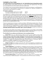
Quality Assurance Programme.
The modern technology and strict procedures of the ISO9001 Quality Assurance Programme applied during
design, development, production and final inspection grant the long term reliability of the instrument.
Z495
ISO9001
E
G
I
S
T
E
R
R
E
D
S
U
P
P
I
R
E
L
TECHNOLOGY
& QUALITY
A
W
A
R
D
19.03-3
.snoitpOgnignaRocE-tatSaloS
pmuP remiT TP elbatsujdA eulaV 1F 2F 3F 4F dradnatS ledoM
NOremiTT ffO/nOpmuPC2/C5C4/C8C5/C01C6/C21C6/C21
FFOremiT N tuOpoT FFO C06 C57 C59 C57
tsorFFFOC2C4C6C4
A dedicated swimming pool controller is available; SolaStat-Pool. It has a 2hp Relay and Pump Timer is Off..
High temperature silicon sensor cable, water resistant enclosure, and rear cable entry options are available.
SolaStat Models Include:
SolaStat-Eco: Controller c/w 4 Status Lights
SolaStat-Plus: Controller c/w Display.
SolaStat-Pool: Pool Controller c/w Display.
SolaStat-Rmt: Remote Display.
SolaStat-Rly: Slave Relay for HWC Control.
SolaData: PC Datalogging & Comms.

SolaStat-Eco Users Guide.
Your SolaStat-Eco has a microcomputer at its core that intelligently and automatically controls
your solar hot water system at greater efficiency. The SolaStat-Eco measures water temperatures
at 2 different places in the system and turns on a water pump at the optimum time. The pump
moves hot water from the solar collector into the hot water tank.
The SolaStat-Eco has advanced features that; protect the system from damage, run self diagnostics,
self correction of some problems and will keep you informed as to what the SolaStat-Eco is
measuring and what decisions it is making.
Principle of operation:
The solar hot water panel sensor is called ‘ROOF’
The lower hot water tank sensor is called ‘INLET’
The SolaStat-Eco is a differential solar hot water controller. The controller measures the temperature
at the ‘Roof’ sensor and compares this to the ‘Inlet’ sensor. If the difference between the roof and
the inlet is greater than the programmed upper limit (typically 12C) then the pump turns on and
transfers heated water from the solar collector to the tank and replaces this with cooler water from
the bottom of the tank. When this happens the tank heats up and the collector tends to cool down.
The heat difference is reduced to a point where the lower limit (typically 6C) is reached and the
pump turns off. This cycle repeats as long as the sun shines and there is a difference in temperature,
the tank heats up progressively this way.
There is a huge amount of energy in sunshine, as high as 1000 watts per square metre. This can
lead to water temperatures present in the hot water tank beyond what it is designed to handle
(close to boiling). This is especially true of ‘ceramic’ lined tanks. Also pressure can build which can
cause other plumbing problems. To protect the hot water tank and stop pressure problems a
maximum temperature can be set called ‘Topout’. This will prevent the pump from moving any
more water from the collector until the tank has cooled to a safe level.
To protect the solar collector from freezing in mild frost areas the ‘Frost’ function can be enabled.
This will turn the pump on to move a small amount of water through the collector. Heavy frost
areas may need other solutions such as glycol based systems or drain down.
The SolaStat-Eco has other special features to those mentioned above.
··
··
·Pump Timer: This is an optional factory setting to assist in pump cavitation recovery. After
the pump has run continuously for approximately ten minutes, it will turn off for one minute. This
cycle is repeated as long as the pump is required to run and will not affect normal operation in a
standard hot water collector and cylinder installation. The one minute turn off period helps any
accumulated air to escape from the pump and has been effective as a backup in exceptional
conditions. This feature can help prevent the pump running for hours in a ‘locked up’ state, in-
creasing the installation reliability. Also refer ‘Plumbing Issues, Cavitation’
NOTE: The Pump Timer is OFF in the SolaStat-Eco-P (Pool) version.
··
··
·20 DegC lockout: If the collector is less than 20C it will not contribute any useful heat, even
to cold water. Therefore the controller will not turn the pump on under differential conditions (‘frost’
protection still works).
··
··
·Sensor diagnostics: The SolaStat-Eco constantly checks the sensors. If the roof sensor is
above 140C, the pump is disabled. If a sensor is outside the specified temperature range of -40C
to 150C then the display flashes the ‘Topout’ light for the Roof sensor and flashes the ‘Frost’ light
for the Inlet sensor and the controller enters Smart Shutdown mode. The sensor has either a
slowly flashing light for a temperature above 150C (possibly shorted sensor or wire) or a fast
flashing light for a temperature below -40C (possibly open sensor or broken wire). For example if
the ‘Roof’ sensor wire is cut during some building work then the SolaStat-Eco ‘Topout’ light flashes
fast and the controller enters Smart Shutdown mode until the wire is repaired.
··
··
·Smart Shutdown (SSd): In Smart Shutdown mode, the ‘Topout’ and or ‘Frost’ light is flash-
ing and the pump is disabled except for ‘Frost’ protection when the Roof sensor is working.
19.03-4

··
··
·The ‘PWR’ light on indicates that power is being applied to the unit.
··
··
·The ‘PUMP’ light will be on when the pump is on. The exception to this is, if the Pump Timer
is on a one minute recovery cycle, the light will be on but the pump will not be running during that
minute. (see ‘Pump Timer’ explanation on previous page).
··
··
·‘TOPOUT’ light on indicates the value stored as the maximum allowable hot water tank
temperature has been reached. If lit the pump will be disabled until the temperature drops at least
2C lower.
··
··
·The ‘FROST’ light comes on when the value stored for the onset of a frost condition has
been detected on the solar collector. To stop the collector freezing and bursting, the pump will
come on just enough to raise the temperature of the collector by 2C. Only a small amount of warm
water is needed to protect the collector.
··
··
·The ‘PUMP’ button will turn the pump on as long as the button is held down, unless of course
the pump is already on in normal operation.
··
··
·The ‘TEST’ button will check the system during which all the lights should flash on.
··
··
·Pressing Button ‘F2’ flashes the Topout light and pressing Button ‘F3’ flashes the Frost light
but these buttons have no effect on unit operation.
SolaStat-Eco Users Guide, Cont.
·Pump override: For added flexibility you can make the pump operate manually. The pump
will turn on as long as the ‘Pump’ button is held down unless of course the pump is already on in
normal operation.
··
··
·Test: Briefly pressing this button will cause all the lights to flash for 3 seconds.
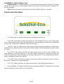
Display panel description.
19.03-5

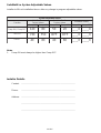
SolaStat-Eco System Adjustable Values.
Installer to fill in at installation time or after any change in program adjustable values.
Notes.
1. Pump ON must always be higher than Pump OFF.
Installer Details.
Contact: ................................................................................................
Phone: ................................................................................................
Address: ................................................................................................
................................................................................................
................................................................................................
19.03-6
seulaVelbatsujdAmetsyS
noitcnuF ocE-tatSaloS seulaVyrotcaF P-ocE-tatSaloS seulaVyrotcaF seulaVnoitallatsnI
NOpmuP FFOpmuP NOpmuP FFOpmuP NOpmuP FFOpmuP
FFOpmuP/NOpmuP
C21C6C5C2C____C____
TUOPOT
C37C57FFOFFOC____C____
TSORF
C4C6C4C6C____C____

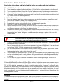
SolaStat-Eco Safety Instructions.
Read safety instructions and limit of liability before proceeding with the installation.
General Safety Instructions.
1. This installation guide is for the installation of SolaStat-Eco solar hot water controllers only
and is not an installation guide for any other part.
2. The complete installation should be checked at least annually for damage or malfunction.
3. All servicing to be carried out by an authorised service agent only.
4. All aspects of the installation must comply with local electrical and plumbing regulations (and
any special solar hot water regulations).
Installation Precautions.
1. Must be installed away from water sources such as rain, leaking pipes, or wet floors and
must not be installed in damp areas like bathrooms.
2. Must be installed away from direct sunlight, flammable liquids or radiant heat sources.
3. Power leads must be facing directly down, not sideways or upwards.
4. Must be in a safe environment for users to inspect.
5. Failure to mount sensors correctly can lead to a poorly controlled solar hot water system with
safety issues like overheating and over pressure damage to the plumbing and hot water tank
and freezing damage to the solar hot water collector.
6. Alteration of installer level program values outside those recommended values by SolaStat
and other parts suppliers (especially hot water tank manufacturer’s maximum recommended
temperature) can lead to dangerous conditions and/ or damage to parts of the solar hot
water system.
Electrical Precautions.
1. All mains voltage electrical work to be carried out by a qualified electrician, especially external
power outlet socket installation.
2. A readily accessible disconnect device, overcurrent device and RCD Protection rated to suit
the size of the pump plus 5VA must be incorporated in the power supply wiring. The overcurrent
device for a 1500W, 240Vac pump must not exceed 10Amps.
3. It is recommended that sensor leads be kept 300mm away from mains and comms cables.
4. Do not use mains power extension cords unless approved by the manufacturer.
Water resistant plugs and sockets should be used.
5. The SolaStat-Eco controlled outputs (PUMP) are connected to the input power supply wiring
and are not isolated from it. Supply voltages will be output through that outlet during activation.
6. Always use within specified voltage and load ranges. Never use with damaged leads, plugs
or sockets.
7. Do not allow the sensor cables to come within 10mm of the high voltage connectors or
components inside the enclosure.
Note on Hot Water Cylinders with Over Temperature Cutout.
Some standard electric element hot water tanks have an overtemperature cutout fitted to remove
power in the event of a thermostat failure. The temperature this is set to can typically range from
75C to 95C which is adequate for electric element heating safety. However in solar hot water
systems this temperature can be exceeded and the overtemperature cutout may activate turning
the electric element off. The cutout needs to be manually reset by a qualified electrician. In these
installations it may be necessary to modify the electrics in a manner approved by the hot water
tank manufacturer or set the topout adjustable value to a temperature lower than the
overtemperature cutout.
CAUTION: Dangerous Voltages may be present. The SolaStat has no user serviceable parts.
Protective enclosure only to be opened by qualified personnel.
Remove ALL power sources before removing protective cover.
19.03-7
Warning:
These products are not designed for use in, and should not be used for patient connected applica-
tions. In any critical installation an independent fail-safe back-up system must always be imple-
mented.

SolaStat-Eco Mounting.
Where to mount the SolaStat-Eco.
1. Against a flat vertical surface with sufficient strength to hold the enclosure and any additional
weight from the plugs, sockets and cables.
2. Power leads must be facing directly down, not sideways or up.
3. Safe for users to inspect.
4. The buttons can be easily read and accessed.
5. Allow for cable runs, location of power outlets and lengths of wires.
Mounting the SolaStat-Eco.
1. There is no need to open the enclosure during a standard installation.
2. Allow for the enclosure dropping 5mm from screw centres once mounted (keyhole mounting
system).
3. Place drill guide template against wall, checking for level alignment. 4 screws are supplied, 2
are chip board screws and 2 are combination Gib/ wood screws. It is recommended that all
4 mounting holes are used with at least 2 firmly secured into wood. The outer plastic Gib
anchors will self tap into Gib board and their inner metal screws fix into the centre of the
plastic anchors.
4. Mark and drill/ screw as appropriate leaving the heads of the screws above the surface by
approximately 3mm.
5. Place unit over the 4 screw heads, unit should slide down 5mm into the ‘key’ slots and
become secured to the wall. You will need to adjust screw height to obtain a secure fit.
Mounting the Sensors.
This is Critical to the Success of the Installation.
The sensors are the only way the SolaStat-Eco can efficiently control and protect the system.
1. The 10m ROOF Sensor.
The ‘ROOF’ sensor is best fitted into a metal immersion ‘pocket’ just inside the solar collector
in the hot water outlet pipe. Liberally apply heat transfer compound between the sensor and
the lining of the ‘pocket’. Sensor should be sealed with neutral cure sealant and externally
lagged, also the cable should be insulated from the bare pipe. Heat transfer compound is
available from your distributor or SolaStat ltd.
2. The 2m INLET Sensor.
If Topout is required; The ‘INLET’ sensor is best fitted into a metal immersion ‘pocket’ near
the middle of the hot water tank. Caution should be exercised to allow for stratification of hot
water in the tank. For Topout Adjustable Value we recommend a conservative value somewhat
lower than the hot water tank manufacturers maximum temperature. If Topout is not required
then the ‘INLET’ sensor is best fitted into a metal immersion ‘pocket’ near the bottom of the
hot water tank. Liberally apply heat transfer compound between the sensor and the lining of
the pocket’. If a ‘pocket’ is not available then bond the sensor against the metal wall of the
tank (not the outside cladding or insulation) using thermal transfer compound between the
tank and sensor.
Warning.
1. Removing or cutting the cladding may void hot water tank warrantee.
2. Sensors must not be immersed in water.
3. It is recommended that sensor leads be kept 300mm away from mains and comms cables.
4. Ensure the correct sensors are mounted in the correct place.
5. Failure to properly mount the ‘Inlet’ sensor as prescribed in the method above can result in;
a. The system may not operate at greatest efficiency.
b. There may be inaccurate ‘Topout’ sensing.HWC or other components may get damaged.
6. Failure to correctly mount the ‘Roof’ sensor as prescribed in the method above can result in;
a. The system may not operate at greatest efficiency.
b. Failure to detect Frost conditions. Panel can burst.
19.03-8

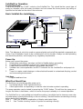
SolaStat-Eco Operation.
Connect the Pump.
Plug in the pump to the ‘PUMP’ socket on the SolaStat-Eco. This should be the correct type of
pump for domestic solar hot water circulation and not exceed the horse power (hp) rating as
specified on the label on the side of the enclosure.
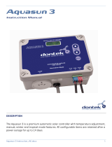
Basic SolaStat-Eco Installation.
19.03-9
Note. This diagram is only to be used as a general guide and not all the required components are
shown. Each installation needs to be customised to suit it’s situation. Always use best plumbing
and electrical practices, and comply to any regulatory requirements.
Power Up.
Before you connect the power;
1. Read safety instructions, warnings and limit of liability before proceeding.
2. Complete all the installation and securely mount the SolaStat-Eco.
3. Power outlet socket to be installed by a qualified electrician.
4. Suitable over-current protection and RCD Protection for the SolaStat-Eco and pump is in
place.
5. There is no water, metal shavings or other electrical hazards to contaminate the plug, socket
and surrounding environment.
Only then;
Plug it in and turn it on.
What You Should See.
The first thing you should see after power up is;
1. On the top left the ‘PWR’ light should be on.
2. Other lights will be on depending on how the solar hot water system is operating.
The pump operation can be tested by pressing the ‘PUMP’ button. This will turn the pump on as
long as the button is held down, unless of course the pump is already on in normal operation.
The SolaStat-Eco is now installed and should be working. It would be best to observe some solar
hot water pump cycles but this will rely on the sun shining. Check all functions are working correctly
before leaving the installation.
Note 1. See User Guide for explanation of display and status lights.
Note 2. See “Trouble shooting” section if system not working correctly.
.
.
INSULATION
COLD FLOW TO PANEL
HOT WATER OUT
DIFFERENTIAL CONTROLLER
INLET SENSOR
ROOF SENSOR
TEMPERATURE/PRESSURE
TEMPERING
VALVE
KEY: = WATER FLOW.
RELEASE VALVE
COLD WATER INLET
SOLAR COLLECTOR
COLD WATER IN
RECIRCULATING PUMP
HOT RETURN
NON-RETURN
VALVE
AIR
VENT
VALVE
FROM PANEL
INSULATION
PRE-WIRED
PLUG &
SOLASTAT-ECO
LEAD

SolaStat-Eco Sensor Maintenance.
Lengthening SolaStat-Eco Sensor Wire.
The sensor wire can be lengthened within certain guidelines. Poor connections or induced
interference can cause false temperature readings.
1. The sensor is not polarized- it can be connected either way around.
2. The wire normally used for sensor lengthening is twin 0.5mm^2 stranded speaker wire.
3. Firmly attach wires to each other by either soldering (heatshrink over each joint) or by quality
screw terminals. Joins must be kept dry.
4. It is recommended that sensor leads be kept 300mm away from mains and comms cables.
5. Over 20 metres; extra care must be taken to avoid electrical interference being picked up.
6. In ‘noisier’ electrical environments screened cable may be required.
7. The absolute maximum cable length is 100 metres.
Replacing a SolaStat-Eco Sensor.
If a damaged sensor needs to be replaced then the cover of the enclosure will need to be opened
unless the choice is made to join the wires externally (see “Sensor Wire Lengthening” section).
1. Remove the mains power supply, preferably remove the plug from the wall socket. Make
sure no other power source is feeding back through other connections.
2. Remove the 4 screw covers on each corner of the lid of the enclosure. This will require a fine
tipped tool such as a screw driver. Be careful not to damage the lid. Always press the tool
away from you to avoid injury if you slip.
3. Remove the 4 screws that hold the lid on.
4. Unscrew the damaged sensor from the terminal block.
5. Loosen the cable clamp for the sensor leads.
6. Carefully pull the wire back through the opening in the bottom case.
7. Thread the new sensor wire back through where the old one came from.
8. Place the wires of the new sensor into the terminal block where the old sensor came from
and retighten the screws.
9. Do not allow the sensor cables to come within 10mm of the high voltage connectors or
components inside the enclosure. Tighten the screws on the cable clamp.
10. Replace the lid, replace the 4 screws and tighten.
11. Push in 4 new screw covers available from your distributor or SolaStat Ltd. Note: there are
locating lugs to ensure correct orientation.
12. Reconnect the SolaStat-Eco and turn on the power.
13. Check sensor is reading correctly and check SolaStat-Eco operation as per “What You
Should See” section of this manual.
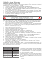
The table below has the correct resistance values of the sensor at different temperatures. The
sensor must be removed from the SolaStat-Eco to measure these values correctly. Follow the
above procedure for removal of the sensor.
CAUTION: Dangerous Voltages may be present. The SolaStat has no user serviceable parts.
Protective enclosure only to be opened by qualified personnel.
Remove ALL power sources before removing protective cover.
secnatsiseRrosneS erutarepmeT kniecnatsiseR WW
W
WW
C052.72
C52 00.01
C05261.4
C57 529.1
C001379.0
.'trohs'roC051evobA hsalFwolSthgiLrosneS 003.0<
.'nepo'roC04-woleB hsalFtsaFthgiLrosneS 002>
A short circuit can be caused by the sensor wires being
connected together. Check the wires are not partially
cut. (eg Sharp roofing iron.) or moisture is not getting
into the sensor causing corrosion.
An open circuit can be caused by the sensor wires being
broken. Check the wires are not cut. (eg Sharp roofing
iron.) or moisture is not getting into the sensor causing
corrosion.
19.03-10

1. The small yellow letters / words under the buttons now apply.
2. Enter the installer programming access code. Available from distributors.
3. All 4 lights will flash 4 times indicating you are in programming mode.
4. The ‘PUMP’ light will be flashing to indicate the adjustable value is the Pump ON / Pump
OFF value.
5. Select one of the adjustable values by pressing the corresponding button e.g. to
programme 12C ON / 6C OFF press button ‘F4’ and the F4 light will be on for a second.
6. Now the ‘TOPOUT’ light will be on to indicate the adjustable value is the ‘TOPOUT’
temperature. Wait for the light to change from steady on to flashing.
7. Select one of the adjustable values by pressing the corresponding button. (Selecting ‘F1’
will disable the ‘TOPOUT’ function and the F1 light will be on for a second).
8. Now the ‘FROST’ light will be on to indicate the adjustable value is the ‘FROST’
temperature. Wait for the light to change from steady on to flashing.
9. Select one of the adjustable values by pressing the corresponding button. (Selecting ‘F1’
will disable the ‘FROST’ function and the F1 light will be on for a second).
10. All the values have now been entered and will automatically be stored in permanent
memory.The unit will also store the values and exit if no key is pressed for a minute while
in programming mode.
11. Fill out the ‘System Adjustable Values’ in the user guide. (Page 6.)
SolaStat-Eco Programming.
If the adjustable values from the factory are inappropriate for the installation (see included document
stating programmed values) then the unit needs to be programmed.The programming access
code is for distributor or installer use only, as using incorrect adjustable values can cause
inefficiencies in the system or cause damage to the system voiding the warranty. Once new values
are ‘stored’ they are permanently written into memory and will be retained when power is removed
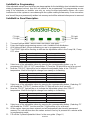
SolaStat-Eco Panel Description.
NOpmuP FFOpmuP
1FC5C2
2F C8 C4
3FC01C5
4F C21 C6
NOpmuP FFOpmuP
1FelbasiDelbasiD
2F C85 C06
3FC37C57
4F C39 C59
NOpmuP FFOpmuP
1FelbasiDelbasiD
2F C2 C4
3FC4C6
4F C6 C8
19.03-11
F1 Light
F2 Light F3 Light
F4 Light

Notes on SolaStat-Eco Programming
Note: Also refer Principle of Operation.
·Pump ON and Pump OFF.
Technically Pump ON and Pump OFF values are the ‘ROOF’ sensor temperature minus the ‘INLET’
sensor temperature and are called differential temperatures.
Example. Pump ON = 12C and Pump OFF = 6C.
When the solar collector has risen to 12C hotter than the HWC the pump turns on.
When the solar collector has fallen to 6C hotter than the HWC the pump turns off.
·In a high temperature system like domestic hot water relatively large Pump ON and Pump
OFF differentials like 12C Pump ON, 6C Pump OFF transfer hotter water over shorter periods of
time. Lower temperature systems like swimming pools or underfloor heating gain more energy
from the sun by transferring more water at lower temperatures and so have typical adjustable
values of 5C Pump ON and 2C Pump OFF.
·Increasing the ‘Pump ON’ value will let the solar collector heat up more before heat is
transferred to the tank. The advantage is hotter water entering the tank but may mean less operations
and lost energy on partly sunny days.
·Increasing the ‘Pump OFF’ value will mean the overall temperature of the water coming from
the solar collector is hotter on average when the pump turns off. This will help overcome heat
losses in pipes ensuring the water entering the hot water tank remains hotter than the water
already there but may result in less energy being transferred as above.
·The ‘FROST’ Adjustable Value is critical to avoid damage to solar collectors. The appropriate
value depends on installation variables such as geographic location, angle and type of solar collector,
sensor placement, fluid used, etc. All of these must be considered when determining the ‘FROST’
value. This is the installers’ responsibility. We recommend 4C as a minimum for the ‘FROST’
Adjustable Value in mild frost areas only but this may need to be increased for some installations.
·Topout is mainly needed for ceramic lined hot water tanks and other fittings and caution
should be exercised to allow for stratification of hot water in the tank. We recommend a conservative
value somewhat lower than the hot water tank manufacturers’ maximum temperature. It is vital the
sensor is mounted as recommend in the installation guide for topout to work correctly.
SolaStat-Eco Pump ON / Pump OFF Adjustable Range.
Note. Pump ON / Pump OFF; Four Ranges available:
Pump ON = 12C, Pump OFF = 6 C.
Pump ON = 10C, Pump OFF = 5 C.
Pump ON = 8C, Pump OFF = 4 C.
Pump ON = 5C, Pump OFF = 2 C.
19.03-12
Pump ON
Roof Sensor Solar Collector Temperature Pump ON
Roof Sensor Solar Collector Temperature Pump OFF
Inlet Sensor Cylinder or Pool Temperature
Temperature
Deg. Celsius Pump OFF

SolaStat-Eco Specifications.
Power Supply Voltage:
Supply Voltage. 230Vac ±10% (207~264Vac) 50/60Hz.
Max power usage. 2VA + external loads.
Relay Outputs. - Two Options can be ordered. (All ratings at 240Vac.)
-1. 1 x 1hp motor or 10A resistive.
-2. 1 x 2hp motor or 10A resistive.
Sensors.
Control range -40 ~ +150C
Stainless steel tip -40 ~ +150C; 6mm diameter x 30mm
PVC Sensor cable -40 ~ +105C; 4mm diameter, UV resistant. (Standard Units)
Silicon Sensor Cable -40 ~ +150C; 4mm diameter, UV resistant. (Special Order)
Accuracy +/-1C @ 25C
Adjustable Values Range (selectable in programming mode)
Pump-On/Pump-Off -4 ranges 12/6C, 10/5C, 8/4C, 5/2C
Top Out Protection -4 ranges 95C, 80C, 75C, disable.-2C hysteresis
Frost Protection -4 ranges 6C, 4C, 2C, disable +2C hysteresis
Custom Ranges available for larger quantities ordered.
EMC and Safety Compliances.
Emissions: EN 55022-A, CTick.
Immunity: EN 50082-1.
Safety Compliance: EN 60950, CTick.
General Specifications. (Unless otherwise stated in other input specifications.)
Operating Temperature: 0~60C
Operating Humidity: 90% RH Max. Non-Condensing
Enclosure Construction Polycarbonate - Impact Resistant
UL94 V-2 Non Burning, UV Stabilized
Water resistant or rear entry option available.
Dimensions L=167, W=142, H=40mm, excluding glands and cables
Weight. Standard model + sensors + packaging = 1200grams
19.03-13
Product Liability.
This information describes our products. It does not constitute guaranteed properties and is not
intended to affirm the suitability of a product for a particular application. Due to ongoing research
and development, designs, specifications, and documentation are subject to change without noti-
fication. Regrettably, omissions and exceptions cannot be completely ruled out. No liability will be
accepted for errors, omissions or amendments to this specification. Technical data are always
specified by their average values and are based on Standard Calibration Units at 25C, unless
otherwise specified. Each product is subject to the ‘Conditions of Sale’.

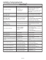
gnitoohSelbuorT
motpmyS esuaC noituloS
.sthgiloN,noitarepooN .rewopoN.a .tuonworbrewoP.b .degamaDtinU.c
.sesufkcehCroteltuosniamkcehC.a tuonworbelihwrewopevomeR.b .tneserpsinoitidnoc rewoper,setunim01rofrewopevomeR.c tinutonfI.gnitarepositinufieesdna .riapersdeen
dnagninnurtonpmup,NOthgilRWP .edistuoynnussitey .NOsithgilPMUP
.detcennocsidroytluafpmuP.a pmupdenrutsahremiTpmuP.b .ffo
.deggulpnuemocebsahpmupfieeS.a .tratserotpmuprofetunimenotiaW.b
dnagninnurtonpmup,NOthgilRWP .edistuoynnussitey .FFOsithgilPMUP .FFOsithgilTUOPOT
.ylreporpdetnuomtonrosneS.a .teyhguonetohtonretaW.b .C041revorosnesfooR.c
otdednobyllamrehtsirosneskcehC.a .teltuolenaPraloS ,telnIdnafooRfoserutarepmetkcehC.b ecnereffidehtnahtretaergebotdeenyeht .tiaW.NOpmuprofdemmargorp .delbasidpmuP,noitarepOlamroN.c
ynnussiteydnaetarepotonlliwpmuP .edistuo .FFOsithgilPMUP .NOsithgilTUOPOT
.dedeecxeerutarepmettuopoT.a tuopoTnahtretaergerutarepmetknaTfI.a gnikrowsinehteulavdemmargorp .yllamron
.ylsuounitnocgninnurpmuP
.gnitativacsipmuP.a .noitallatsnilaicepS.b .tcerrocnisgnitteS.c .kcolriA.d
senotsekilesiongnikamsipmupfI.a eeS.gnitativacsitinehttihguorhtgnissap .seussIgnibmulPtatSaloS nopmupgnolerehwnoitallatsnilaicepS.b .lamronerasemit .gnimmargorpkcehC.c .gninoitcnuf/dellatsnitonsevlavfeilerriA.d
.thgintasnurpmuP NOsithgilTSORF edistuotsorF.a .noitarepolamroN.a
.thgintasnurpmuP FFOsithgilTSORF esreversimetsyS.a .gninohpisomreht dettiftonsievlavnruter-nonehT.a .ytluafsiroyltcerroc
thginrevoyltnacifingisspordretaWtoH ybretawtohfoffowardonroelttiltey .resueht
esreversimetsyS.a .gninohpisomreht tsorfevissecxenanisimetsyS.b .aera .taehgnisolknaT.c
dettiftonsievlavnruter-nonehT.a .ytluafsiroyltcerroc htiwsnoitpoevitisnestsorfnonssucsiD.b .redivorp .knatretawtohnonoitalusnirettebllatsnI.c
tsaFgnihsalFthgiLTUOPOT .nekorbrosnesfooRoteriW.a .degamaDrosneSfooR.b .C04-wolebrosneSfooR.c
.eriwriapeR.a .rosneSfooRecalpeR.b .erutarepmeTedistuOkcehC.c
ylwolSgnihsalFthgiLTUOPOT .detrohsrosneSfooRoteriW.a .degamaDrosneSfooR.b .C051evobarosneSfooR.c
.eriWriapeR.a .rosneSfooRecalpeR.b .tiniretawsahrotcelloCkcehC.c
tsaFgnihsalFthgiLTSORF .nekorbrosnestelnIoteriW.a .degamaDrosneStelnI.b .eriwriapeR.a .rosneStelnIecalpeR.b
ylwolSgnihsalFthgiLTSORF .detrohsrosneStelnIoteriW.a .degamaDrosneStelnI.b .eriWriapeR.a .rosneStelnIecalpeR.b
SolaStat-Eco Trouble-shooting Guide.
This is intended as an initial guide to minimise service calls.
19.03-14

SolaStat-Eco Plumbing Issues.
Disclaimer.
For full information on compliance and safety standards for solar hot water systems the appropriate
local standards must be referred to. All plumbing to be carried out by qualified plumbers only.
We provide the following information as a guideline only to help obtain the greatest efficiency from
the system. Any information supplied here is based on feedback to us by experienced solar hot
water professionals and in no way represents a complete guide to plumbing such a system, as we
are not plumbers and do not represent ourselves as such. Best plumbing practices must be used
in all instances.
Introduction.
Any solar hot water system involves professional level plumbing and water much hotter than
would normally be seen in standard domestic hot water systems. For this reason SolaStat Ltd
recommends any installation is carried out by a registered and qualified plumber. All parts including
the pump must be rated for the elevated temperatures found in solar hot water systems.
Solar Hot Water Specifics.
1. Tempering valve.
There is a huge amount of energy radiated by the sun. It is not uncommon for the water from the
solar collector to exceed 100 C (under pressure).
Therefore it is vital a tempering or ‘mixing’ valve is fitted so the domestic supply from the tank does
not burn the end users. The tempering valve must be installed to best plumbing practices. The
tempering valve must be rated to handle these elevated temperatures.
2. Non return valve.
Hot water rises and cold water falls. If the solar collector is colder than the tank, such as during the
night, the hot water from the tank can self thermosiphon up to the collector. The collector now
radiates the heat to the cool night air and the water descends back down to the tank. To stop this
loss of hot water at night or during cloudy skies there has to be a one way or ‘non return’ valve
fitted.
The failure of this non return valve is a common problem with solar hot water systems. The orien-
tation of the valve as per manufacturer’s instructions is critical. Also the valve sometimes will not
close when swarf or other debris gets caught in the valve seat.
3. Pressure relief valves.
Solar hot water systems can run much hotter than standard domestic hot water systems. Hotter
water expands more and needs high quality pressure relief valves to avoid possible catastrophic
rupturing somewhere in the system, probably the tank.
Qualified plumbers using best industry practice must decide on adequate pressure relief valves,
the number and placement of them.
4. Air Relief Valves.
It is important that air relief valves are fitted (especially in a low pressure system) to the highest
point of both the feed to and the return from the solar water collectors. Otherwise air locks can
occur within the piping etc., and not just the pump. (An air lock in the system will increase the head
that the pump is working against and for some installations this is too much and the water ceases
to circulate. For systems where air locks occur, the pump may need to be set to a higher speed or
a higher head pump installed).
19.03-15

19.03-16
SolaStat-Eco Plumbing Issues, Cont.
5. Cavitation.
A pump is used to circulate the water between the tank and the collector.
If the pressure at the inlet or impellor of the pump falls below the vapour pressure of the liquid
being pumped, cavitation will occur. Cavitation in a pump is more likely to occur as the temperature
of the water rises and/or the pressure of the water decreases.
Bubbles form when the water is sucked into the pumps impellor and collapse again as small
implosions when the water is ejected out of the impellor which can be so rapid that a rumbling/
cracking noise is produced (it sounds like stones passing through the pump) and there can be
damage to the impellor and other sensitive components as well as a drop in water volume moved.
Mains pressure solar hot water systems are less susceptible to cavitation than low pressure systems
as the extra pressure will make it less likely that vapour bubbles will form.
As cavitation gets worse, less and less water is moved, often reaching a point where no water at all
moves. Since the solar hot water controller is still reading a ‘differential’ requiring water to flow
then the pump stays on until the vapour point drops. The vapour point drops either by water
pressure increasing or water temperature decreasing. When the pump is cavitating it may run
continuously for several hours.
To minimise cavitation;
1. Make sure the pump is appropriate for the installation.
2. If a variable speed pump then select the best setting (a slower speed that still has enough
head pressure is best as this will create the lowest pressure difference in the pump).
3. Mount the pump as low as is possible to achieve highest water pressure out of the tank
feeding into the pump.
4. Lower the resistance to water flow into the pump, such as less bends or more gradual
bends, or wider diameter pipes. Recommended minimum diameter pipe 1/2”.
5. In exceptional cases a larger pump with a larger impellor may need to be fitted to reduce
vacuum at the impellor.
6. Convert the system to mains pressure.
The SolaStat-Eco controllers have an optional factory setting called ‘Pump Timer’ to assist in
pump cavitation recovery. After the pump has run continuously for approximately ten minutes, it
will turn off for one minute. This cycle is repeated as long as the pump is required to run and will
not affect normal operation in a standard hot water collector and cylinder installation. The one
minute turn off period helps any accumulated air to escape from the pump and has been effective
as a backup in exceptional conditions. This should not be considered a substitute for the afore
mentioned best plumbing practices. This feature can help prevent the pump running for hours in a
‘locked up’ state, increasing the installation reliability.
NOTE: The Pump Timer is OFF in the SolaStat-Eco-P (Pool) version.
SS-Eco installation 190207.p65
SolaStat Distributor.
Email: [email protected]
-
 1
1
-
 2
2
-
 3
3
-
 4
4
-
 5
5
-
 6
6
-
 7
7
-
 8
8
-
 9
9
-
 10
10
-
 11
11
-
 12
12
-
 13
13
-
 14
14
-
 15
15
-
 16
16


Alpha Solar SolaStat-Eco Installation guide
- Category
- Water heaters & boilers
- Type
- Installation guide
Alpha Solar SolaStat-Eco is a high-quality, efficient, and reliable solar hot water controller.
Ask a question and I''ll find the answer in the document
Finding information in a document is now easier with AI
Other documents
-
 FAFCO Solar Bear User manual
-
 Dontek Aquasun 3 User manual
-
Pyle PLSLD5 Solar Pool Floats Light User manual
-
 Senztek Solastat 2-3 User manual
-
 Senztek solastat-1 User manual
-
WATERWARE TV252 Installation guide
-
 Advanced Solar Technologies Sunshine Solar Owner's manual
-
Full Gauge Microsol SWP Advanced User manual
-
Smartpool Sunheater Operating instructions
-
 ECO-WORTHY Solar Panel Roof Mounting System User manual


