Page is loading ...

Skuttle
®
Model 592-22
Power-Spray Humidifier
24-Volt
IMPORTANT:
THIS HUMIDIFIER MUST BE INSTALLED BY A QUALIFIED CONTRACTOR.
DO NOT INSTALL ON ANY SYSTEM WITH WATER PRESSURE
LESS THAN 40 P.S.I.
Installation on water systems with hardness ratings greater than 7 grains
is not recommended. Such installations can result in nozzle blockage,
dripping, erratic spray patterns and other maintenance problems.
Hardness above 7 grains will also produce dust from solids in the water
supply, which will be distributed throughout the home. Consult your
municipal water provider before continuing.
SAFETY PRECAUTIONS
READ THESE PRECAUTIONS AND ALL INSTALLATION INSTRUCTIONS
BEFORE INSTALLING THE HUMIDIFIER.
NOTE: Skuttle Mfg. Co. assumes no responsibility under warranty
if installer does not follow these instructions and safety precautions.
Do not install a humidifier where the heating temperatures can exceed 200°F.
Excessive temperatures will harm the humidifier, possibly causing water
damage to the home.
Do not install a humidifier where the surrounding temperature can be 32°F
or colder. Frozen water will damage the humidifier and burst the supply
pipe, resulting in home damage.
Do not cut or drill into any air conditioning or electrical accessories during
humidifier installation. DANGER: Electrocution is possible if you come
in contact with a live wire; blindness can occur if refrigerant contacts
your eyes.
When the humidifier is installed in an area where water damage could
occur, connect the humidifier’s overflow provision to a suitable drain pan.
For above-ceiling installations, always install a drain safety pan, plumbed to
a suitable drain.
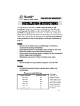
For initial recommended humidistat settings, refer to Table 1, below. (Be-
cause relative humidity affects people differently, these settings can be
raised or lowered slightly to suit personal comfort levels.)
CAUTION: Setting the humidistat higher than the recommended set-
ting can cause condensation, resulting in home damage. If excessive
moisture appears on windows or walls, reduce the humidistat’s humidity
setting enough to eliminate condensation. If the situation continues, turn off
the humidifier’s water source until condensation is gone.
Make sure the installation, wiring and plumbing of the humidifier comply
with local codes, ordinances and regulations.
INSTRUCTIONS
IMPORTANT: This product should not be used in conjunction with heat
pump systems. For heat pumps, select Skuttle Model 592-9, or upgrade to
Models 55UD, 86UD, or a 60-series steam humidifier.
GENERAL INFORMATION:
1.0 This humidifier puts moisture into the home by spraying a fine mist of water
into the warm air plenum, which is carried into the living area by the duct system.
1.1 When wired as recommended, the humidifier will operate only when the
furnace blower is in operation and the humidistat is calling for humidity.
1.2 The nozzle capacity (flow) is rated at 40 P.S.I. This capacity varies accord-
ing to line pressure, as shown in Table 2, below.
EXAMPLE: A home which requires .50 gallons of water per hour for proper humidifica-
tion, and which has a water pressure of 80 P.S.I., would need a .37 nozzle to do the job.
1.3 If the water pressure is excessive, a pressure regulator valve will be neces-
sary to obtain the proper volume of moisture.
REQUIRED TOOLS:
2.0 Aviation Snips • 1/4" Flathead Screwdriver • #1 Phillips Screwdriver •
Adjustable Wrench • Pliers • Electric Drill with 7/64", 1/4" and 3/8" Drill Bits •
Hammer • Center Punch
INSTALLATION INSTRUCTIONS
Outside
Temperature
Recommended
Setting
Outside
Temperature
Recommended
Setting
-20°F Low +10°F Med
-10°F Low +20°F High
0°F Med Above +20°F High
Table 1
Capacities in G.P.H. at Various Water Pressures
Nozzle Size
40 P.S.I. 60 P.S.I. 80 P.S.I. 100 P.S.I. 125 P.S.I.
.37 .37 G.P.H. .45 G.P.H. .55 G.P.H. .60 G.P.H. .70 G.P.H.
.50 .50 G.P.H. .60 G.P.H. .70 G.P.H. .80 H.P.H. .85 G.P.H.
.75 .75 G.P.H. .89 G.P.H. 1.10 G.P.H. 1.20 G.P.H. 1.40 G.P.H.
1.00 1.00 G.P.H. 1.20 G.P.H. 1.40 G.P.H. 1.60 G.P.H. 1.70 G.P.H.
1.50 1.50 G.P.H. 1.80 G.P.H. 2.10 G.P.H. 2.40 G.P.H. 2.70 G.P.H.
2.00 2.00 G.P.H. 2.50 G.P.H. 2.80 G.P.H. 3.20 G.P.H. 3.50 G.P.H.
Table 2
101 Margaret Street, Marietta, OH 45750
Phone: (800) 848-9786 • Fax: (740) 373-9565
Email: techservice@skuttle.com • Web: www.skuttle.com
GENERAL INFORMATION:
3.0 CAUTION: When selecting a location for the humidifier, make sure the
spray will not impinge or accumulate on any fan, limit controls, heating parts or
A-coils.
3.1 Select a location where the air will push the spray mist away from the
humidifier.
3.2 Mount the humidifier on the hot air
plenum only, with the nozzle pointing up in
the direction of airflow (see Figure 1, left).
On narrow plenums, mount the humidifier
on the narrow side.
3.3 If there is not enough room on the hot
air plenum, mount the humidifier further
downstream on the warm air duct, away
from the heating and cooling coil.
3.4 If it is necessary to mount the spray
nozzle further away from the humidifier (in
order to move the nozzle further into the
air stream for better absorption), remove
the nozzle adapter and 45° fitting from the
solenoid valve. Use the fittings supplied in
the parts bag to relocate the nozzle using
1/4" copper tubing (not supplied). (See
Figure 2, below, left.) CAUTION: Do not
allow copper tubing to come in contact
with sharp edges or surfaces that may
cause wear on the tubing.
3.5 Tape the template
(provided) on the warm air
plenum in the location
selected for the humidifier.
CAUTION: Make sure the
template is level.
3.6 Center punch and drill
four 7/64" mounting holes,
as shown on the template.
DANGER: Make sure you
are not cutting or drilling in-
to air conditioning or elec-
trical accessories.
3.7 Drill a 3/8" hole in the
center portion of the tem-
plate and cut a rectangular
opening, as instructed on
the template.
3.8 Install the drain cup
over the nozzle; attach it
with a #6 x 3/8" sheet
metal screw. (See Figure
3, left.)
3.9 Install 3/16" I.D. tubing
on the copper humidifier
drain and run it to a waste
drain. (An occasional drip
from the drain tube when
the humidifier is operating
is normal.)
3.10 Attach the humidifier
with four #8 sheet metal
screws.
PLUMBING THE HUMIDIFIER:
4.0 Select the nearest cold water pipe and install the saddle connector and
needle valve, supplied with this unit. USE COPPER TUBING ONLY.
The needle valve is a self-piercing valve when installed on copper pipe.
Follow the instructions supplied with the valve.
Mount the valve so that water will come from the top or side. This will re-
duce the chance of minerals clogging the valve.
4.1 Follow these compression plumbing tips:
Lightly clean the tubing ends with fine sandpaper before making connec-
tions.
Make sure the tubing is fully inserted into the fitting before tightening the
compression nut.
4.3 IMPORTANT: After attaching the saddle valve, thoroughly flush the supply
tubing to clear the line. Otherwise, debris could block the water flow at the sole-
noid valve.
4.4 IMPORTANT: To assist you with cleaning, note the proper orientation of
parts for assembly and disassembly. (See Figure 4, on back.)
Part No. 0756-163
Rev. 7/03
BEGIN READING ON OPPOSITE PANEL
Continued on back...
Figure 1
Figure 2
Figure 3

4.5 Slide the hex nut over the copper tubing end. Slide the brass ferrule over the
tubing. Push the end of the tubing into the threaded fitting and slide the hex nut
up to the fitting. Tighten the nut.
4.6 Slide the bushing over the tubing, Insert the bushing through the humidifier
wall until it snaps into place.
4.7 Open the needle valve at the cold water pipe. IMPORTANT: Check all fit-
tings for leaks.
MOUNTING THE HUMIDISTAT:
5.0 NOTE: See the installation instructions packaged with the enclosed humidi-
stat (humidity controller).
5.1 NOTE: When wiring the unit to a system that has a multi-speed blower mo-
tor, or that uses a motor other than 120 VAC, include the Skuttle A50 Interface
Relay in your installation.
HUMIDIFIER CHECKOUT:
Check the humidifier operation by following these procedures:
6.0 Turn on the water valve to the humidifier.
6.1 Turn the humidistat to the “ON” position.
6.2 Set the furnace thermostat high enough to allow the furnace to come on.
When the furnace blower comes on, the humidifier should start spraying
(provided there is enough heat reaching the humidifier thermostat).
6.3 Check the humidifier operation by turning the humidistat off, making sure the
humidifier stops spraying. NOTE: If the humidifier continues spraying, there may
be an error in wiring. Review the wiring diagram, above.
6.4 Set the furnace thermostat low enough to allow the furnace to shut off. The
humidifier should stop spraying either before or as the furnace blower shuts off.
NOTE: Again, if the humidifier continues spraying, there may be an error in writ-
ing. Consult the wiring diagram.
6.5 If the humidifier shuts off correctly, repeat steps 6.2 through 6.4 at least five
times. Each time, check to see that no water impinges on ductwork or any part of
the heating system. NOTE: If water impingement or fallout could occur, YOU
MUST INSTALL A SUITABLE DRAIN PAN, PLUMBED WITH AN ADEQUATE
RUNOFF DRAIN.
6.6 Set the thermostat to the desired setting.
6.7 Finally, set the humidistat as recommended in Table 1, on the front of these
instructions.
HUMIDIFIER PARTS:
7.0 Parts may be ordered through your local heating or plumbing dealer. (See
Figure 6, below).
7.1 When ordering repair parts, always give the following information:
Model Number
Serial Number (if possible)
Part Number (See Table 3, right, top.)
Part Name
PARTS LIST
HOMEOWNER HUMIDIFIER TIPS:
8.0 If the mineral content of the water in your home is above normal, a lime dust
may form in the duct distribution system, as well as in your living areas.
8.1 In a home that has had little or no humidification, a new humidifier may op-
erate almost continuously to attain the desired level of relative humidity. This is
because furniture, woodwork carpeting, plaster and houseplants will absorb the
newly-produced humidity to reach normal moisture levels. This period of adjust-
ment will take approximately three weeks.
8.2 Natural drafts in the home can cause humidified air to escape through open
fireplace dampers. Make sure they are closed when not in use.
8.3 When the weather turns warmer, humidification is unnecessary. IMPOR-
TANT: Turn the water and electrical power to your humidifier ‘OFF” after
each heating season.
8.4 When water frequently flows through your humidifier, the nozzle and/or sole-
noid valve can become clogged by lime and other mineral deposits, thereby di-
minishing humidification effectiveness. When this occurs, you should replace the
affected part(s). In fact, it’s a good idea to replace the spray nozzle at the start of
each heating season to help ensure continuous, trouble-free operation of your
humidifier. (You may wish to have your heating or plumbing contractor perform
this service for you.)
8.5 The inline water filter should be cleaned at the end or beginning of each
heating season. To do so, loosen the hex nut (see Figure 4, left, top), slide the
tubing out of the tube connector and remove the filter. At this time, the solenoid
valve may be disassembled for cleaning.
8.6 IMPORTANT: For parts and service, contact your local authorized dealer.
CAUTION: If excessive moisture appears on windows or walls, reduce the
humidity setting on your humidistat enough to eliminate condensation. If the
situation continues, turn off the water valve that permits water flow to the humidi-
fier, and contact your heating or plumbing contractor.
Key No. Part No. Description Qty.
1 000-1715-013 Mounting Panel 1
2 A00-0641-099 Front Panel Assembly 1
3 000-0431-019 Thermostat 1
4 A00-1319-034 Drain Basin Assembly 1
5 000-0814-070 Indicator Light, 24-Volt 1
6 000-1106-018
(Part no. varies w/size)
.50 Gal. Nozzle
(Consult whlslr. for available sizes)
1
7 000-1319-055 Nozzle Body 1
8 000-1319-054 45° Street Elbow 1
9 A01-0814-148 Solenoid Valve, 24-Volt
(includes Key Nos. 10 & 12)
1
10 000-1319-070 90° Street Elbow 1
11 000-1154-000 Tubing Connector 1
12 000-1319-051 Inline Filter 1
13 A00-1128-005 Self-Piercing Valve 1
14 SK0-0055-001 Humidistat 24-Volt Wall or Duct
Mounting
1
Table 3
NOTES
Wiring Diagram / Figure 5
Figure 4
Figure 6
/