Page is loading ...

Instrucciones en español adentro / Instructions en français à l’intérieur
61-547 AC/DC Voltage Indicator
IDEAL
®
Test and Measurement

Notes

Introduction .......................................................................4
Contacting IDEAL INDUSTRIES, INC ..........................................4
Safety Information ...............................................................5
Warnings ................................................................................................... 5-6
Cautions ........................................................................................................ 6
Symbols ........................................................................................................7
Operation......................................................................8-11
Identification and description of operating controls and functions ........... 8-9
Operating Features ......................................................................................10
Using Test Leads ......................................................................................... 10
Meter Operation .........................................................................................11
Measuring Voltage ......................................................................................11
Functions Operation Table ........................................................................... 12
Electrical Specifications ..............................................................................13
Environmental Specifications ................................................ 13
Mechanical Specifications ................................................... 14
EMC / EMI ....................................................................... 14
FCC ............................................................................ 14
Safety ............................................................................ 14
Maintenance and Service .................................................... 15
Table of Contents
3

Introduction
The IDEAL 61-547 AC/DC Voltage Indicator is an auto indicating tester that
indicates the voltage level in predetermined steps via integral leads. It auto selects
AC or DC voltage from 24 to 600 AC and 12 to 600 DC and also indicates DC
polarity.
Contacting IDEAL INDUSTRIES, INC.
To contact IDEAL INDUSTRIES, INC., call one of the following telephone numbers:
IDEAL Industries USA Customer Service
• Phone Number: 800-435-0705
• Email: [email protected]
IDEAL Industries Canada Customer Service
• Phone Number: 905-683-3400
• Email: [email protected]
IDEAL Industries EMEA
• Phone Number: +44 (0)1925 444 446
• Email: eur[email protected]
IDEAL Industries Australia
• Phone Number: +61 3 9562 0175
• Email: [email protected]
Or visit the IDEAL Electrical Website at www.idealind.com
To register your product, find manuals, watch videos, simply scan this QR code.
4
Arc Flash and Shock Hazard, Proper PPE Required. Follow all safety procedures,
wear proper PPE in accordance to NFPA 70E. Read and fully understand the
instruction manual prior to using this product. Failure to comply can result in
serious injury or death.

To contact IDEAL INDUSTRIES, INC., call one of the following telephone numbers:
IDEAL Industries USA Customer Service
• Phone Number: 800-435-0705
• Email: [email protected]
IDEAL Industries Canada Customer Service
• Phone Number: 905-683-3400
• Email: [email protected]
IDEAL Industries EMEA
• Phone Number: +44 (0)1925 444 446
• Email: eur[email protected]
IDEAL Industries Australia
• Phone Number: +61 3 9562 0175
• Email: [email protected]
Or visit the IDEAL Electrical Website at www.idealind.com
To register your product, find manuals, watch videos, simply scan this QR code.
Warning - Identifies conditions and actions that could result in
possible death or serious injury if the hazard is realized.
Caution - Identifies conditions and actions that could result in meter damage,
equipment under test damage or data loss if the hazard is realized.
WARNING
Safety Information
Arc Flash and Shock Hazard, Proper PPE Required. Follow all safety procedures,
wear proper PPE in accordance to NFPA 70E and follow the guidelines below and the
instructions in this manual when operating the meter. Failure to comply can result in
serious injury or death.
• Choking Hazard, Small Parts. Keep Away from Children. Sharp
Objects Hazard, This is not a toy. It is not for use or play by children. Keep
Away from Children. Failure to do so can result in serious injury.
• Only experienced or technically competent consumers should use this
equipment. When in doubt, call an experienced electrician to make any and
all necessary repairs or installations. At all times, perform any necessary
work on a de-energized circuit that has had its circuit breaker turned off and
has been locked out.
• Use the Meter only as specified in this manual or protection provided by the
Meter can be compromised.
• Before using or connecting the Meter, visually inspect it to ensure the cases
are not cracked and the back case is securely in place. Do not use if the
Meter appears damaged.
• Before using the test leads, inspect carefully for damaged insulation,
exposed metal or cracked probes. Check test leads for continuity. Do not use
leads if they appear damaged.
• Use only approved test leads. Do not use improvised connections that could
present a safety hazard.
• When using the probes, keep fingers behind the finger guards on the
probes.
• Connect the common test lead before connecting the live test lead. When
disconnecting test leads, disconnect the live test lead first.
• This Meter is intended for use by qualified electricians. Follow NFPA 70E
Standards for Electrical Safety in the Workplace when using this Meter.
• Do not use Meter if it operates incorrectly as protection may be
compromised. When in doubt, have the Meter serviced.
• When servicing the Meter, use only specified replacement parts.
5

Arc Flash and Shock Hazard, Proper PPE Required. Follow all safety procedures,
wear proper PPE in accordance to NFPA 70E and follow the guidelines below and
the instructions in this manual when operating the meter. Failure to comply can
result in serious injury or death.
• Have the Meter serviced only by qualified service personnel.
• Do not use the Meter around explosive gas, dust, or vapor, or during
electrical storms, or in wet environments.
• When measuring, keep fingers behind the Tactile Barrier. See “The
Meter” on pg. 8 and 9.
• Do not apply more than the rated voltage, as marked on the Meter,
between the terminals or between any terminal and earth ground.
• Voltages exceeding 30VAC or 60VDC pose a shock hazard so use
caution.
• Always ensure that test leads are secured so that they cannot be
accidentally snagged or tripped over.
• Do not work alone so that assistance can be rendered in an emergency.
• Use extreme caution when working around bare conductors or bus bars.
Contact with the conductor could result in electric shock.
• Adhere to local and national safety codes. Individual protective
equipment must be used to prevent shock and arc blast injury where
hazardous live conductors are exposed.
• These meters are IP42 dust & water resistant. Following any contact with
water, thoroughly dry meter and test leads prior to subsequent use.
• Cancer and Reproductive Harm - www.P65Warnings.ca.gov
6
Meter damage, equipment under test damage or data loss can occur
if the following guidelines are not adhered to.
• Use the proper terminals, function, and range for the measurement
application.
• Clean the case and accessories with a damp cloth and mild detergents only.
Do not use abrasives or solvents. Make sure the meter is completely dry
before use.
CAUTION
WARNING

Symbols & Descriptions
NOTE: The Measurement Category (CAT) and voltage rating of any combination
of test probe, test probe accessory, current clamp accessory, and the Meter is the
LOWEST rating of any individual component.
SYMBOL DESCRIPTION
Arc Flash and Shock Hazard
Shock Hazard
Warning or Caution
Choking Hazard
AC (Alternating Current)
DC (Direct Current)
Earth Ground
CAT III
IEC Measurement Category III
CAT III has protection against transients in equipment in fixed-
equipment installations such as distribution panels feeders,
and short branch circuits. Also included are lighting systems in
larger buildings.
V
Voltage AC or DC
Double Insulation
Do not dispose of this product as unsorted municipal waste.
It must be properly disposed of in accordance with local
regulations. Please see www.epa.gov or www.erecycle.org for
additional information.
Conforms to applicable North American Safety Standards
Conforms to applicable Australian Safety Standards
Conforms to European Directives
7

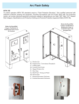
Identification and Description of Operating
Functions for the 61-547 AC/DC Voltage Indicator:
1. DC Volts Level Indication
2. Tactile Barrier
3. DC Volts Polarity Indication
4. Probe Holders
5. Integral 18-inch Test Leads
6. Ergonomic Non-Slip Grip
7. AC Volts Indication
8. PPE Level Marker
9. AC Volts Levels Indication
10. Hanging Strap Clip
8
Operation

1. DC Volts Level Indication
2. Tactile Barrier
3. DC Volts Polarity Indication
4. Probe Holders
5. Integral 18-inch Test Leads
6. Ergonomic Non-Slip Grip
7. AC Volts Indication
8. PPE Level Marker
9. AC Volts Levels Indication
10. Hanging Strap Clip
5
1
4
9
3
6
9
2
7
8
10

High Voltage Warning (HI-V)
The meter indicates PPE by showing a PPE warning on the meter face. When
measuring >36V AC on the VAC function and >36V DC when on the VDC function.
10
Operating Features
Using Test Leads
WARNING: Arc Flash and Shock Hazard, Proper PPE Required.
Follow all safety procedures, wear proper PPE in accordance to NFPA 70E and
follow the guidelines below and the instructions in this manual when operating
the meter with the integral test leads. Test Leads must be rated for the electrical
environment the meter is being used in and have a voltage rating of at least the
voltage of the circuit to be measured. Failure to comply can result in serious injury
or death.
• Choking Hazard, Small Parts. Keep Away from Children. Sharp
Objects Hazard, This is not a toy. It is not for use or play by children. Keep
Away from Children. Failure to do so can result in serious injury.
• These meters are IP42 dust & water resistant. Following any contact with
water, thoroughly dry meter and test leads prior to subsequent use.
WARNING:
1. Use only approved test leads. Do not use improvised connections that could
present a safety hazard.
2. Prior to using the test leads, inspect them carefully for damaged insulation,
exposed metal or bent probes. Check test leads for continuity. Do not use
leads if they appear damaged.
3. When using the probes, keep fingers behind the finger guards on the
probes.
4. Connect the common test lead before connecting the live test lead. When
disconnecting test leads, disconnect the live test lead first.
5. Always ensure that test leads are secured so that they cannot be accidentally
snagged or tripped over.
This meter has integral test leads. They are not replacable.The lead set must comply
with requirements for Overvoltage and Measurement Categories CAT III 600V.

11
Meter Operation
Measuring AC ( ) or DC ( ) Voltage

Indication Response Default Function Operation
Illuminated
Light
ACV/DCV ACV
Auto selects AC or DC voltage
and indicates DC polarity.
Functions Operation Table
12
Functions Indication Table
Function Description
PPE Visual indication that you have exceeded 36 volts AC or DC
AC V
Indication
Visual confirmation of the detection of AC voltage
DC V
Indication
Visual confirmation of the detection of DC voltage
DC Polarity DC polarity indication via “+” or “-”

Indication Response Default Function Operation
Illuminated
Light
ACV/DCV ACV
Auto selects AC or DC voltage
and indicates DC polarity.
Function Description
PPE Visual indication that you have exceeded 36 volts AC or DC
AC V
Indication
Visual confirmation of the detection of AC voltage
DC V
Indication
Visual confirmation of the detection of DC voltage
DC Polarity DC polarity indication via “+” or “-”
Electrical Specifications
Function Range Steps Accuracy
61-547 ±(a%+b)
AC Voltage (V) 24-600V
24, 48, 120, 208, 240,
277, 480, 600 steps
N/A
DC Voltage (V) 12-600V
12, 24, 36, 48, 110,
220, 380, 600 steps
N/A
1. Overload Protection: 600VRMS AC/DC.
2. Voltage level indication is approximate. We recommend using a digital
multimeter if a precise reading is required.
13
Environmental Specifications
Operating Temperature: 32ºF to 104ºF (0ºC to 40ºC) (<80%RH)
Operating Altitude: 6500 ft (2000 m)
Storage Temperature: 14ºF to 122ºF (-10ºC to 50ºC) (<80%RH)
Intended for indoor use.

14
Mechanical Specifications
Dimensions: (L x W x H) 6.12 in. x 2 in. x 1.7 in.
(155.5 mm. x 50 mm. x 42 mm.)
Weight: 0.29 LBS (0.13 KG)
Display: 8 Segment LEDs
Power Source: No Batteries Required
Ingress Protection Rating: IP42 dust and water resistant
EMC/EMI
CISPR 22 3rd Edition. Class B Limits.
EN 55032
CISPR 32
CISPR 11
FCC 15. 107 with reference to Section 15.109 (g).
ICES-003
EN 61326-2-2 Sec 6.4.2.101
USA (FCC)
47 CFR 15 subpart B. This product is considered an exempt device per
clause 15.103.
Safety
Complies with the following:
IEC 61010-1, Edition 3 (2010-06) +AMD1 (2016-12)
ANSI/UL/IEC EN 61010-1, Edition 3 (2016-04-29)
CSA-C22.2 No. 61010-1-12 Edition 3 (2019-07-19)
IEC 61010-031 Hand-held Probe Assemblies (2015-05)+AMD1(2018-05)
IEC 61010-2-033 (2019-06)
UL1436
Overvoltage CAT III 600V.
Any voltages exceeding the defined maximum voltage measurement categories
described above are outside the normal use of the equipment and protection cannot
be guaranteed.
Pollution Degree Class 2

Mechanical Specifications
Dimensions: (L x W x H) 6.12 in. x 2 in. x 1.7 in.
(155.5 mm. x 50 mm. x 42 mm.)
Weight: 0.29 LBS (0.13 KG)
Display: 8 Segment LEDs
Power Source: No Batteries Required
Ingress Protection Rating: IP42 dust and water resistant
EMC/EMI
CISPR 22 3rd Edition. Class B Limits.
EN 55032
CISPR 32
CISPR 11
FCC 15. 107 with reference to Section 15.109 (g).
ICES-003
EN 61326-2-2 Sec 6.4.2.101
USA (FCC)
Safety
15
Equipment Maintenance and Service
Meter Inspection
Do not use if meter appears damaged. Visually inspect the meter to ensure case and
jaws are not cracked.
Test Lead Inspection
Inspect and replace test leads if insulation is damaged, metal is exposed, or probes
are cracked. Pay particular attention to the insulation surrounding the connectors.
Battery Inspection/Replacement
This unit uses no batteries.
Maintenance and Storage
Switch off and disconnect the meter completely before carrying out any
maintenance. Clean the case with a damp cloth and mild detergent. Do not use
abrasives or solvents. Keep away from liquids and ensure the meter is completely
dry before use.
Service and Replacement Parts
This unit has no user-serviceable parts.
Probe Storage
Maintenance and Service

In order to preserve, protect and improve the quality of the environment, protect
human health and utilize natural resources prudently and rationally, the user
should return unserviceable product to relevant facilities in accordance with
statutory regulations. The crossed-out wheeled bin indicates the product needs to
be disposed separately and not as municipal waste.
Do not dispose of this product as unsorted municipal waste. It must be properly
disposed of in accordance with local regulations. Please see www.epa.gov or
www.erecycle.org for additional information.
There are no batteries in this product.
Disposal of Waste, Electrical & Electronic Equipment
Disposal of Used Batteries/Accumulators
TWO YEAR LIMITED WARRANTY
This tester is warranted to the original purchaser against defects in material and
workmanship for a period of two (2) years from date of purchase. With proof of
purchase from an authorized IDEAL distributor, a defective tester will be repaired or
replaced with the same product or a functionally equivalent product, at the option
of IDEAL INDUSTRIES, INC. during the warranty period, subject to verification
of the defect or malfunction. Warranty does not cover consumables such as
fuses, batteries, and excludes defects caused by leakage from batteries, abuse,
mishandling, dropping, ordinary wear and tear, misuse, neglect, unauthorized
repair, improper use, alterations, accidents or any causes beyond IDEAL’s
reasonable control. Consequential or incidental damages are not recoverable under
this warranty. Some states do not allow the exclusion or limitation of incidental or
consequential damages, so the above limitation or exclusion may not apply to you.
This LIMITED WARRANTY gives you specific legal rights, which vary from state to
state. This warranty constitutes the sole and exclusive remedy of the purchaser and
the exclusive liability of IDEAL, and is in lieu of any and all other warranties, and
expressly disclaims all other warranties, implied, or statutory as to merchantability,
fitness for purpose sold, description, quality productiveness, or any other matter.
No agent, distributor or other supplier has the authority to modify or amend this
warranty or make other representations or warranties other than those contained
in this warranty without express written authorization from IDEAL. For warranty
service, call IDEAL customer service at 1-800-435-0705.
Made in China.
16

Disposal of Waste, Electrical & Electronic Equipment
Disposal of Used Batteries/Accumulators
Scan the barcode on the right to see the new IDEAL T&M Product Line
IDEAL INDUSTRIES, INC. Sycamore, IL 60178, U.S.A. 800-435-0705 www.Idealind.com ND 9022-2

Instrucciones en español adentro / Instructions en français à l’intérieur
61-547 Indicador de Voltaje CA/CD
IDEAL
®
Prueba y Medición

Notes

Introducción .................................................................... 21
Cómo contactar a IDEAL INDUSTRIES, INC. ............................... 21
Información de Seguridad ................................................... 22
Advertencias .......................................................................................... 22-23
Precauciones ...............................................................................................23
Símbolos ..................................................................................................... 24
Operación ................................................................... 25-28
Identificación y descripción de controles de operación y funciones ................. 25-26
Funciones de Operación ..............................................................................27
Uso de los Cables de Prueba ......................................................................27
Operación del Medidor ................................................................................28
Medición de Voltaje ....................................................................................28
Tabla de Operaciones de Funciones ............................................................29
Especificaciones Eléctricas ..........................................................................30
Especificaciones Ambientales ............................................... 30
Especificaciones Mecánicas ................................................. 31
EMC/EMI......................................................................... 31
FCC ............................................................................ 31
Seguridad ....................................................................... 31
Mantenimiento y Servicio .................................................... 32
\
Índice
20
/