Page is loading ...

A.E.B. INDUSTRIALE s.r.l.
Via Brodolini, 8 - 40056 Crespellano (Bo) - ITALIA
Tel. + 39 051 969870 - Fax. + 39 051 969725
Internet: www.dbtechnologies.com
E-mail: [email protected]
Digital Vertical ArrayDigital Vertical Array
T
MANUALE d’USO - Sezione 1
USER MANUAL - Section 1
BEDIENUNGSANLEITUNG - Abschnitt 1
CARACTERISTIQUES TECHNIQUES - Section 1
Made in Italy
COD. 420120184 Rev 3.0

CLASSIFICAZIONE EMI
In accordo alle normative EN 55103, l'apparato è progettato e idoneo all'utilizzo in ambienti
Elettromagnetici E3 o inferiori (E2, E1).
DATI TECNICI
Sistema Attivo 3-Amps
Tipologia amplificatore Digitale - Classe D
Tecnologia DIGIPRO G2
Potenza RMS 1410W
Alti (HF) RMS 350W
Medi (MF) RMS 350W
Bassi (LF) RMS 710W
Potenza musicale 2820W
Risposta in frequenza (-6dB) 60-19.000Hz
Crossover MF-HF (Medi-Alti) 1900Hz
24dB/Oct
Crossover LF-MF (Bassi -Medi) 420Hz
24dB/Oct
Pressione sonora (SPL) 136dB max
Componenti 1 woofer 12" - VC 3" - Neodimio
2 midrange 6,5" - VC 2" - Neodimio
3 compression driver 1" - VC 1.5" - Neodimio
Sensibilità ingresso nominale 0dBu
Impedenza ingresso
Bilanciato 20Kohm
Sbilanciato 10Kohm
Alimentazione Full-range con PFC e SMPS
100-240V~ 50-60Hz
Corrente di accensione 14,9A
Dimensioni (LxHxP) 580x386x430mm
Peso 29,9Kg
PROCESSORE DSP
DSP Analog Device 56 bits
Conversione audio 24 bit / 96kHz S/N=116dB
Controllo volume Digitale
Equalizzazione 9 preset EQU
MECCANICA
Materiale box Polipropilene (PP)
Rinforzi interni box Alluminio
Materiale staffe appendibilità Acciaio
Angolazioni staffe 0° - 1,5° - 3° - 4,5° - 6° - 8° - 10°
Forma del diffusore Trapeziodale - angolazione 10°
Maniglia 1 x lato
Rete frontale Lamiera forata 1.2mm con foam interno.
ItalianoItalianoItaliano
Manuale d’usoManuale d’uso
7
DESCRIPTION
The DVA T12 is equipped with three class D amplifiers of DIGIPRO® G2 series, high efficiency,
which delivers high output power in a compact size and low weight. Thanks to its high
efficiency the cooling of the amplifier module is obtained statically, thus avoiding the use of a
fan.
®
The power supply circuits of the DIGIPRO G2 amplifier has been conceived to work in full-
range mode; thanks to the SMPS (Switched-Mode Power Supplies) technology with PFC
(Power Factor Correction) the operation with supply voltages between 100 Vac and 240Vac is
guaranteed by ensuring the same sound performances even with floating and non-stabilized
power supply systems.
The amplifier module is able to deliver 710W (RMS) for the bass section, 350W (RMS) for the
mid-section and 350W (RMS) for the treble section.
The bass section controls a 12" neodymium
woofer (3" voice coil) in a band-pass
configuration enclosed inclined inside the
box. This configuration guarantees a high
SPL and the obtainment of frequencies of up
to 60Hz.
The mid-section controls two 6.5"
neodymium midranges (2" voice coil),
enclosed in their own acoustic chamber and
horn loaded with a power factor corrector.
The plug phases located in front of the cones
prevent the vertical phases from overlapping,
creating in fact a local array with 6 output slot
that increases directivity. The horn design
was specifically created to couple it correctly
with the DVA T4 modules.
The treble section controls three 1"
neodymium drivers (1.5" voice coil)
positioned vertically on an aluminum support
and spaced to optimize the vertical cover.
The horn design was specifically created to
couple it correctly with the DVA T4 modules.
EnglishEnglishEnglish
user manualuser manual
8

EnglishEnglishEnglish
user manualuser manual
10
user manualuser manual
EnglishEnglishEnglish
9
This specific design has made it possible to obtain a constant and precise 100° coverage in a
horizontal direction and 10° coverage in a vertical director for each diffuser.
CONTROLS AND FUNCTIONS
"Balanced Audio" section
1) " INPUT” INPUT CONNECTOR
Balanced input at line level. It is able to accept “XLR” sockets.
2) "LINK” OUTPUT CONNECTOR
The “XLR” connector connected in parallel with input (1) can be used to send the input
audio signal to another amplified speaker.
"Status" section
3) “LIMITER” INDICATOR LIGHT
This indicator comes on red to indicate that the internal limiter circuit has tripped.
This prevents amplifier distortion and protects the speakers against overloads.
Always avoid operating conditions where the system works for long periods of
time with LED flashes or it is always ON
4) “SIGNAL” INDICATOR LIGHT
This indicator comes on green to indicate the presence of an input signal to a level
higher than-20dBu.
5) “MUTE/PROT” INDICATOR LIGHT
This yellow indicator indicates amplifier status. In normal operating conditions, the LED
is off; if it flashes or is always on, refer to the diagnostics table to check amplifier status.
6) “READY” INDICATOR LIGHT
This indicator comes on green to indicate that the main power voltage is correct. In
normal operating conditions, the LED is on; if it flashes or is off, refer to the diagnostics
table to check amplifier status.
"Input control " section
7) “INPUT SENS” INPUT SENSITIVITY CONTROL
This control regulates the sensitivity of the signal amplifier input.
This control does not affect the “BALANCED LINK/OUT” output level
"RDNET " section
8) INPUT CONNECTOR "DATA INPUT”
RJ45 connector 'data input.
9) OUTPUT CONNECTOR "DATA INPUT”
RJ45 connector 'data output for cascading connections.
10) “LINK” INDICATION LIGHT
This green indicator turns on only when the amplifier has recognized and is
connected with the main RDNET unit via the computer.
11) “ACTIVE” INDICATOR LIGHT
This yellow indicator flashes when there is an active data transmission between
RDNET and the amplifier module.
DVA Network
DVA USB Manager
The firmware of the amplifier module can be updated via the USB port.
To make this update possible and simple, a dedicated program has been developed.
DVA T12 is equipped with proprietary network interface, called RDNET, for PC interface
through a device (RDNET control).
For this purpose, a proprietary communication protocol has been developed for receiving and
sending data; this connection permits real-time monitoring of the diffuser parameters, such as
output power, amplifier temperature, limiter status, etc...
It is also possible to select various equalizations or create new ones, set the desired volume
levels using the specific plug-in.
It is recommended to download DVA Network free software directly from dB
Technologies (www.dbtechnologies.com) in the special section «Software &
Controller»
It is recommended to download DVA USB Manager free software directly from
dB Technologies (www.dbtechnologies.com) in the special section «Software &
Controller»
DVA Composer Acoustical Simulation and aiming for DVA Systems
DVA Composer is a 2D software for aiming and simulating acoustical response of all line
arrays and Subwoofers from DVA Series.
The software allows you to set up a stereo system composed by tops and subs, and simulates
separately the acoustical response of both
DVA Composer also gives to the user all the information about phase alignment between
flown systems and ground stacked subwoofers, as well as it suggests an optimized aiming of
the line arrays modules and their suggested EQ presets, in order to guarantee maximum
performances even for non-expert customers.
It is recommended to download DVA_Composer free software directly from dB
Technologies (www.dbtechnologies.com) in the special section «Software &
Controller»
PC
DOWNLOAD
DOWNLOAD
DOWNLOAD
100°
10°
!!

EnglishEnglishEnglish
user manualuser manual
12
user manualuser manual
EnglishEnglishEnglish
11
"DSP configuration" section
12) “Remote Preset Active” INDICATION LIGHT
This yellow indicator indicates the exclusion of the Volume control and the “DSP
Preset” rotary switch (13) when the amplifier is remotely controlled by a computer via
RDNET.
The indicator flashes slowly if the rotary switch is set to 9 and a previously saved
user equalization has been stored.
13) “DSP Preset” 10-position ROTARY SWITCH
This 10-position rotary switch makes it possible to select the nine preset equalization
curves (selector 0-8) or to select the equalization previously saved by the user via
RDNET (selector 9).
If this option is not used, curve 9 will be equal to curve 0
Refer to the table for the correspondence of the equalization curve.
14) “Service Data USB” Connector
Via this USB connector, it is possible to update the firmware of the DVA T12 amplifier
module using the computer and a dedicated program.
15) “Optional device”Connector
This 8-pole connector is used for future optional connections.
16) "MAINS INPUT" POWER SOCKET
For connecting the power cable.
The connector used for mains connection is a POWER CON® (blue)
17) “MAINS OUTPUT LINK” RELAUNCH POWER SOCKET
For relaunching the mains power. The output is connected in parallel with input (16) and
can be used to power another amplified speaker.
The connector uses a POWER CON® (grey)
18) "MAINS FUSE" FUSE CARRIER
Mains fuse housing.
Input
Link
Ready
Limiter
Signal
Mute/Prot
Data
Input
Data
Link
Optional
Device
Service
Data
USB
0
1
2
3
4
5
6
7
8
9
Remote
Preset
Active
Link
Active
Digital Vertical Array
BB
dd
TECHNOLOGIESTECHNOLOGIES
0dB
+4dB
Balanced Audio
Input Control
RDNET
DSP ConfigurationDSP Configuration
100-120V~ (T10A L 250V~)
220-240V~ (T6,3A L 250V~)
Made in Italy
FULL RANGE
MAINS INPUT
100-240V~ 50-60Hz
8-4Amax
ACTIVE P.F.C.
MAINS LINK
(REPLACE FUSE WITH SAME RATINGS)
Input Sens
Status
100-120V~ (12A max)
1320Wmax
220-240V~ (16A max)
3680Wmax
DSP
Preset
“CAUTION”
RISK OF ELECTRICAL SHOCK
DO NOT OPEN
“AVIS”
RISQUE DE CHOCH ELECTRIQUE
NE PAS OUVRIR
TT
22
MAINS FUSE
SERIAL N.
PUSH
PUSH
PUSH
7
1
2
6 5 4 3
11
10
98 15
14
13
12
16
17
18
CHARACTERISTICS AND PROTECTION
The speakers’s components in the box are protected by 1.2mm metal steel grille covered
by foam on backside.
Connecting to the mains supply
Each active speaker features its own power cable. Connection is done by a Neutrik
POWER CON® (blue) model which permits easy and fast connection to the speaker as
well as being an excellent locking system.
The same connector serves as a switch to turn ON and OFF the active loudspeaker by
turning the connector to the left (OFF) or right (ON).
The active speaker must be connected to a power supply able to deliver the maximum
required power.
Main power supply linking
On the rear of the speaker, a Neutrik POWER CON® connector (grey) offers linking the
mains power supply.
This socket links the power supply to another speaker, thereby reducing the direct
connections to the mains. Maximum amplifier input power is shown on the amplifier panel.
The maximum number of speakers connected together varies of max input power and of
the maximum allowed current of the first power socket.
Front Grille
Cooling
Thermal control is managed by the main microprocessor that interacts with the local
microprocessors (amplifiers and power supply) and communicates the data to the DSP for
any corrections.
If the amplifier module heats up excessively, the volume is gradually reduced step wise to
0.1dB until the module is thermally stabilised.
The volume is automatically restored when the normal operating temperature is reached.
Power on
The diffusor is powered up normally by an initialization process during which the module is
powered by the auxiliary power supply.
When all of the amplifier peripherals are correctly detected, the main power supply is
activated.
The technology (RANDOM POWER ON ) introduces a random and differentiated delay for
each module prior to the power on of the main PSU (Power Supply Unit).
This prevents the breakaway starting currents of the various modules from accumulating,
overloading the AC power supply line.
At the end of the power on procedure, only the green “READY” LED will remain on fixed on
the amplifier module.
Failure indications and safeties
The microprocessor is able to signal three different kinds of failure by flashing the “LIMTER” red
LED on the amplifier panel before the lighting up of the “READY” green LED. The three types of
failure are:
1) WARNING: a non severe error or auto-ripristinate malfunction is detected and the
performance of the speaker is not limited
2) LIMITATION: an error is detected and diffuser performance is limited. The sound level is
reduced or one or more amplifiers are disabled.
This state partially influences the correct functioning of the diffuser.
If the problem persists the next time the module is turned on, contact the support
centre for assistance.
3) FAILURE: a severe malfunction is detected. The speaker switches to “mute”.
If the case of a malfunction, before contacting the support centre, try to turn the module off
and on to check if the problem still exists.

EnglishEnglishEnglish
user manualuser manual
14
user manualuser manual
EnglishEnglishEnglish
13
TECHNICAL SPECIFICATION
System Active 3-Amps
Type of amplifier Digital - Class D
DIGIPRO G2 technology
RMS power 1410W
High (HF) RMS 350W
Mide (MF) RMS 350W
Low (LF) RMS 710W
Musical power 2820W
Frequency response (-6dB) 60-19.000Hz
Crossover MF-HF (Mid-High) 1900Hz
24dB/Oct
Crossover LF-MF (Low-Mid) 420Hz
24dB/Oct
Sound pressure (SPL) 136dB max
Component parts 1 woofer 12" - VC 3" - Neodymium
2 midrange 6,5" - VC 2" - Neodymium
3 compression driver 1" - VC 1.5" - Neodymium
Input sensitivity nominal 0dBu
Input impendence
Balanced 20Kohm
Unbalanced 10Kohm
Power supply Full-range with PFC and SMPS
100-240V~ 50-60Hz
Inrush current 14,9A
Dimension (WxHxD) 580x386x430mm
Weight 29,9Kg
DSP PROCESSOR
DSP Analog Device 56 bits
Audio conversion 24 bit / 96kHz S/N=116dB
Volume control Digital
Equalization 9 preset EQU
MECHANICAL PARTS
Box material Polipropilene (PP)
Box internal reinforcement Aluminium
Flying support material Steel
Stirrup angle 0° - 1,5° - 3° - 4,5° - 6° - 8° - 10°
Housing shape Trapezoidal - angle 10°
Handle 1 x side
EMI CLASSIFICATION
According to the standards EN 55103 this equipment is designed and suitable to operate in E3 (or
lower E2, E1) Electromagnetic environments.
MODULE LED LED LED LED
STATUS «READY» «MUTE/PROT» «SIGNAL» «LIMIT»
Power ON OFF ON for 5 sec. OFF OFF
Normal use ON OFF
Partial fault ON
Total fault OFF ON OFF
Amplifier temperature management:
First thermal ON
threshold The amplifier module begins a gradual
decrease of the volume in 0.1dBm steps to
compensate 'temperature increase up to a
maximum reduction of 3dBm.
Second thermal ON Audio ACTIVE
threshold The amplifier module reduces the volume further 3dBm
always in 0.1dBm steps up to a maximum reduction of
6dBm respect original volume.
NB The temperatures shown on the plug-in RDnet software refer to the internal temperature of the power semiconductors.
These temperatures are not displayed the temperatures of accessible parts user
MODULE FUNCTIONS
Audio MUTED
Initialization of the amplifier module
Normal operation Normal operation Audio ACTIVE
Module initialization complete and correct
Cyclic flashing Normal operation Normal operation Audio ACTIVE
(3 or more quick flashes) The module has detected a partial anomaly
and remains active with limited functions
Cyclic flashing Audio MUTED
The module has detected a serious anomaly
and is in protected mode
Cyclic flashing Normal operation Normal operation Audio ACTIVE
(1 slow flashes)
Cyclic flashing Normal operation Normal operation
(2 quick flashes)
DIAGNOSTICS TABLE
MODULE STATUS LED LED LED MODULE FUNCTIONS
« » « » «ACTIVE»
RDNET not active OFF OFF OFF
RDNET connect ON ON
OFF OFF
Remote Preset Active LINK
The module is functioning normally.
The volume (INPUT SENS) and the rotary switch (DSP Preset)
are active
Cyclic flashing The amplifier module is remotely controlled by RDNET.
The volume (INPUT SENS) and the rotary switch (DSP Preset)
are bypassed
Equalization «USER Eq» Cyclic flashing The module functions normally.
(rotary switch The equalization saved by means of RDNET is being used.
«DSP Preset» set to 9)

Caracteristiques techniquesCaracteristiques techniques
Français
26
Français
Caracteristiques techniquesCaracteristiques techniques
25
Input
Link
Ready
Limiter
Signal
Mute/Prot
Data
Input
Data
Link
Optional
Device
Service
Data
USB
0
1
2
3
4
5
6
7
8
9
Remote
Preset
Active
Link
Active
Digital Vertical Array
BB
dd
TECHNOLOGIESTECHNOLOGIES
0dB
+4dB
Balanced Audio
Input Control
RDNET
DSP ConfigurationDSP Configuration
100-120V~ (T10A L 250V~)
220-240V~ (T6,3A L 250V~)
Made in Italy
FULL RANGE
MAINS INPUT
100-240V~ 50-60Hz
8-4Amax
ACTIVE P.F.C.
MAINS LINK
(REPLACE FUSE WITH SAME RATINGS)
Input Sens
Status
100-120V~ (12A max)
1320Wmax
220-240V~ (16A max)
3680Wmax
DSP
Preset
“CAUTION”
RISK OF ELECTRICAL SHOCK
DO NOT OPEN
“AVIS”
RISQUE DE CHOCH ELECTRIQUE
NE PAS OUVRIR
TT
22
MAINS FUSE
SERIAL N.
PUSH
PUSH
PUSH
7
1
2
6 5 4 3
11
10
98 15
14
13
12
16
17
18

Modifiche strutturali alla supporto flybar DRK10
Accessori originali dBTechnologies
Inizio e funzionamento
Non possono essere eseguite modifiche senza il consenso del produttore.
Utilizzare solo parti originali dBTechnologies.
L’ente certificatore TÜV non ha omologato nessun altro accessorio per questo uso!
Installare sempre le parti in conformità con queste istruzioni di installazione!
Compilare e archiviare tutti i documenti del sistema DVA in un posto sicuro!
Attenzione
Nel caso in cui le suddette norme di sicurezza e il calcolo dei peso totale non siano
rispettate la dB Technologies non è responsabile di eventuali danni a cose e persone!
Note
Durante le installazioni accertarsi che nella struttura portante del sistema vengano inclusi nel
calcolo dei pesi totali anche il peso del flybar DRK 10, delle catene dei sollevatori, dei motori,
dei cavi e ulteriori pesi aggiuntivi.
§ 39, VBG 9a sull'assicurazione obbligatoria da parte datori di lavoro Tedeschi per la
prevenzione degli incidenti richiede che l'equipaggiamento del carico-portante debba essere
ispezionato da personale qualificato ed i possibili difetti debbano essere eliminati prima della
consegna al utente finale.
§ 41 VBG 9a richiede che l'equipaggiamento del carico-portante debba essere soggetto a
una manutenzione non ordinaria successivamente a danni, riparazioni e altri incidenti che
possono avere effetto sulla capacità del carico-portante.
Attenzione
Le normative sulla sicurezza possono essere diverse in funzione del paese di
destinazione. Verificare le normative valide in accordo con il regolamenti sulle sicurezze
del paese!
DVA T4
DVA T12
DVA T4
DVA S10dp
DVA T4
DVA S09dp
INSTALLATION
DRK 10
DVA system has obtained the TÜV certification for suspension of DVA T4, DVA T12, DVA
S10dp and DVA S09dp speakers through flybar stirrup DRK 10.
The report certifies that the maximum weight applying to DRK 10 flybar is 250Kg.
DVA T4 configuration
The DRK 10 flybar attests that the maximum number of DVA T4 is 16.
Refer to table 1 to determine the total weight borne by flybar according to the different
DVA T4 configurations.
Quantity Weight
[kg] [lbs.]
1 15 33
2 30 66
3 45 99
4 60 132
5 75 165
6 90 198
7 105 231
8 120 264
9 135 297
10 150 330
11 165 363
12 180 396
13 195 429
14 210 462
15 225 495
Table 1 16 240 528
DVA T12 configuration
The DRK 10 flybar attests that the maximum number of DVA T12 is 4.
Refer to table 2 to determine the total weight borne by flybar according to the different
DVA T12 configurations.
Quantity Weight
[kg] [lbs.]
1 30 66
2 60 132
3 90 198
4 120 264
5 150 330
6 180 396
7 210 462
Table 2 8 240 528
Mixed configuration with DVA T4 and DVA t12
The modular structure of DVA system permits mixed suspension configuration between DVA
T4 and DVA T12. It is necessary to consider that one DVA T12 hanging corresponds, in weight
terms, to two DVA T4 speakers.
For this reason it is necessary to calculate the total weight according to the different
configurations.
Examples:
Quantity x qty Configuration weight
DVA T12 3 90Kg
DVA T4 4 60Kg
Weight
150Kg
ItalianoItalianoItaliano
Manuale d’usoManuale d’uso
31
EnglishEnglishEnglish
user manualuser manual
32
!!
!!

DVA S09dp configuration
The DRK 10 flybar attests that the maximum number of DVA S09dp is 6.
Refer to table 3 to determine the total weight borne by flybar according to the different
DVA S09dp configurations.
Quantity Weight
[kg] [lbs.]
1 37 82
2 74 163
3 111 245
Table 3 4 148 326
5 185 407
6 222 444
Structural modification of DRK 10 flybar
Original parts dB Technologies
Note
Initiation and Operation
No structural modifications may be made without the manufacturer's consent.
Use only dB Technologies original parts
Use only dB Technologies .original parts
The TÜV authorizing body has not certificated any other parts for use!
Always install parts in accordance with these installation instruction!
Compile and store all DVA system documents in a safe place!
Warning
If the security norms and total weight calculations are not observed, dB Technologies
is not responsible for any possible damage to people and things.
During installation ensure that carrying structure of the system has added in the total
weight also the DRK 10 flybar weight, chain hoists, motors, cables and further weights.
§ 39, VBG 9a of the German employers' liability insurance association's accident
prevention regulations requires that load-carrying equipment be inspected by a qualified
expert and possible defects be eliminated prior to initial commissioning by the recipient.
§ 41 VBG 9a requires that load-carrying equipment be subjected to a non-routine
inspection following damage, repair work and other incidents that can affect load-carrying
capacity.
Warning
The safety regulations might be different in other countries. Please check with your
national safety authority the valid regulations!
33
EnglishEnglishEnglish
user manualuser manual
EnglishEnglishEnglish
user manualuser manual
34
DVA T4
DVA T12
DVA T4
DVA S10dp
DVA T4
DVA S09dp
!!
!!
Quantity Weight
DVA S10dp [kg] [lbs]
(Neodymium woofer)
1 48 106
2 96 212
3 144 317
4 192 423
5 240 528
Quantità Weight
DVA S10dp [kg] [lbs]
(Ceramic woofer)
1 54 119
2 108 238
3 162 357
4 216 476
DVA S10dp configuration
The DRK 10 flybar attests that the maximum number of DVA S10dp with Neodymium woofer is
4 and DVA S10dp with Ceramic woofer is 5.
Refer to table 2 to determine the total weight borne by flybar according to the different DVA
S10dp configurations.
Mixed configuration
The modular structure of DVA system permits mixed suspension configuration between
speakers.
For this reason it is necessary to calculate the total weight according to the different
configurations.
Examples:
Quantity Weight x qty Configuration weight
DVA T4 8 120Kg
DVA S10dp(Neodimium woofer) 2 96Kg
Quantity Weight x qty Configuration weight
DVA T4 8 120Kg
DVA S09dp 2 74Kg
Quantity Weight x qty Configuration weight
DVA T12 5 150Kg
DVA S10dp(Neodimium woofer) 2 96Kg
Quantity Weight x qty Configuration weight
DVA T12 4 120Kg
DVA S09dp 1 37Kg
216Kg
194Kg
246Kg
157Kg
Table 4

SET-UP EXAMPLES
N 10°OF BOXES:
STRAIGHT
from 0° to 1,5°
from 8° to 10°
CURVED
CONFIGURATION SYSTEM
E
G
A
R
E
V
O
C
set-up 8
from 0° to 1,5°
from 3° to 10°
from 0° to 1,5°
from 3° to 10°
*
from 3° to 6°
from 8° to 10°
NUMBER
OF BOXES
STRAIGHT
CURVED
STRAIGHT
CURVED
STRAIGHT
MID
CURVED
CURVED
ANGLES
FROM 9 TO 12
FROM 6 TO 8
FROM 4 TO 5
SHAPE
EQU
SET
33
22
55
44
88
77
66
from 0° to 1,5°
*
*
set-up 2
set-up 2
set-up 3
set-up 3
N 4°OF BOXES:
STRAIGHT
from 0° to 1,5°
from 3° to 10°
CURVED
from 3° to 6°
MID CURVED
set-up 8
set-up 7
set-up 7
set-up 7
set-up 6
set-up 6
set-up 6
set-up 6
set-up 6
STRAIGHT
from 0° to 1,5°
from 3° to 10°
CURVED
DVA T12 QUICK CONFIGURATIONS
Flat Response
Front Field
RESPONSE
CURVE
NAME
11
00
EQU
SET
42
41

ADC
CPU
(SLAVE)
BALANCED
LINK/OUTPUT
RDNET
L
N
FULL RANGE
MAINS INPUT
MAINS LINK
WOOFER 8”
MIDRANGE 6,5”
COMPRESSION
DRIVER 1”
COMPRESSION
DRIVER 1”
Switching Mode
Power Supply
PFC
Power Factor
Correction
SMPS
MAINS
FUSE
DSP
28/56 bit Audio processor core
Power Supply Unit
PSU main
ADC
Analogic Digital
Converter
Digital Analogic
Converter
COMPRESSION
DRIVER 1”
MIDRANGE 6,5”
Class D
DIGIPRO
300W RMS
Class D
DIGIPRO
300W RMS
Class D
DIGIPRO
300W RMS
AMPLIFIER
MODULE
2
EMI filter
ElectroMagnetic
Interference
filter
Power Supply Unit
PSU auxiliary
CPU
(SLAVE)
CPU
(MASTER)
Filtered AC
Ready
Limiter
Signal
Mute/Prot
Data
Input
Data
Link
Optional
Device
Service
Data
USB
Remote
Preset
Active
Link
Active
0dB
+4dB
Input
Sens
0
1
2
3
4
5
6
7
8
9
DSP
Preset
BALANCED
INPUT
Class D
DIGIPRO
300W RMS
Class D
DIGIPRO
300W RMS
Class D
DIGIPRO
300W RMS
POWER SUPPLY
1
CPU
(SLAVE)
CPU
(SLAVE)
Balanced
Audio
High voltage
I2C
(serial communication)
I2C
I2C
(serial communication)
Digital Signal Processor
I2C
(serial communication)
AMPLIFIER
MODULE
PREAMPLIFIER
MODULE
Auxiliary voltage
Low voltage
Balanced
Audio
RS485
44
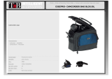
SCHEMA A BLOCCHI - BLOCK DIAGRAM
BLOCKSCHALTBILD - SCHEMAS FONCTIONNELS
DIMENSIONI / DIMENSIONS
ABMESSUNGEN / DIMENSIONS
43

DRK 10 accessorio
Accessory DRK 10
Appeso
Hanging on
INSTALLAZIONE INSTALLATION
INSTALLATIONEN INSTALLATIONS
Phase 1
Phase 2
Phase 4
Phase 6
Phase 5
Phase 8
Phase 9
Phase 7
Phase 10
Phase 3
Appeso
Hanging on
INCLINAZIONE INCLINATION
NEIGUNG INCLINAISON
3°
0°
6°
10°
8°
4.5°
1.5°
DVA T12
10°
8°
6°
45
46

DRK 10 accessorio
Accessory DRK 10
Appeso
Hanging on
INSTALLAZIONE INSTALLATION
INSTALLATIONEN INSTALLATIONS
Appeso
Hanging on
Phase 1
Phase 2
0°0° 0°0°
5°5° 5°5°
2,5°2,5°
GROUND STACKED
USE ONLY
GROUND STACKED
USE ONLY
2,5°2,5°
-2,5°-2,5° -2,5°-2,5°
-7,5°-7,5° -7,5°-7,5°
-5°-5° -5°-5°
INCLINAZIONE INCLINATION
NEIGUNG INCLINAISON
3°
0°
6°
10°
8°
4.5°
1.5°
DVA T12
2
1
2
2
2
Phase 3
Phase 4
Phase 5
Phase 6
Phase 5
Phase 6
47
48

Utilizzo in appoggio verticale (DVA T4 montaggio “Ground stacking”)
Supported use (DVA T4 ““Ground stacking” assembling)
DVA T12 + DVA S30
(DRK-10 support)
Sollevatore per diffusori - opzione DRL 45
Lift for speakers - DRL 45 option
Nota:
Utilizzare il sollevatore solo con l’accessorio
DRK 10 (flybar)
Note:
To use the lift of speaker only with DRK 10
accessory (flybar)
Contattare dB Technologies per gli accessori da utilizzare a corredo.
Si declina ogni responsabilità da un utilizzo inappropriato degli accessori o di dispositivi aggiuntivi non idonei allo
scopo.
Contact dB Technologies for accessories to be used with speakers.
Will not accept any responsibilty when inappropriate accessories or not suitable additional devices are used.
Kontaktieren sie dBTechnologies für passendes Lautsprecherzubehör.
Falls unpassendes Zubehör verwendet wird, wird jegliche Haftung ausgeschlossen.
Contact dBTechnologies pour les accessoires à utiliser avec la machine.
N'accepterons pas toutes les responsabilités lorsque des accessoires inappropriés ou ne conviennent pas à des
dispositifs supplémentaires sont utilisés.
ISTRUZIONI DI SICUREZZA PER ACCESSORI /
ZUBEHÖR NSTRUCTIONS DE SÉCURITÉ
SAFETY INSTRUCTIONS FOR ACCESSORIES
SICHERHEITSHINWEISE / I POUR LES ACCESSOIRES
49
50
/