Page is loading ...

S-44GL
Processes
Description
Flux Cored (FCAW) Welding
Wire Feeder
OM-1534 045 215G
August 1998
Visit our website at
www.MillerWelds.com

Miller Electric manufactures a full line
of welders and welding related equipment.
For information on other quality Miller
products, contact your local Miller distributor
to receive the latest full line catalog or
individual catalog sheets. To locate your nearest
distributor or service agency call 1-800-4-A-Miller,
or visit us at www.MillerWelds.com on the web.
Thank you and congratulations on choosing Miller. Now
you can get the job done and get it done right. We know
you don’t have time to do it any other way.
That’s why when Niels Miller first started building arc
welders in 1929, he made sure his products offered
long-lasting value and superior quality. Like you, his
customers couldn’t afford anything less. Miller products
had to be more than the best they could be. They had to
be the best you could buy.
Today, the people that build and sell Miller products continue the
tradition. They’re just as committed to providing equipment and service
that meets the high standards of quality and value established in 1929.
This Owner’s Manual is designed to help you get the most out of your
Miller products. Please take time to read the Safety precautions. They will
help you protect yourself against potential hazards on the worksite. We’ve
made installation and operation quick and easy.
With Miller you can count on years of reliable
service with proper maintenance. And if for
some reason the unit needs repair, there’s a
Troubleshooting section that will help you
figure out what the problem is. The parts list
will then help you to decide which exact part
you may need to fix the problem. Warranty and
service information for your particular model
are also provided.
Miller is the first welding
equipment manufacturer in
the U.S.A. to be registered to
the ISO 9001 Quality System
Standard.
Working as hard as you do
– every power source from
Miller is backed by the most
hassle-free warranty in the
business.
From Miller to You
Miller offers a Technical
Manual which provides
more detailed service and
parts information for your
unit. To obtain a Technical
Manual, contact your local
distributor. Your distributor
can also supply you with
Welding Process Manuals
such as SMAW, GTAW,
GMAW, and GMAW-P.

TABLE OF CONTENTS
Section No. Page No.
SECTION 1 – SAFETY RULES FOR OPERATION OF ARC WELDING POWER SOURCE
1-1. Introduction 1. . . . . . . . . . . . . . . . . . . . . . . . . . . . . . . . . . . . . . . . . . . . . . . . .
1-2. General Precautions 1. . . . . . . . . . . . . . . . . . . . . . . . . . . . . . . . . . . . . . . . .
1-3. Arc Welding 4. . . . . . . . . . . . . . . . . . . . . . . . . . . . . . . . . . . . . . . . . . . . . . . . .
1-4. Standards Booklet Index 5. . . . . . . . . . . . . . . . . . . . . . . . . . . . . . . . . . . . . .
SECTION 2 – SAFETY PRECAUTIONS AND SIGNAL WORDS
2-1. General Information And Safety 6. . . . . . . . . . . . . . . . . . . . . . . . . . . . . . .
2-2. Safety Alert Symbol And Signal Words 6. . . . . . . . . . . . . . . . . . . . . . . . .
SECTION 3 – SPECIFICATIONS
3-1. Description 7. . . . . . . . . . . . . . . . . . . . . . . . . . . . . . . . . . . . . . . . . . . . . . . . .
SECTION 4 – INSTALLATION OR RELOCATION
4-1. Location 7. . . . . . . . . . . . . . . . . . . . . . . . . . . . . . . . . . . . . . . . . . . . . . . . . . . .
4-2. Drive Motor Vent Screw 7. . . . . . . . . . . . . . . . . . . . . . . . . . . . . . . . . . . . . .
4-3. Wire Guide And Drive Roll Installation 8. . . . . . . . . . . . . . . . . . . . . . . . . .
4-4. Welding Gun Connections 8. . . . . . . . . . . . . . . . . . . . . . . . . . . . . . . . . . . .
4-5. Voltage Sensing Lead Connection 9. . . . . . . . . . . . . . . . . . . . . . . . . . . . .
4-6. Shielding Gas Connection (Models With Optional Gas Valve) 9. . . . . .
4-7. 115 Volts AC Connection (Models With Optional Gas Valve) 9. . . . . . .
4-8. Welding Power Source/Wire Feeder Weld Cable Connections 9. . . . .
4-9. Welding Wire Installation 10. . . . . . . . . . . . . . . . . . . . . . . . . . . . . . . . . . . . .
4-10. Welding Wire Threading 10. . . . . . . . . . . . . . . . . . . . . . . . . . . . . . . . . . . . . .
SECTION 5 – OPERATOR CONTROLS
5-1. Arc Length Control 11. . . . . . . . . . . . . . . . . . . . . . . . . . . . . . . . . . . . . . . . . . .
5-2. Jog Button 12. . . . . . . . . . . . . . . . . . . . . . . . . . . . . . . . . . . . . . . . . . . . . . . . . .
5-3. Polarity Switch 12. . . . . . . . . . . . . . . . . . . . . . . . . . . . . . . . . . . . . . . . . . . . . .
5-4. Optional Voltmeter 12. . . . . . . . . . . . . . . . . . . . . . . . . . . . . . . . . . . . . . . . . . .
5-5. Optional Remote Jog Switch 12. . . . . . . . . . . . . . . . . . . . . . . . . . . . . . . . . .
SECTION 6 – SEQUENCE OF OPERATION
6-1. Flux Core Arc Welding (FCAW) And Gas Metal Arc Welding (GMAW) . . .
13
6-2. Shutting Down 13. . . . . . . . . . . . . . . . . . . . . . . . . . . . . . . . . . . . . . . . . . . . . .
SECTION 7 – MAINTENANCE & TROUBLESHOOTING
7-1. Routine Maintenance 14. . . . . . . . . . . . . . . . . . . . . . . . . . . . . . . . . . . . . . . . .
7-2. Aligning Motor Gear And Drive Gears 14. . . . . . . . . . . . . . . . . . . . . . . . . .
7-3. Reinstallation Of Hub Assembly 15. . . . . . . . . . . . . . . . . . . . . . . . . . . . . . .
7-4. Overload Protection 15. . . . . . . . . . . . . . . . . . . . . . . . . . . . . . . . . . . . . . . . . .

7-5. Brush Inspection And Replacement 16. . . . . . . . . . . . . . . . . . . . . . . . . . . .
7-6. Troubleshooting 17. . . . . . . . . . . . . . . . . . . . . . . . . . . . . . . . . . . . . . . . . . . . .
SECTION 8 – ELECTRICAL DIAGRAMS
Diagram 8-1. Circuit Diagram 18. . . . . . . . . . . . . . . . . . . . . . . . . . . . . . . . . . . . . . . .
Section No. Page No.
SECTION 9 – PARTS LIST
Figure 9-1. Main Assembly 20. . . . . . . . . . . . . . . . . . . . . . . . . . . . . . . . . . . . . . . . . .
Optional Equipment 22. . . . . . . . . . . . . . . . . . . . . . . . . . . . . . . . . . . . . . . . . . . . . . . .
Figure 9-2. Switch, Magnetic Blowout 23. . . . . . . . . . . . . . . . . . . . . . . . . . . . . . . . .
Figure 9-3. Wire Drive & Gears 24. . . . . . . . . . . . . . . . . . . . . . . . . . . . . . . . . . . . . .
LIST OF CHARTS AND TABLES
Table 3-1. Specifications 7. . . . . . . . . . . . . . . . . . . . . . . . . . . . . . . . . . . . . . . . . . . .
Table 5-1. Arc Voltage Wire Speed 12. . . . . . . . . . . . . . . . . . . . . . . . . . . . . . . . . . .
Table 7-1. Maintenance Schedule 14. . . . . . . . . . . . . . . . . . . . . . . . . . . . . . . . . . . .
Table 7-2. Troubleshooting 17. . . . . . . . . . . . . . . . . . . . . . . . . . . . . . . . . . . . . . . . . .
Table 9-1. Drive Roll & Wire Guide Kits 25. . . . . . . . . . . . . . . . . . . . . . . . . . . . . . . .

OM-1534 Page 1
SECTION 1 – SAFETY RULES FOR OPERATION OF ARC WELDING POWER SOURCE
1-1. INTRODUCTION
We learn by experience. Learning safety through per-
sonal experience, like a child touching a hot stove is
harmful, wasteful, and unwise. Let the experience of
others teach you.
Safe practices developed from experience in the use of
welding and cutting are described in this manual. Re-
search, development, and field experience have
evolved reliable equipment and safe installation, opera-
tion, and servicing practices. Accidents occur when
equipment is improperly used or maintained. The rea-
son for the safe practices may not always be given.
Some are based on common sense, others may require
technical volumes to explain. It is wiser to follow the
rules.
Read and understand these safe practices before at-
tempting to install, operate, or service the equipment.
Comply with these procedures as applicable to the par-
ticular equipment used and their instruction manuals,
for personal safety and for the safety of others.
Failure to observe these safe practices may cause seri-
ous injury or death. When safety becomes a habit, the
equipment can be used with confidence.
These safe practices are divided into two Sections:
1-General Precautions, common to arc welding and cut-
ting; and 2-Arc Welding (and Cutting) (only).
Reference standards: Published Standards on safety
are also available for additional and more complete pro-
cedures than those given in this manual. They are listed
in the Standards Index in this manual. ANSI Z49.1 is the
most complete.
The National Electrical Code, Occupational Safety and
Health Administration, local industrial codes, and local
inspection requirements also provide a basis for equip-
ment installation, use, and service.
1-2. GENERAL PRECAUTIONS
Different arc welding processes, electrode alloys,
and fluxes can produce different fumes, gases, and
radiation levels. In addition to the information in
this manual, be sure to consult flux and electrode
manufacturers Material Safety Data Sheets
(MSDSs) for specific technical data and precaution-
ary measures concerning their material.
A. Burn Prevention
Wear protective clothing-gauntlet gloves designed for
use in welding, hat, and high safety-toe shoes. Button
shirt collar and pocket flaps, and wear cuffless trousers
to avoid entry of sparks and slag.
Wear helmet with safety goggles and glasses with side
shields underneath, appropriate filter lenses or plates
(protected by clear cover glass). This is a MUST for
welding or cutting, (and chipping) to protect the eyes
from radiant energy and flying metal. Replace cover
glass when broken, pitted, or spattered. See 1-3A.2.
Avoid oily or greasy clothing. A spark may ignite them.
Hot metal such as electrode stubs and workpieces
should never be handled without gloves.
Medical first aid and eye treatment. First aid facilities
and a qualified first aid person should be available for
each shift unless medical facilities are close by for im-
mediate treatment of flash burns of the eyes and skin
burns.
Ear plugs should be worn when working on overhead or
in a confined space. A hard hat should be worn when
others work overhead.
Flammable hair preparations should not be used by per-
sons intending to weld or cut.
B. Toxic Fume Prevention
Severe discomfort, illness or death can result from
fumes, vapors, heat, or oxygen enrichment or depletion
that welding (or cutting) may produce. Prevent them
with adequate ventilation as described in ANSI Stan-
dard Z49.1 listed in Standards Index. NEVER ventilate
with oxygen.
Lead -, cadmium -, zinc -, mercury -, and beryllium-bear-
ing and similar materials, when welded (or cut) may pro-
duce harmful concentrations of toxic fumes. Adequate
local exhaust ventilation must be used, or each person
in the area as well as the operator must wear an air-sup-
plied respirator. For beryllium, both must be used.
Metals coated with or containing materials that emit
toxic fumes should not be heated unless coating is re-
moved from the work surface, the area is well ventilated
and, if necessary, while wearing an air-supplied respira-
tor.
Work in a confined space only while it is being ventilated
and, if necessary, while wearing an air-supplied respira-
tor.
Gas leaks in a confined space should be avoided.
Leaked gas in large quantities can change oxygen con-
centration dangerously. Do not bring gas cylinders into a
confined space.
Leaving confined space, shut OFF gas supply at source
to prevent possible accumulation of gases in the space if
downstream valves have been accidentally opened or
left open. Check to be sure that the space is safe before
re-entering it.
Vapors from chlorinated solvents can be decomposed
by the heat of the arc (or flame) to form PHOSGENE, a
highly toxic gas, and other lung and eye irritating prod-
ucts. The ultraviolet (radiant) energy of the arc can also
decompose trichloroethylene and perchloroethylene
vapors to form phosgene. DO NOT WELD or cut where
solvent vapors can be drawn into the welding or cutting

OM-1534 Page 2
atmosphere or where the radiant energy can penetrate
to atmospheres containing even minute amounts of
trichloroethylene or perchloroethylene.
C. Fire and Explosion Prevention
Causes of fire and explosion are: combustibles reached
by the arc, flame, flying sparks, hot slag or heated mate-
rial; misuse of compressed gases and cylinders; and
short circuits.
BE AWARE THAT flying sparks or falling slag can pass
through cracks, along pipes, through windows or doors,
and through wall or floor openings, out of sight of the
goggled operator. Sparks and slag can fly 35 feet.
To prevent fires and explosion:
Keep equipment clean and operable, free of oil, grease,
and (in electrical parts) of metallic particles that can
cause short circuits.
If combustibles are in area, do NOT weld or cut. Move
the work if practicable, to an area free of combustibles.
Avoid paint spray rooms, dip tanks, storage areas, ven-
tilators. If the work cannot be moved, move comb-
ustibles at least 35 feet away out of reach of sparks and
heat; or protect against ignition with suitable and snug-
fitting, fire-resistant covers or shields.
Walls touching combustibles on opposite sides should
not be welded on (or cut). Walls, ceilings, and floor near
work should be protected by heat-resistant covers or
shields.
Fire watcher must be standing by with suitable fire extin-
guishing equipment during and for some time after weld-
ing or cutting if:
a. appreciable combustibles (including building
construction) are within 35 feet
b. appreciable combustibles are further than 35
feet but can be ignited by sparks
c. openings (concealed or visible) in floors or walls
within 35 feet may expose combustibles to
sparks
d. combustibles adjacent to walls, ceilings, roofs,
or metal partitions can be ignited by radiant or
conducted heat.
Hot work permit should be obtained before operation to
ensure supervisor’s approval that adequate precau-
tions have been taken.
After work is done, check that area is free of sparks,
glowing embers, and flames.
An empty container that held combustibles, or that can
produce flammable or toxic vapors when heated, must
never be welded on or cut, unless container has first
been cleaned as described in AWS Standard A6.0,
listed 7 in Standards Index.
This includes: a thorough steam or caustic cleaning (or
a solvent or water washing, depending on the combusti-
ble’s solubility) followed by purging and inerting with ni-
trogen or carbon dioxide, and using protective equip-
ment as recommended in A6.0. Waterfilling just below
working level may substitute for inerting.
A container with unknown contents should be cleaned
(see preceding paragraph). Do NOT depend on sense
of smell or sight to determine if it is safe to weld or cut.
Hollow castings or containers must be vented before
welding or cutting. They can explode.
Explosive atmospheres. Never weld or cut where the air
may contain flammable dust, gas, or liquid vapors (such
as gasoline).
D. Compressed Gas Equipment
Standard precautions. Comply with precautions in this
manual, and those detailed in CGA Standard P-1, SAFE
HANDLING OF COMPRESSED GASES IN CYLIN-
DERS, listed 11 in Standards Index.
1. Pressure Regulators
Regulator relief valve is designed to protect only the
regulator from overpressure; it is not intended to protect
any downstream equipment. Provide such protection
with one or more relief devices.
Never connect a regulator to a cylinder containing gas
other than that for which the regulator was designed.
Remove faulty regulator from service immediately for
repair (first close cylinder valve). The following symp-
toms indicate a faulty regulator:
Leaks-if gas leaks externally.
Excessive Creep-if delivery pressure continues to rise
with downstream valve closed.
Faulty Gauge-if gauge pointer does not move off stop
pin when pressurized, nor returns to stop pin after pres-
sure release.
Repair. Do NOT attempt to repair. Send faulty regula-
tors for repair to manufacturer’s designated repair cen-
ter, where special techniques and tools are used by
trained personnel.
2. Cylinders
Cylinders must be handled carefully to prevent leaks
and damage to their walls, valves, or safety devices:
Avoid electrical circuit contact with cylinders including
third rails, electrical wires, or welding circuits. They can
produce short circuit arcs that may lead to a serious ac-
cident. (See 1-3C.)
ICC or DOT marking must be on each cylinder. It is an
assurance of safety when the cylinder is properly han-
dled.
Identifying gas content. Use only cylinders with name of
gas marked on them; do not rely on color to identify gas
content. Notify supplier if unmarked. NEVER DEFACE
or alter name, number, or other markings on a cylinder. It
is illegal and hazardous.
Empties: Keep valves closed, replace caps securely;
mark MT; keep them separate from FULLS and return
promptly.
Prohibited use. Never use a cylinder or its contents for
other than its intended use, NEVER as a support or
roller.

OM-1534 Page 3
Locate or secure cylinders so they cannot be knocked
over.
Passageways and work areas. Keep cylinders clear of
areas where they may be struck.
Transporting cylinders. With a crane, use a secure sup-
port such as a platform or cradle. Do NOT lift cylinders
off the ground by their valves or caps, or by chains,
slings, or magnets.
Do NOT expose cylinders to excessive heat, sparks,
slag, and flame, etc. that may cause rupture. Do not al-
low contents to exceed 130°F. Cool with water spray
where such exposure exists.
Protect cylinders particularly valves from bumps, falls,
falling objects, and weather. Replace caps securely
when moving cylinders.
Stuck valve. Do NOT use a hammer or wrench to open a
cylinder valve that can not be opened by hand. Notify
your supplier.
Mixing gases. Never try to mix any gases in a cylinder.
Never refill any cylinder.
Cylinder fittings should never be modified or ex-
changed.
3. Hose
Prohibited use. Never use hose other than that de-
signed for the specified gas. A general hose identifica-
tion rule is: red for fuel gas, green for oxygen, and black
for inert gases.
Use ferrules or clamps designed for the hose (not ordi-
nary wire or other substitute) as a binding to connect
hoses to fittings.
No copper tubing splices. Use only standard brass fit-
tings to splice hose.
Avoid long runs to prevent kinks and abuse. Suspend
hose off ground to keep it from being run over, stepped
on, or otherwise damaged.
Coil excess hose to prevent kinks and tangles.
Protect hose from damage by sharp edges, and by
sparks, slag, and open flame.
Examine hose regularly for leaks, wear, and loose con-
nections. Immerse pressured hose in water; bubbles in-
dicate leaks.
Repair leaky or worn hose by cutting area out and splic-
ing (1-2D3). Do NOT tape.
4. Proper Connections
Clean cylinder valve outlet of impurities that may clog
orifices and damage seats before connecting regulator.
Except for hydrogen, crack valve momentarily, pointing
outlet away from people and sources of ignition. Wipe
with a clean lintless cloth.
Match regulator to cylinder. Before connecting, check
that the regulator label and cylinder marking area, and
that the regulator inlet and cylinder outlet match.
NEVER CONNECT a regulator designed for a particular
gas or gases to a cylinder containing any other gas.
Tighten connections. When assembling threaded con-
nections, clean and smooth seats where necessary.
Tighten. If connection leaks, disassemble, clean, and
retighten using properly fitting wrench.
Adapters. Use a CGA adapter (available from your sup-
plier) between cylinder and regulator, if one is required.
use two wrenches to tighten adapter marked RIGHT
and LEFT HAND threads.
Regulator outlet (or hose) connections may be identified
by right hand threads for oxygen and left hand threads
(with grooved hex on nut or shank) for fuel gas.
5. Pressurizing Steps:
Drain regulator of residual gas through suitable vent be-
fore opening cylinder (or manifold valve) by turning ad-
justing screw in (clockwise). Draining prevents exces-
sive compression heat at high pressure seat by allowing
seat to open on pressurization. Leave adjusting screw
engaged slightly on single-stage regulators.
Stand to side of regulator while opening cylinder valve.
Open cylinder valve slowly so that regulator pressure in-
creases slowly. When gauge is pressurized (gauge
reaches regulator maximum) leave cylinder valve in fol-
lowing position: For oxygen, and inert gases, open fully
to seal stem against possible leak. For fuel gas, open to
less than one turn to permit quick emergency shutoff.
Use pressure charts (available from your supplier) for
safe and efficient, recommended pressure settings on
regulators.
Check for leaks on first pressurization and regularly
there-after. Brush with soap solution (capfull of Ivory
Liquid* or equivalent per gallon of water). Bubbles indi-
cate leak. Clean off soapy water after test; dried soap is
combustible.
E. User Responsibilities
Remove leaky or defective equipment from service im-
mediately for repair. See User Responsibility statement
in equipment manual.
F. Leaving Equipment Unattended
Close gas supply at source and drain gas.
G. Rope Staging-Support
Rope staging-support should not be used for welding or
cutting operation; rope may burn.
*Trademark of Proctor & Gamble.

OM-1534 Page 4
1-3. ARC WELDING
Comply with precautions in 1-1, 1-2, and this section.
Arc Welding, properly done, is a safe process, but a
careless operator invites trouble. The equipment carries
high currents at significant voltages. The arc is very
bright and hot. Sparks fly, fumes rise, ultraviolet and in-
frared energy radiates, weldments are hot, and com-
pressed gases may be used. The wise operator avoids
unnecessary risks and protects himself and others from
accidents. Precautions are described here and in stan-
dards referenced in index.
A. Burn Protection
Comply with precautions in 1-2.
The welding arc is intense and visibly bright. Its radiation
can damage eyes, penetrate lightweight clothing, reflect
from light-colored surfaces, and burn the skin and eyes.
Skin burns resemble acute sunburn, those from gas-
shielded arcs are more severe and painful. DON’T GET
BURNED; COMPLY WITH PRECAUTIONS.
1. Protective Clothing
Wear long-sleeve clothing (particularly for gas-shielded
arc) in addition to gloves, hat, and shoes (1-2A). As nec-
essary, use additional protective clothing such as
leather jacket or sleeves, flame-proof apron, and fire-re-
sistant leggings. Avoid outer garments of untreated cot-
ton.
Bare skin protection. Wear dark, substantial clothing.
Button collar to protect chest and neck and button pock-
ets to prevent entry of sparks.
2. Eye and Head Protection
Protect eyes from exposure to arc. NEVER look at an
electric arc without protection.
Welding helmet or shield containing a filter plate shade
no. 12 or denser must be used when welding. Place over
face before striking arc.
Protect filter plate with a clear cover plate.
Cracked or broken helmet or shield should NOT be
worn; radiation can pass through to cause burns.
Cracked, broken, or loose filter plates must be replaced
IMMEDIATELY. Replace clear cover plate when broken,
pitted, or spattered.
Flash goggles with side shields MUST be worn under
the helmet to give some protection to the eyes should
the helmet not be lowered over the face before an arc is
struck. Looking at an arc momentarily with unprotected
eyes (particularly a high intensity gas-shielded arc) can
cause a retinal burn that may leave a permanent dark
area in the field of vision.
3. Protection of Nearby Personnel
Enclosed welding area. For production welding, a sepa-
rate room or enclosed bay is best. In open areas, sur-
round the operation with low-reflective, non-combusti-
ble screens or panels. Allow for free air circulation, par-
ticularly at floor level.
Viewing the weld. Provide face shields for all persons
who will be looking directly at the weld.
Others working in area. See that all persons are wearing
flash goggles.
Before starting to weld, make sure that screen flaps or
bay doors are closed.
B. Toxic Fume Prevention
Comply with precautions in 1-2B.
Generator engine exhaust must be vented to the out-
side air. Carbon monoxide can kill.
C. Fire and Explosion Prevention
Comply with precautions in 1-2C.
Equipment’s rated capacity. Do not overload arc weld-
ing equipment. It may overheat cables and cause a fire.
Loose cable connections may overheat or flash and
cause a fire.
Never strike an arc on a cylinder or other pressure ves-
sel. It creates a brittle area that can cause a violent rup-
ture or lead to such a rupture under rough handling.
D. Compressed Gas Equipment
Comply with precautions in 1-2D.
E. Shock Prevention
Exposed hot conductors or other bare metal in the weld-
ing circuit, or in ungrounded, electrically-HOT equip-
ment can fatally shock a person whose body becomes a
conductor. DO NOT STAND, SIT, LIE, LEAN ON, OR
TOUCH a wet surface when welding, without suitable
protection.
To protect against shock:
Wear dry insulating gloves and body protection. Keep
body and clothing dry. Never work in damp area without
adequate insulation against electrical shock. Stay on a
dry duckboard, or rubber mat when dampness or sweat
can not be avoided. Sweat, sea water, or moisture be-
tween body and an electrically HOT part or grounded
metal reduces the electrical resistance, and could en-
able dangerous and possibly lethal currents to flow
through the body.
A voltage will exist between the electrode and any con-
ducting object in the work circuit. Examples of conduct-
ing objects include, but are not limited to, buildings, elec-
trical tools, work benches, welding power source cases,
workpieces, etc. Never touch the electrode and any
metal object unless the welding power source is
off.
1. Grounding the Equipment
Arc welding equipment must be grounded according to
the National Electrical Code, and the work must be
grounded according to ANSI Z49.1 “Safety In Welding
And Cutting.”
When installing, connect the frames of each unit such as
welding power source, control, work table, and water cir-
culator to the building ground. Conductors must be ade-

OM-1534 Page 5
quate to carry ground currents safely. Equipment made
electrically HOT by stray current may shock, possibly
fatally. Do NOT GROUND to electrical conduit, or to a
pipe carrying ANY gas or flammable liquid such as oil or
fuel.
Three-phase connection. Check phase requirements of
equipment before installing. If only 3-phase power is
available, connect single-phase equipment to only two
wires of the 3-phase line. Do NOT connect the equip-
ment ground lead to the third (live) wire, or the equip-
ment will become electrically HOT-a dangerous condi-
tion that can shock, possibly fatally.
Before welding, check ground for continuity. Be sure
conductors are touching bare metal of equipment
frames at connections.
If a line cord with a ground lead is provided with the
equipment for connection to a switchbox, connect the
ground lead to the grounded switchbox. If a three-prong
plug is added for connection to a grounded mating re-
ceptacle, the ground lead must be connected to the
ground prong only. If the line cord comes with a three-
prong plug, connect to a grounded mating receptacle.
Never remove the ground prong from a plug, or use a
plug with a broken off ground prong.
2. Electrode Holders
Fully insulated electrode holders should be used. Do
NOT use holders with protruding screws.
3. Connectors
Fully insulated lock-type connectors should be used to
join welding cable lengths.
4. Cables
Frequently inspect cables for wear, cracks and damage.
IMMEDIATELY REPLACE those with excessively worn
or damaged insulation to avoid possibly-lethal shock
from bared cable. Cables with damaged areas may be
taped to give resistance equivalent to original cable.
Keep cable dry, free of oil and grease, and protected
from hot metal and sparks.
5. Terminals And Other Exposed Parts
Terminals and other exposed parts of electrical units
should have insulating covers secured before opera-
tion.
6. Electrode
a. Equipment with output on/off control (contac-
tor)
Welding power sources for use with the gas
metal arc welding (GMAW), gas tungsten arc
welding (GTAW) and similar processes nor-
mally are equipped with devices that permit on-
off control of the welding power output. When
so equipped the electrode wire becomes elec-
trically HOT when the power source switch is
ON and the welding gun switch is closed. Never
touch the electrode wire or any conducting ob-
ject in contact with the electrode circuit unless
the welding power source is off.
b. Equipment without output on/off control (no
contactor)
Welding power sources used with shielded
metal arc welding (SMAW) and similar proc-
esses may not be equipped with welding power
output on-off control devices. With such equip-
ment the electrode is electrically HOT when the
power switch is turned ON. Never touch the
electrode unless the welding power source is
off.
7. Safety Devices
Safety devices such as interlocks and circuit breakers
should not be disconnected or shunted out.
Before installation, inspection, or service, of equipment,
shut OFF all power and remove line fuses (or lock or
red-tag switches) to prevent accidental turning ON of
power. Disconnect all cables from welding power
source, and pull all 115 volts line-cord plugs.
Do not open power circuit or change polarity while weld-
ing. If, in an emergency, it must be disconnected, guard
against shock burns, or flash from switch arcing.
Leaving equipment unattended. Always shut OFF and
disconnect all power to equipment.
Power disconnect switch must be available near the
welding power source.
F. Protection For Wearers of Electronic Life Sup-
port Devices (Pacemakers)
Magnetic fields from high currents can affect pacemak-
er operation. Persons wearing electronic life support
equipment (pacemaker) should consult with their doctor
before going near arc welding, gouging, or spot welding
operations.
1-4. STANDARDS BOOKLET INDEX
For more information, refer to the following standards or
their latest revisions and comply as applicable:
1. ANSI Standard Z49.1, SAFETY IN WELDING
AND CUTTING obtainable from the American
Welding Society, 550 N.W. LeJeune Rd, Miami,
FL 33126.
2. NIOSH, SAFETY AND HEALTH IN ARC WELD-
ING AND GAS WELDING AND CUTTING ob-
tainable from the Superintendent of Documents,
U.S. Government Printing Office, Washington,
D.C. 20402.
3. OSHA, SAFETY AND HEALTH STANDARDS,
29CFR 1910, obtainable from the Superinten-
dent of Documents, U.S. Government Printing
Office, Washington, D.C. 20402.
4. ANSI Standard Z87.1, SAFE PRACTICES FOR
OCCUPATION AND EDUCATIONAL EYE AND
FACE PROTECTION obtainable from the Ameri-
can National Standards Institute, 1430 Broad-
way, New York, NY 10018.

OM-1534 Page 6
5. ANSI Standard Z41.1, STANDARD FOR MEN’S
SAFETY-TOE FOOTWEAR obtainable from the
American National Standards Institute, 1430
Broadway, New York, NY 10018.
6. ANSI Standard Z49.2, FIRE PREVENTION IN
THE USE OF CUTTING AND WELDING PROC-
ESSES obtainable from the American National
Standards Institute, 1430 Broadway, New York,
NY 10018.
7. AWS Standard A6.0, WELDING AND CUTTING
CONTAINERS WHICH HAVE HELD COMBUS-
TIBLES obtainable from the American Welding
Society, 550 N.W. LeJeune Rd, Miami, FL 33126.
8. NFPA Standard 51, OXYGEN-FUEL GAS SYS-
TEMS FOR WELDING, CUTTING, AND ALLIED
PROCESSES obtainable from the National Fire
Protection Association, Batterymarch Park,
Quincy, MA 02269.
9. NFPA Standard 70, NATIONAL ELECTRICAL
CODE obtainable from the National Fire Protec-
tion Association, Batterymarch Park, Quincy, MA
02269.
10. NFPA Standard 51B, CUTTING AND WELDING
PROCESSES obtainable from the National Fire
Protection Association, Batterymarch Park,
Quincy, MA 02269.
11. CGA Pamphlet P-1, SAFE HANDLING OF
COMPRESSED GASES IN CYLINDERS obtain-
able from the Compressed Gas Association,
1235 Jefferson Davis Highway, Suite 501, Ar-
lington, VA 22202.
12. CSA Standard W117.2, CODE FOR SAFETY IN
WELDING AND CUTTING obtainable from the
Canadian Standards Association, Standards
Sales, 178 Rexdale Boulevard, Rexdale, On-
tario, Canada M9W 1R3.
13. NWSA booklet, WELDING SAFETY BIBLIOG-
RAPHY obtainable from the National Welding
Supply Association, 1900 Arch Street, Philadel-
phia, PA 19103.
14. American Welding Society Standard AWSF4.1,
RECOMMENDED SAFE PRACTICES FOR
THE PREPARATION FOR WELDING AND
CUTTING OF CONTAINERS AND PIPING
THAT HAVE HELD HAZARDOUS SUB-
STANCES, obtainable from the American Weld-
ing Society, 550 N.W. LeJeune Rd, Miami, FL
33126.
15. ANSI Standard Z88.2, PRACTICE FOR RESPI-
RATORY PROTECTION, obtainable from the
American National Standards Institute, 1430
Broadway, New York, NY 10018.
SECTION 2 – SAFETY PRECAUTIONS AND SIGNAL WORDS
2-1. GENERAL INFORMATION AND SAFETY
A. General
Information presented in this manual and on various la-
bels, tags, and plates on the unit pertains to equipment
design, installation, operation, maintenance, and
troubleshooting which should be read, understood, and
followed for the safe and effective use of this equipment.
The nameplate of this unit uses international symbols
for labeling the front panel controls. The symbols also
appear at the appropriate section in the text.
B. Safety
The installation, operation, maintenance, and trouble-
shooting of arc welding equipment requires practices
and procedures which ensure personal safety and the
safety of others. Therefore, this equipment is to be in-
stalled, operated, and maintained only by qualified per-
sons in accordance with this manual and all applicable
codes such as, but not limited to, those listed at the end
of Section 1 – Safety Rules For Operation Of Arc Weld-
ing Power Source.
2-2. SAFETY ALERT SYMBOL AND SIGNAL
WORDS
The following safety alert symbol and signal words are
used throughout this manual to call attention to and
identify different levels of hazard and special instruc-
tions.
This safety alert symbol is used with the signal
words WARNING and CAUTION to call atten-
tion to the safety statements.
WARNING statements identify procedures or
practices which must be followed to avoid seri-
ous personal injury or loss of life.
CAUTION statements identify procedures or
practices which must be followed to avoid minor
personal injury or damage to this equipment.
IMPORTANT statements identify special instructions
necessary for the most efficient operation of this equip-
ment.

OM-1534 Page 7
SECTION 3 – SPECIFICATIONS
Table 3-1. Specifications
Electrode Wire
Diameter Capability
Speed
Range
Max. Weld
Output @ 100%
Weight
Net Ship
1/16 Thru 1/8 in.
(1.6 Thru 3.2 mm)
100 Volts @ 115 lbs.
(52 kg)
125 lbs.
(57 kg)
Depends On
Arc Voltage
750 Amperes
Duty Cycle
ST-045 405-A
16-3/4 in.
(426 mm)
31-1/4 in.
(794 mm)
25 in.
(635 mm)
Figure 3-1. Wire Feeder Dimensions
3-1. DESCRIPTION
This unit is a heavy-duty wire feeder designed to run off
the arc voltage of a constant current or constant voltage
dc welding power source. The four drive roll system is
designed for use with 1/16 in. (1.6 mm) through 1/8 in.
(3.2 mm) flux-cored or self-shielding welding wire.
All necessary equipment and controls are provided with
the wire feeder to supply welding wire to the gun.
An optional gas valve, voltmeter, and/or remote jog con-
trol can be provided.
SECTION 4 – INSTALLATION OR RELOCATION
4-1. LOCATION (Figure 3-1)
The service life and efficiency of this unit and associated
components are reduced when they are subjected to
high levels of dust, dirt, moisture, corrosive vapors, and
extreme heat.
A proper installation site should be selected for the wire
feeder if the unit is to provide dependable service. Lead
lengths must be considered when installing the
unit.Suitable space should be maintained around the
unit for making necessary connections and for mainte-
nance functions.
4-2. DRIVE MOTOR VENT SCREW
The drive motor is provided with a vent screw which
must be removed before operating the wire feeder. Re-
move right side panel to gain access to the drive motor.
CAUTION: PRESSURE IN WIRE DRIVE
MOTOR GEAR BOX will damage motor.
• Remove vent screw before operation.
Warranty is void if the vent screw is not removed
before operation.

OM-1534 Page 8
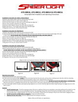
4-3. WIRE GUIDE AND DRIVE ROLL INSTALLA-
TION (Figure 4-1)
Upon initial installation, or as a result of changes in wire
size and type, it is necessary to install the required drive
rolls and wire guides. Select drive rolls according to
Table 9-1.
After obtaining the appropriate drive rolls and wire
guides, proceed as follows:
A. Wire Guide Installation
1. Loosen the wire guide securing screws.
IMPORTANT: Wire guides should be installed so that
the tip(s) of the guide is as close to the drive roll as possi-
ble without touching.
2. Install wire guides as illustrated in Figure 4-1. Ad-
just after installing drive rolls, and secure by tight-
ening securing screws.
B. Wire Guide And Drive Roll Installation
1. Turn nut one click until lobes of nut line up with
lobes of drive roll carrier.
2. Slide drive roll onto drive roll carrier. Turn nut one
click.
IMPORTANT: When the grooves become worn, re-
verse rolls to locate unused groove in position to feed
wire.
IMPORTANT: The alignment of the wire drive assembly
is factory set and should not require readjustment. If
readjustment of the motor gear and drive gears is nec-
essary, refer to Section 7-2.
4-4. WELDING GUN CONNECTIONS
A. Gun Connector To Drive Assembly (Provides
Weld Power And Shielding Gas, If Applicable)
(Figure 4-1)
IMPORTANT: The outlet guide is provided as part of the
gun or gun adapter assembly.
1. Loosen the gun/feeder connector securing knob.
IMPORTANT: The outlet guide should be installed so
that tip of guide is as close to the drive rolls as possible
without touching.
2. Insert the gun/feeder connector, or gun/feeder
adapter if required, which includes installed outlet
guide, into drive assembly opposite inlet guide.
3. Tighten gun/feeder connector securing knob.
ST-070 887-F
Pressure
Adjustment
Knob
Wire Guide
Securing Screw
Wire
Drive Roll
Drive Roll
Nut
Drive Roll
Carrier
Drive
Gear
Gear
Cover
Inlet
Guide
Drive
Motor
Gun Feeder
Connector
Opening
Weld
Cable
Terminal
Securing
Knob
Wire
Guide
Securing
Screw
Intermediate
Wire Guide
Motor
Gear
Figure 4-1. Drive Roll And Wire Guide Installation On Four Drive Roll Units

OM-1534 Page 9
B. Shielding Gas (If Applicable)
An integral gas input fitting is provided on the wire drive
assembly for guns utilizing this type of connection. If the
gun requires a separate shielding gas connection, dis-
connect the hose from the gas fitting on drive assembly,
install proper fittings or connectors, and connect to gas
hose from gun.
C. Weld Cable (If Applicable)
WARNING: ELECTRIC SHOCK can kill.
• Do not touch live electrical parts.
• Shut down welding power source and discon-
nect input power employing lockout/tagging
procedures before making weld cable con-
nections.
Lockout/tagging procedures consist of pad-
locking line disconnect switch in open position,
removing fuses from fuse box, or shutting off
and red-tagging circuit breaker or other discon-
necting device.
• Stop engine on welding generator before
working on wire feeder.
ARCING can damage weld cable terminal.
• Clean weld cable terminal before connecting
weld cable if necessary.
• Tighten terminal nut securely.
Loose or dirty connections can cause erratic
weld output.
Connect the weld cable from the gun, if applicable, to the
front weld cable terminal on the drive assembly.
4-5. VOLTAGE SENSING LEAD CONNECTION
Connect the voltage sensing lead clamp to the
workpiece.
4-6. SHIELDING GAS CONNECTION (Models
With Optional Gas Valve)
Obtain a shielding gas hose of proper size, type, and
length and a gas fitting with 5/8-18 right-hand threads to
make shielding gas connection to control box. Proceed
as follows:
1. Install gas fitting onto one end of shielding gas
hose.
2. Route end of gas hose with fitting to gas input fit-
ting on gas valve on rear of control box.
3. Route and connect remaining end of hose to
regulator/flowmeter on shielding gas supply.
4-7. 115 VOLTS AC CONNECTION (Models With
Optional Gas Valve)
The optional gas valve require 115 volts ac to function.
Connect the power cord from the wire feeder gas valve
to a 115 volts ac, 60 Hz receptacle when use of the gas
valve is desired.
4-8. WELDING POWER SOURCE/WIRE FEEDER
WELD CABLE CONNECTIONS (Figure 4-2)
ELECTRIC SHOCK can kill.
• Do not touch live electrical parts.
• Shut down welding power source and discon-
nect input power employing lockout/tagging
procedures before making weld cable con-
nections.
Lockout/tagging procedures consist of pad-
locking line disconnect switch in open position,
removing fuses from fuse box, or shutting off
and red-tagging circuit breaker or other discon-
necting device.
• Stop engine on welding generator before
working on wire feeder.
ARCING can damage weld cable terminal.
• Clean weld cable terminal before connecting
weld cable if necessary.
• Tighten terminal nut securely.
Loose or dirty connections can cause erratic
weld output.
ST-140 743
Unit
Rear Panel
Weld Cable
From Welding
Power Source
Weld Cable
Terminal
Figure 4-2. Wire Feeder Installation

OM-1534 Page 10
Select and prepare weld cable according to information
in welding power source Owner’s Manual.
For Electrode Positive/Reverse Polarity connections
proceed as follows:
1. Route weld cable through grommet in rear panel
of wire feeder, and connect cable to weld cable
terminal. Be sure cable does not interfere with
wire feed.
2. Connect remaining end of cable to the Positive
(+) weld output terminal on welding power source
(see welding power source Owner’s Manual.)
3. Route and connect another weld cable of ade-
quate size and capacity from the Negative (–)
weld output terminal (see welding power source
Owner’s Manual) to workpiece.
IMPORTANT: For Electrode Negative/Straight Polarity
connections,reverse connections at the weld output ter-
minals. Be sure the POLARITY switch (see Section 5-3)
corresponds to the weld output connections.
4-9. WELDING WIRE INSTALLATION
A. Installation Of Spool-Type Wire (Figure 4-3)
1. Remove retaining ring.
2. Slide spool of wire onto hub so that wire feeds off
bottom of spool.
3. Rotate spool until hole in spool aligns with pin in
hub. Slide spool onto hub until it seats against
back flange of the hub.
4. Reinstall retaining ring onto hub.
Ref. ST-127 308-B
Unlocked
Retaining
Ring
Lock
Spanner
Nut
Wire
Retainer
Wire
Reel
Hub
Figure 4-3. Wire Reel And Reel-Type Wire
Installation
B. Installation Of Wire Reel And Reel-Type Wire
(Figure 4-3)
1. Remove retaining ring and, if applicable, wire reel
assembly from hub.
2. Lay wire reel assembly flat on table or floor.
3. Pull lock and turn. Remove spanner nut from wire
reel assembly.
4. Remove wire retainer, and install wire onto wire
reel. Be sure wire feeds off bottom of reel.
5. Reinstall wire retainer. Tighten spanner nut until
lock is in position over hole in wire retainer. Pull
lock and turn to insert locking pin into wire retain-
er.
6. Slide wire reel assembly onto hub, and turn as-
sembly until hub guide pin is seated in reel.
7. Reinstall retaining ring onto hub.
C. Adjustment Of Hub Tension (Figure 4-3)
Check the hub tension by slowly rotating the wire spool
or reel. The wire should unwind freely, but hub tension
should be sufficient to keep wire taut and prevent back-
lash when the wire feed stops. If adjustment is required,
loosen or tighten the hex nut on the end of the hub sup-
port shaft accordingly.
4-10. WELDING WIRE THREADING
WARNING: ELECTRIC SHOCK can kill;
MOVING PARTS can cause injury.
• Do not touch live electrical parts.
• Keep away from moving parts.
• Do not energize welding power source until
instructed to do so.
The welding wire and all metal parts in contact
with it are energized while welding.
WELDING WIRE can cause puncture
wounds; HOT SURFACES can burn skin.
• Do not press JOG button until instructed to do
so.
• Do not point gun toward any part of the body,
any conductive surface, or other personnel
when threading welding wire.
• Allow gun to cool before touching.
LOOSE WELDING WIRE can cause injury.
• Keep a firm hold on the wire during installa-
tion, removal, and threading operations.
Spooled wire has a tendency to unravel rapidly
when loosened from the spool.
1. Install the wire as instructed in Section 4-9.
2. Cut off any portion of the free end of the wire
which is not straight. If necessary, straighten wire
to remove cast. Be sure that the cut end is free
from rough surfaces to permit proper feeding.
3. Adjust hub tension according to Section 4-9C if
necessary.
4. Loosen knobs on the drive roll pressure adjust-
ments, pivot pressure adjustments free of the
covers, and pivot pressure gear assemblies
away to an open position.
5. Manually feed wire through the inlet wire guide
and intermediate wire guide, if applicable, and on
into the outlet wire guide. Feed approximately 4
in. (102 mm) of wire into the outlet wire guide.

OM-1534 Page 11
IMPORTANT: If the U-Cogged drive rolls do not align
properly when the gear cover is closed, pivot the gear
cover away from the drive gear, and rotate pressure
gear one tooth (see Section 4-3).
6. Pivot the pressure gear assemblies closed mak-
ing sure the teeth on the pressure gears mesh
with the teeth on the drive gears. The welding
wire must be in the grooves of the drive rolls. (See
Section 7-2 if wire does not feed in the grooves of
the drive rolls.)
7. Pivot the pressure adjustment knobs until the
washers on the pressure adjustments are seated
on top of the gear covers.
8. Turn the pressure adjustment knobs in a clock-
wise direction until the drive rolls are tight against
the welding wire. Do not overtighten. Further ad-
justment to attain desired clamping pressure can
be made after the welding power source and wire
feeder are put into operation.
9. Lay gun cable assembly out flat and straight (no
coils in the cable/conduit).
10. Energize the welding power source.
WARNING: ELECTRIC SHOCK can kill;
TANGLED WELDING WIRE can touch case
causing welding power source open-circuit
voltage to be present on case if JOG button
is pressed.
• Do not touch wire feeder case if JOG button
is pressed and wire does not feed.
• If wire stops feeding, turn off welding power
source, and determine the cause.
• Correct any hub tension, jammed wire, or gun
liner damage problems before trying to con-
tinue welding.
11. Press the JOG button (see WARNING block at
beginning of this Section). Wire feeds if drive roll
pressure is properly adjusted to prevent slippage.
If wire slippage is noticed, turn pressure adjust-
ment knob clockwise in 1/4 turn increments until
wire slippage stops. If excess pressure is re-
quired, check gun contact tube and gun liner for
correct size or obstructions. Release the JOG
button when welding wire extends approximately
1 in. (25 mm) out of gun tip.
12. Shut down welding power source.
SECTION 5 – OPERATOR CONTROLS
Fuse
Jog Button
Polarity Switch
Arc Control
Ref. ST-045 405-A
Figure 5-1. Operator Controls
5-1. ARC LENGTH CONTROL (Figure 5-1 And
Table 5-1)
The ARC LENGTH control provides a means of select-
ing the rate at which welding wire feeds into the weld.
Rotating the ARC LENGTH control clockwise increases
the wire feed speed. The scale surrounding the control
is calibrated in percent, zero to 100 (SHORT to LONG).
IMPORTANT: If the welding power source has a high or
low arc voltage, the wire feed speed is correspondingly
faster or slower.

OM-1534 Page 12
5-2. JOG BUTTON (Figure 5-1)
JOG
The JOG button is a momentary-contact switch. When
pressed, it completes the circuit to the motor without
having to strike an arc. This switch permits jogging of the
wire at the setting of the ARC CONTROL control, with-
out energizing the optional shielding gas valve.
5-3. POLARITY SWITCH (Figure 5-1)
()
+()
ELECTRODE
NEGATIVE
ELECTRODE
POSITIVE
Place the POLARITY switch in the ELECTRODE NEG-
ATIVE position when the weld output cables are con-
nected to the welding power source for electrode nega-
tive welding.
Place the POLARITY switch in the ELECTRODE POSI-
TIVE position when the weld output cables are con-
nected to the welding power source for electrode posi-
tive welding.
IMPORTANT: Be sure the weld cables from the welding
power source are connected for the position of the PO-
LARITY switch. If the weld output cable connections do
not correspond to the switch position, the welding wire
retracts into the gun.
5-4. OPTIONAL VOLTMETER
The voltmeter indicates dc arc voltage while welding.
When the JOG button is pressed, the voltmeter indi-
cates the voltage applied by the jog circuit.
5-5. OPTIONAL REMOTE JOG SWITCH
The Remote Jog switch allows the operator to jog weld-
ing wire from the work area. The Remote Jog switch
functions the same as the front panel JOG button.
The JOG button on the unit is also functional when the
Remote Jog switch is connected.
Table 5-1. Arc Voltage Wire Speed
Arc Length Control Setting
Arc Voltage 0 10 20 30 40 50 60 70 80 90 100
15 169 154 136 120 105 92 77 64 54 41 28
16 182 170 146 128 113 100 85 70 59 46 33
17 195 180 156 138 121 105 92 77 67 51 38
18 205 190 167 149 130 113 100 82 72 56 46
19 215 200 182 159 141 123 105 87 77 62 49
20 226 213 192 170 148 133 113 92 82 67 51
21 238 226 200 177 156 138 123 97 87 72 56
22 251 235 210 187 167 146 128 105 92 77 62
23 269 246 221 197 172 156 136 115 97 82 67
24 274 262 230 208 187 167 144 123 108 85 72
25 292 272 241 218 195 174 149 128 113 90 74
26 303 282 251 226 200 182 156 136 118 95 79
27 312 292 262 235 210 187 162 144 123 100 82
28 326 305 275 244 220 197 170 149 128 105 85
29 336 315 285 256 228 205 174 154 136 110 89
30 349 328 295 266 236 210 187 161 141 115 92
31 362 338 308 274 246 221 192 169 146 120 100
32 372 354 321 287 254 233 200 177 154 128 105
Inches Per Minute*
*Rounded Off

OM-1534 Page 13
SECTION 6 – SEQUENCE OF OPERATION
6-1. FLUX CORE ARC WELDING (FCAW) AND
GAS METAL ARC WELDING (GMAW)
WARNING: ELECTRIC SHOCK can kill;
MOVING PARTS can cause serious injury;
IMPROPER AIRFLOW AND EXPOSURE TO
ENVIRONMENT can damage internal parts.
• Do not touch live electrical parts.
• Keep away from moving parts.
• Keep all covers and panels in place while op-
erating.
Warranty is void if the wire feeder is operated
with any portion of the outer enclosure removed.
ARC RAYS, SPARKS, AND HOT SURFACES
can burn eyes and skin; NOISE can damage
hearing.
• Wear correct eye, ear, and body protection.
FUMES AND GASES can seriously harm
your health.
• Keep your head out of the fumes.
• Ventilate to keep from breathing fumes and
gases.
• If ventilation is inadequate, use approved
breathing device.
WELDING WIRE can cause puncture
wounds.
• Do not point gun toward any part of the body,
any conductive surface, or other personnel.
HOT METAL, SPATTER, AND SLAG can
cause fire and burns.
• Watch for fire.
• Keep a fire extinguisher nearby, and know
how to use it.
• Do not use near flammable material.
• Allow work and equipment to cool before han-
dling.
MAGNETIC FIELDS FROM HIGH CUR-
RENTS can affect pacemaker operation.
• Wearers should consult their doctor before
going near arc welding, gouging, or spot
welding operations.
See Section 1 – Safety Rules For Operation Of
Arc Welding Power Source.
1. Make all connections and thread welding wire as
instructed in Section 4.
2. Wear dry insulating gloves and clothing.
3. Connect work clamp to clean, bare metal at work-
piece.
4. Rotate the ARC LENGTH control to the desired
setting (see Section 5-1).
5. Turn on the shielding gas at the source, if applica-
ble.
6. Wear welding helmet with proper filter lens ac-
cording to ANSI Z49.1.
7. Energize welding power source.
WARNING: ELECTRIC SHOCK can kill.
• Do not touch live electrical parts.
• Do not touch welding wire or any metal part in
contact with it while welding.
The welding wire and all metal parts in contact
with it carry weld output when the welding power
source contactor is energized.
8. Touch the welding wire to workpiece to start the
arc and gas flow, if applicable. Wire feeds if drive
roll pressure is properly adjusted to prevent slip-
page. If wire slippage is noticed, adjust drive roll
pressure according to Section 4-10.
WARNING: ELECTRIC SHOCK can kill;
TANGLED WELDING WIRE can touch case
causing welding power source open-circuit
voltage to be present on case if JOG button
is pressed.
• Do not touch wire feeder case if JOG button is
pressed and wire does not feed.
• If wire stops feeding, turn off welding power
source, and determine the cause.
• Correct any hub tension, jammed wire, or gun
liner damage problems before trying to con-
tinue welding.
9. To stop wire feed, pull the gun away from the
workpiece.
6-2. SHUTTING DOWN
1. Shut down welding power source.
2. Turn off shielding gas at the source, if applicable.
3. Turn off all associated equipment.
WARNING: HIGH CONCENTRATION OF
SHIELDING GAS can harm health or kill.
• Shut off gas supply when not in use.

OM-1534 Page 14
SECTION 7 – MAINTENANCE & TROUBLESHOOTING
7-1. ROUTINE MAINTENANCE
IMPORTANT: Every six months inspect the labels on
this unit for legibility. All precautionary labels must be
maintained in a clearly readable state and replaced
when necessary. See Parts List for part number of pre-
cautionary labels.
WARNING: ELECTRIC SHOCK can kill.
• Do not touch live electrical parts.
• Shut down welding power source, and dis-
connect input power employing lockout/tag-
ging procedures before inspecting, maintain-
ing, or servicing.
Lockout/tagging procedures consist of pad-
locking line disconnect switch in open position,
removing fuses from fuse box, or shutting off
and red-tagging circuit breaker or other discon-
necting device.
• Stop engine on welding generator before
working on wire feeder.
MOVING PARTS can cause serious injury.
• Keep away from moving parts.
HOT SURFACES can cause severe burns.
• Allow cooling period before servicing.
Maintenance to be performed only by qualified
persons.
Table 7-1. Maintenance Schedule
Frequency* Maintenance
Every month. Units in heavy service environ-
ments: Check labels, hoses, and
cables; clean internal parts and
drive rolls.
Every 6
months.
Check all labels (see IMPOR-
TANT block, Section 7-1).
Clean drive rolls (see Section
7-1B).
*Frequency of service is based on units operated 40
hours per week. Increase frequency of maintenance if
usage exceeds 40 hours per week.
A. Internal Cleaning
WARNING: Read and follow safety informa-
tion at beginning of entire Section 7-1 before
proceeding.
Every six months, blow out or vacuum dust and dirt from
the inside of the wire feeder. Remove the outer enclo-
sure, and use a clean, dry airstream or vacuum suction
for the cleaning operation. If dirty or dusty conditions are
present, clean the unit monthly.
B. Cleaning Of Drive Rolls
WARNING: Read and follow safety informa-
tion at beginning of entire Section 7-1 before
proceeding.
MOVING PARTS can cause serious injury.
• Keep away from moving parts.
HIGH ROTATIONAL SPEED may cause dam-
age to drive rolls and injure personnel.
• Do not allow drive rolls to rotate at high speed
if compressed air is used for cleaning the
drive roll assembly.
It is necessary to remove the drive rolls for proper clean-
ing of the wire grooves (see Section 4-3 for removal and
installation instructions). Use a wire brush to clean rolls.
IMPORTANT: Failure to properly maintain the drive
rolls can result in a buildup of wire particles which de-
creases the efficiency of the wire feeding operation.
1. Remove the three drive roll securing screws from
each drive roll, and remove drive rolls (see Sec-
tion 4-3).
2. Using a wire brush, remove the buildup of wire
particles in the wire grooves.
3. Reinstall drive rolls according to Section 4-3.
4. Resume operation.
7-2. ALIGNING MOTOR GEAR AND DRIVE
GEARS (Figure 4-1)
WARNING: ELECTRIC SHOCK can kill.
• Do not touch live electrical parts.
• Shut down welding power source, and dis-
connect input power employing lockout/tag-
ging procedures before inspecting, maintain-
ing, or servicing.
Lockout/tagging procedures consist of pad-
locking line disconnect switch in open position,
removing fuses from fuse box, or shutting off
and red-tagging circuit breaker or other discon-
necting device.
• Stop engine on welding generator before
working on wire feeder.
MOVING PARTS can cause serious injury.
• Keep away from moving parts.
HOT SURFACES can cause severe burns.
• Allow cooling period before servicing.
Horizontal and vertical alignment of the motor gear with
the drive gears is factory set and should not require re-
adjustment. If readjustment becomes necessary, pro-
ceed as follows:

OM-1534 Page 15
A. Horizontal Adjustment
Behind the motor gear are spring washers. Turn motor
gear securing bolt in or out until motor gear is horizon-
tally aligned with drive gears.
B. Vertical Alignment
The wire drive housing is made with mounting holes of
sufficient clearance to provide adjustment of the hous-
ing up or down in relation to the motor gear.
CAUTION: IMPROPER CLEARANCE be-
tween motor gear and drive gears can result
in equipment damage.
• Maintain 0.003 in. (0.076 mm) clearance be-
tween motor gear and drive gears.
If proper clearance is not maintained, the gears
may wear severely, bind, break, or cause erratic
wire feed.
1. Loosen housing mounting bolts and weld cable
terminal nuts.
2. Slide wire drive housing away from motor gear
and insert a piece of standard writing paper (ap-
proximate thickness: 0.003 in.; 0.076 mm) be-
tween gears.
3. Slide wire drive housing toward motor gear so pa-
per is held in place but can be removed without
tearing.
4. Tighten housing mounting bolts and weld cable
terminal nuts, and remove paper.
7-3. REINSTALLATION OF HUB ASSEMBLY
(Figure 7-1)
If it becomes necessary to replace part or all of the hub
assembly, reinstall the new hub assembly as follows:
1. Remove hub assembly from hub support, and
disassemble discarding worn or broken parts.
2. Slide the following items onto the hub support
shaft in order given:
a. Fiber Washer
b. Brake Washer
c. Hub
d. Brake Washer
e. Fiber Washer
f. Keyed Washer
g. Spring
h. Flat Washer
3. Install hex nut onto hub support shaft. Tighten
hex nut until a slight drag is felt while turning hub.
4. Install welding wire according to Section 4-9.
7-4. OVERLOAD PROTECTION (Figure 5-1)
WARNING: ELECTRIC SHOCK can kill.
• Do not touch live electrical parts.
• Shut down welding power source, and dis-
connect input power employing lockout/tag-
ging procedures before inspecting, maintain-
ing, or servicing.
Lockout/tagging procedures consist of padlock-
ing line disconnect switch in open position, re-
moving fuses from fuse box, or shutting off and
red-tagging circuit breaker or other disconnect-
ing device.
INCORRECT FUSE can damage unit.
• Use only replacement fuse of same size,
type, and rating (see Parts List).
Retaining
Ring
Spanner
Nut
Wire
Retainer
Wire
Reel
Keyed
Washer
Brake
Washer
Brake
Washer
Fiber
Washer
Hub
Fiber Washer
Spring
Flat Washer
Nut
Ref. ST-045 406-H
Figure 7-1. Hub And Reel Assemblies

OM-1534 Page 16
Fuse F1 protects the unit from overload. If fuse F1
should open, the wire feeder would completely shut
down. To replace F1, proceed as follows:
1. Depress and rotate fuse holder cover counter-
clockwise.
2. Pull out fuse with cover when fuse holder cover is
free.
3. Insert new fuse into fuse holder cover.
4. Install new fuse with fuse holder cover back into
unit.
5. Depress and rotate fuse holder cover clockwise
until cover is secure.
7-5. BRUSH INSPECTION AND REPLACEMENT
Figures 7-2 And 7-3 )
WARNING: ELECTRIC SHOCK can kill.
• Do not touch live electrical parts.
• Shut down welding power source and discon-
nect input power employing lockout/tagging
procedures before inspecting, maintaining, or
servicing.
Lockout/tagging procedures consist of pad-
locking line disconnect switch in open position,
removing fuses from fuse box, or shutting off
and red-tagging circuit breaker or other discon-
necting device.
• Stop engine on welding generator before
working on wire feeder.
DISASSEMBLY OF MOTOR FIELD MAG-
NETS can result in personal injury and
equipment damage.
• Limit drive motor repairs to brush replace-
ment.
The field magnets are very strong. If disassem-
bly is attempted, injury to fingers and hands may
result from the rotor being drawn back into the
motor. The field magnets are matched sets and
operation may be affected if the magnets are
tampered with. Warranty is void if the motor is
tampered with.
Spring
Brush
Box
Brush
Brush
Spring Retaining
S-0088
Pigtail
Bracket
Figure 7-2. View Of Spring Assembly And Brush
When Brush Cap Is Opened
1. Open brush cap by sliding screwdriver under
catch and lifting. Remove brush cap.
2. Grasp spring retaining bracket with long-nose pli-
ers.
3. Push spring retaining bracket in slightly and
move towards brush. This should release the
spring assembly and it can be removed.
4. Pull brush out using brush pigtail.
5. If the brushes are less than 1/4 in. (6.4 mm) long,
replacement is necessary. Disconnect brush pig-
tail from brush box tab and remove brush.
6. Connect new brush pigtail to brush box tab.
7. Route pigtail through slot in brush box. Be sure
that the pigtail will not come into contact with a
metal surface.
8. Insert brush into brush box. Be sure that the low
end of the bevel on the top of the brush is towards
the spring.
9. Using long-nose pliers, insert spring assembly
beside brush sliding the spring retaining bracket
along the brush box wall. The spring retaining
bracket hooks on the brush box wall as illustrated
in Figure 7-3.
10. If the spring retaining bracket is in place, it will be
against the brush box wall when pliers are re-
leased.
11. Be sure that the spring is in the proper position as
shown in Figures 7-2 and 7-3.
12. Replace and latch the brush cap.
13. Reconnect power to all equipment and resume
operation.
IMPORTANT: Spring
assembly hooks here.
Brush
Box
Tab
Long-Nose
Pliers
Spring Assembly
Brush
Brush
Box
S-0089
Figure 7-3. View Of Spring Assembly And Brush
From Armature End Of Motor
/