Page is loading ...

SoLo51
802.11bg Outdoor WISP AP/CPE
User’s Manual
Version 2.0

Introduction
1.1 Overview
The SoLo51 is a wireless outdoor multi-function device based on IEEE 802.11b/g 2.4GHz
radio technologies. When installed in upright position, it is rain and splash proof. It features
an integrated 14dBi patch antenna and passive POE to simplify the installation. The built-in
antenna can provide up to 10~15km of distance depending on conditions. The firmware of
the AP provides up to 5 operations modes to satisfy different application environments
1.2 How to Use This Guide
SoLo51 is an advanced wireless CPE with many functions. It is recommended that you
read through the entire user’s guide whenever possible. The user guide is divided into
different chapters. You should read at least go through the first 3 chapters before attempting
to install the device.
1.3 Firmware Upgrade and Tech Support
If you encounter a technical issue that can not be resolved by information on this guide, we
recommend that you visit our comprehensive website support at www.alfa.com.tw.
The tech support FAQ are frequently updated with latest information.
1

1.4 Features
Atheros AR-2315 802.11bg chipset
8MB Flash and 32MB SDRAM
5 wireless multi-function modes: Access Point (WDS parent), Bridge Infrastructure,
Client Infrastructure (WDS child), WISP Router, AP Router.
14dBi Integrated Antenna: Vertical Polarization, Horizontal Polarization
Built from High Temperature resistant ABS material with Anti-UV protection
Power by passive PoE: 18V Adapter and injector included
Pole Mount strap included. Optional metal L-mounting available
Total Bandwidth Control
Site Survey, RSSI signal Survey
WMM
Web, SSH/SSH2, Telnet, and SNMP managements

1.5 Wireless Operation Modes
The SoLo51 can perform as a multi-function wireless device. Through the web interface,
users can easily select which wireless mode they wish the SoLo51 to perform.
The SoLo51 can be configured to operate in the following wireless operation modes:
1.5.1
Access
Point
Mode(bridge mode-WDS parent+AP)
When operating in the Access Point mode, the SoLo51 becomes the center hub of the
wireless network. All wireless cards and clients connect and communicate through SoLo51.
This type of network is known as “Infrastructure network”. Other SoLo51 or 802.11b/g
CPE can connect to AP mode through “Client Infrastructure Mode” or “(WDS child)Bridge
Infrastructure Mode”. The Access Point mode will act as “WDS parent+AP” when
connecting with the “Bridge Infrastructure mode”.
1.5.4
Bridge
Infrastructure
Mode (WDS client)
This mode is also known as "WDS Station" or "Client mode with MAC address
transparency". The Bridge Infrastructure mode can only connect with “Access Point” mode.
2 Bridge Infrastructure can not connect with each other. It works like client mode with MAC
address transparency function. In another word, the MAC addresses of the PCs will be
passed instead of the AP's wireless MAC address. If you require Bridge connection with
WPA-PSK or WPA-PSK2 connection, please use this mode instead. However, this mode
might not work with some outdoor APs. If it occurs, please use Client Infrastructure or
WDS Bridge instead.

1.5.5
Client
Infrastructure
Mode
This mode is also known as “Client” mode. In Client Infrastructure mode, the SoLo51
acts as if it is a wireless adapter to connect with a remote Access Point. Users can attach
a computer or a router to the LAN port of SoLo51 to get network access. This mode is often
used by WISP on the subscriber’s side.
1.5.7
WISP
Router
Mode
In WISP Router Mode, SoLo51 connects to the remote Access Point as in Client
Infrastructure Mode. On the LAN side, it acts like a wired router for IP sharing function.
This mode is best used for IP sharing application for WISP subscribers. In this mode, the
WAN is the wireless client side; the LAN is the wired side.

1.5.8
AP
Router
Mode
In AP Router Mode, the SoLo51 behaves like a wireless router. The LAN port of the SoLo51
will become WAN port. The wireless network of Solo51 becomes the LAN side. Please note
when this mode is used, the only way to manage the SoLo51 is through the wireless side
unless remote management is opened.

Installing
the
SoLo51
This section describes the hardware features and the hardware installation procedure for
the SoLo51. For software configuration, please go to chapter 3 for more details.
2.1 Before You Start
It is important to read through this section before you install the SoLo51
The SoLo51 comes with everything you need to start installation with exception
of the PoE Ethernet Cable. You can use a good quality CAT-5E outdoor graded
Ethernet cable (shielded with anti-UV) according to the length you need.
The SoLo51 must be installed in the upright position if the unit is located in outdoor
or wet environments.
You must set the distance parameter to make long distance connection work.
The integrated antenna has forward coverage angle of 25 degree both in vertical
and horizontal direction.
The SoLo51 is a 2.4GHz CPE device only, it can not operate in 5GHz.
2

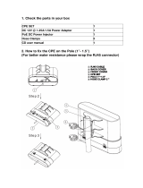
2.2 Package Content
The SoLo51 package contains the following items:
„
One SoLo51 main unit
„
One 18V 1A DC power adapter
„
Passive PoE DC Injector
„
Mounting kits
„
User’s Guide CD
The PoE Ethernet cable is not included in the package. You may choose an outdoor
specification Ethernet cable according to the length you need.
2.3 Optional Accessories
The SoLo51 have the following optional accessories which you can purchase from ALFA
„
Tilting Metal Adjustable antenna degree Pole Mount (Model: L-Mounting Kits):
This kit allows SoLo51 to adjust angle to get perfect connection

2.5 Hardware Installation
1. Plug Power adapter into APoE02-WM
2. Connect RJ45 ( LAN Port ) to computer or Switch
3. Connect RJ45 (PoE Port) to SoLo51

2.5.1
Standard
Pole
Mount
SoLo 51 support vertical and horizontal potions pole mounting.
Please follow the procedure below to install:


2.5.2
Optional SoLo51 Antenna Adjustable Mounting
With Optional Antenna Adjustable Mounting could easy to adjust better angle position to
connect to the Base-Station. Please follow the procedure below to install:

Configuring the SoLo51
Configuring the IP address of your computer
In order to manage with SoLo51, you have to configure the IP addresses of your computer to
be compatible with this device.
Note:
1. The default network setting of the device:
IP address: 10.0.0.1
Subnet Mask: 255.0.0.0
2. In the following TCP/IP configuration guide, the IP address “10.0.0.2 ” is assumed to be
your IP address. Please DO NOT choose 10.0.0.1 for the IP address (10.0.0.1) has
been set as the default IP for this device.
3. The following TCP/IP configuration guide uses windows XP as the presumed operation
system.
Procedures to configure IP addresses for your computer
1. If you are in Classic Start menu view, click StartÆSettingsÆControl PanelÆNetwork
Connections.
If you are in Start menu view, click StartÆControl PanelÆ Network Connections.
2. Double click “Local Area Connection”
3

3. Choose Internet Protocol (TCP/IP) and click Properties.
4. Choose “Use the following IP address” to specify IP addresses manually. Fill in the IP
addresses in each column. Please click the OK button after your configuration.

Starting the WEB-Based Management Interface
The device uses WEB as the management interface. You can use a browser to access the
management interface easily. Please follow up the steps listed below.
1. Double click the Internet WEB browser icon on your desktop screen (Netscape
Communicator 4.0 and Internet Explorer 3.0 or update version)
2. Type 10.0.0.1 into the URL WEB address location and press Enter.
3. The Username and Password Required window appears.
- Enter admin in the User Name location (default value).
- Enter admin in the Password location (default value).
- Click “OK” button

Web Management SoLo51
In this chapter, we will explain about the wireless settings and router mode settings in web
management interface.
With the web management interface, there are 4 basic sections to configure the SoLo51
Start with WISP Wizard: Helps you quickly set up SoLo51 to connect with Base-Station or AP
Start with Home Bridge Wizard: Helps you quickly set up SoLo51 in bridge mode
Start with Home Router Wizard: Helps you quickly set up SoLo51 in router mode
Start with Advanced setup: Provides more detailed configuration options
4

Here will explain all web page functions
In system page
System
Settings
Password Setting
Backup & Restore
Syslog Settings
Firmware Upgrade
Operation Mode:
Bridge: bridge all interfaces together and disabled DHCP server (dnsmasg) & firmwall
Router: NAT and DHCP server enable
To change the password to access the SoLo51 web management
To Download the config. Or Upload the config. Setting file
Remote Syslog:
IP address and port of the remote logging host.
Leave this address blank for no remote logging. The port is set to 514 by default
To upgrade the latest firmware
Time Settings: NTP server to obtain the correct time from the time source and adjust
the local time in each connecting computer
Web Interface setting: allow to change the Language

WAN Page: work on in Router Mode
Bridge Mode doesn’t support WAN setting
LAN Settings:
1. LAN configuration: allow to choose DHCP Client, Static IP or PPPoE
2. IP Settings: are optional for DHCP. They are used as defaults in case the DHCP server is
unavailable.
3. DHCP Service For LAN:
DHCP Start: the start IP address of DHCP server’s IP range. The default value is 100
( valid range: 1~254 )
Max Client Q’ty: the maximum number of DHCP IP. The IP range is from (DHCP start)
to (DHCP start + Max Client Q’ty -1). The default value is 50 (valid range: 1~253)
DHCP Lease Time: DHCP lease time means DHCP server grants permission to a
DHCP client to use a particular IP address. The default value is 1440 minutes (valid
range: 1~86400 minutes)

Wireless 1 Settings:
1. Wireless configuration:
Wlan Mode: AP+WDS Parent: AP master mode.
Client: Wireless client mode for router
WDS child: WDS child mode for bridge
2. Broadcast SSID: broadcast SSID to every clients
3. Transmit power: change the amount of power used by a radio transceiver to send the
signal out.
4. Radio Mode:
b only: only allow 11b clients connection
g only: only allow 11g clients connection
b/g mixed: allow 11b and 11g clients connection
5. Isolation:
VAPs: isolate the traffic between wireless1 and wireless2
Clients: isolate the traffic between each wireless client
6. Distance: please input the distance( meter ) between this device and connection target.
This setting is for long distance connection (>300 meters)
7. Security Mode: WPA2 allows WPA and WPA2 stations.
WPA/WPA2 with RADIUS only support for AP mode

Wireless 2 Settings:
1. Wlan Mode: AP+WDS Parent: AP master mode.
2. Broadcast SSID: broadcast SSID to every clients
3. Transmit power: change the amount of power used by a radio transceiver to send the
signal out.
4. Isolation:
VAPs: isolate the traffic between wireless1 and wireless2
Clients: isolate the traffic between each wireless client
5. Security Mode: WPA2 allows WPA and WPA2 stations.
WPA/WPA2 with RADIUS only support for AP mode
/