Page is loading ...

1
MODERN HOME PRODUCTS GAS GRILLS
Owners Manual
Assembly and Maintenance Instructions
For models JNR, WNK and TJK Series
THIS GAS APPLIANCE IS DESIGNED FOR OUTDOOR USE ONLY.
THESE INSTRUCTIONS SHOULD BE LEFT WITH
THE CUSTOMER. KEEP THESES INSTRUCTIONS
FOR FUTURE REFERENCE.
YOU MUST READ THIS OWNERS
MANUAL BEFORE OPERATING
YOUR GAS GRILL.
FOR YOUR SAFETY
If you smell gas:
1. Shut off gas to appliance.
2. Extinguish any open
flame.
3. Open Lid.
4. If odor continues, imme-
diately call your gas sup-
plier or your fire depart-
ment.
FOR YOUR SAFETY
1. Do not store or use gaso-
line or other flammable
vapors and liquids in the
vicinity of this or any
other appliance.
2. An LP cylinder not con-
nected for use shall not
be stored in the vicinity of
this or any other appli-
ance.
FOR YOUR SAFETY
Follow all leak-test proce-
dures carefully in this man-
ual before using. Do this
even if the grill was dealer
assembled. Do not try to
light this appliance without
reading the “Lighting” in-
structions in this manual.

2
Safety
DANGER
Failure to follow the Dangers, Warnings and Cautions contained in this Owner’s Manual may
result in serious bodily injury or death, or in a fire or an explosion causing damage to property.
WARNINGS
Do not store a spare or disconnected liquid propane cylinder under or near the barbecue.
Improper assembly may be dangerous. Please carefully follow the assembly instructions in this manual.
After a period of storage, and/or nonuse, the MHP Gas Barbecue Grill should be checked for gas leaks and
burner obstructions before use. See instructions in this manual for correct procedures.
Do not operate the MHP Gas Barbecue Grill if there is a gas leak present.
Do not use a flame to check for gas leaks.
Combustible materials should never be within 24 inches of the top, bottom, back or sides of your MHP Gas
Barbecue Grill.
Do not put a barbecue cover or anything flammable on, or in the storage area under the barbecue.
Children should never use your MHP Gas Barbecue Grill. Accessible parts of the barbecue may be very hot.
Keep young children away while it is in use.
You should exercise reasonable care when operating your MHP Gas Barbecue Grill. It will be hot during
cooking or cleaning and should never be left unattended, or moved while in operation.
Should the burners go out while in operation, turn all gas valves off. Open lid and wait five minutes before
attempting to relight, using the lighting instructions.
Do not use charcoal or lava rock in your MHP Gas Barbecue Grill.
Never lean over open grill or place hands or fingers on the front edge of cooking box.
Do not enlarge the valve orifices or burner ports when cleaning the valves or burners.
The MHP Gas Barbecue Grill should be thoroughly cleaned on a regular basis.
Liquid propane gas is not natural gas. The conversion or attempted use of natural gas in a liquid propane
unit or liquid propane gas in a natural gas unit is dangerous and will void your warranty.
Do not attempt to disconnect any gas fitting while your barbecue is in operation.
Use heat-resistant barbecue mitts or gloves when operating barbecue.
LIQUID PROPANE GAS UNITS ONLY
Use the regulator that is supplied with your MHP Gas Barbecue Grill.
Do not attempt to disconnect the gas regulator or any gas fitting while your barbecue is in operation.
A dented or rusty propane cylinder may be hazardous and should be checked by your local liquid propane
supplier. Do not use a liquid propane cylinder with a damaged valve.
Although your liquid propane cylinder may appear to be empty, gas may still be present, and the propane
cylinder should be transported and stored accordingly.
If you see, smell or hear the hiss of escaping gas from the liquid propane cylinder:
1. Move away from the liquid propane cylinder.
2. Do not attempt to correct the problem yourself.
3. Call your fire department.

3
Contents
TABLE OF CONTENTS
Safety (Dangers & Warnings)……………. 2
Warranty……………………………………... 4
General Instructions………………………. 5
Mountings……………………………………. 6 -13
Cart………………………………………………..
6 -7
Deck/Patio……………………………………….. 7-9
In-Ground………………………………………… 9
Optimum Console………………………………. 10 -11
Built-In……………………………………………. 12 -13
JNR/WNK Grill Assembly…………………. 14 -18
TJK Grill Assembly…………………………. 19 - 20
Gas & LP Tank Connections……………… 21 - 22
Leak Testing & Lighting The Grill……….. 23
Maintenance…………………………………. 24 - 26
Annual Maintenance
………………………….
24
General Maintenance
………………………...
24 - 26
26 Tube Bending………………………………..
Troubleshooting……………………………. 27
Parts Information…………………………… 28 - 31
Exclusive, rust-free anodized aluminum
cooking grids. This unique cooking system
heats up faster, reduces flare ups and cooks all
foods at a higher temperature, thereby searing
in the delicious barbeque juices. Wide-ribbed
side for grilling steaks, chops, burgers and ribs,
branding them with sear lines. The flip side, with
its smooth surface is ideal for grilling delicate
foods such as fish, seafood and vegetables.
MHP Grill upgrade options for added
versatility, convenience and cooking enjoyment.
Stainless Steel Side
Burner. The premium
commercial grade
stainless steel side
burner is 11,000 BTU
rated, has its own elec-
tronic ignition, and is fac-
tory assembled for simple
drop-in installation.
Infra-Roast™ Rotisserie
Burner System. Infra-red rear
burner heats up fast to quickly
put a seal around meats for
juicier and more moist results.
Constructed of commercial
grade stainless steel and is
easy to install or remove for
normal grilling.

4
Warranty
MODEL IDENTIFICATION
Your MHP Gas Barbecue Grill is identified by a model number and a serial number located on the left side of the
control panel. Always use both the model and serial numbers when contacting Modern Home Products about your
grill. For future reference, take the time now to record the model and serial numbers below:
MODEL NUMBER:______________________________
SERIAL NUMBER:______________________________
DATE PURCHASED:____________________________
How to contact us: phone: 1-888-647-4745, fax: 1-800-637-2918, or E-mail: [email protected],
or write: Customer Service
Modern Home Products
150 S. Ram Road
Antioch, IL 60002
To validate your warranty, you need to fill out and send in your warranty card within 10 days. You can either
mail or Fax it to us. Or you can fill out the warranty card at our website: www.modernhomeproducts.com.
LIMITED WARRANTY
Modern Home Products Corp. Offers to the original purchaser a Limited Warranty on all aluminum grill components
except the 7 year “SearMagic” cooking system. These components will be free from defects in material and workmanship
(excluding paint) when subject to normal domestic use and service. The highest quality paint is used where applicable,
but due to various atmosphere conditions, chemicals, fertilizers, care, cleaning and actual use, no extended warranty can
be made on paint. Also, for these reasons the limited warranty does not cover rust or aluminum oxidation, unless there is
a loss of structural integrity on the grill components.
The Stainless Steel Burner is covered for a period of 7 years, Porcelain Briquettes 5 years, all other grill components
for 1 year.
Warranty coverage begins on the original date of purchase, confirmed by return registration card and bill of sale.
Proof of purchase is required to validate warranty.
Any component that proves defective within the warranty period will, if returned to the factory freight prepaid, be re-
paired or replaced free of charge. Warranties shall not apply, nor will M.H.P. assume responsibility for damages that
might result from failure to follow M.H.P.’s instructions, local codes, or when the grill has been tampered with, or altered
in any way. M.H.P. shall not be liable for any transportation charges, labor costs, or export duties.
Repair or replacement of a M.H.P. gas grill part does not extend the limited warranty beyond its original term from
date of purchase, or begin a new limited warranty period.
This warranty does not include the cost of any inconvenience or property damage due to the failure of the product
and does not cover damage due to misuse, abuse, accident, damage arising out of transportation of the product, or dam-
age incurred through commercial use of the products. This express warranty is the sole warranty given by the manufac-
turer and is in lieu of all other warranties, expressed or implied, including implied warranty of merchantability or fitness for
a particular purpose.
ALL WARANTIES are null & void if grills are put into
commercial or community use such as by hotels,
condominium associations, apartment committees,
etc.
Date Warranty Registration Was Mailed___________
MODERN HOME PRODUCTS CORP.
150 S. RAM ROAD
Antioch, IL 60002
—————————————————————
MODERN HOME
P R O D U C T S
—————————————————————–

5
GENERAL INSTRUCTIONS
This installation guide provides you with easy to fol-
low illustrations and instructions to assemble your
MHP Gas Barbecue Grill.
Before you start assembling and using your MHP
Gas Barbecue Grill we recommend that you read
through all precautions, safe guards and instruc-
tions to avoid any personal injury or property
damage.
Check Local Codes. Contact your local LP dealer or
Natural Gas company for recommended installation
procedures and regulations. If there are no local
codes, installation must conform to the latest National
Fuel Gas Code: ANSI Z 223.1. For Canada, installa-
tion must comply with local codes and/or Standard
CAN/CGA-B-149-1 for natural gas installation and
CAN/CGA- B-149-2 for propane installation.
For LP Gas Models the supplied Gaslow GS-801
Regulator must be used. Any replacement pressure
regulator or hose assembly must meet or exceed the
specifications of the Gaslow GS-801 Regulator.
For Natural Gas Models the grill is designed to oper-
ate at a pressure of 7” water column (W.C.) (1.75
kPa). Check your gas utility for local pressure. Pres-
sures other than approximately 7” W.C. could affect
the performance of your grill.
ASSEMBLY INSTRUCTIONS
There are 9 steps to assembling your MHP Gas Bar-
becue Grill: The mounting, LP tank mounting, control
panel, gas supply connection, grill lid, lid handle, side
shelves, and rock grate, cooking grid and warming
rack.
The grill itself is partially assembled with the Burner,
Venturis, Ignitor Collector Box and the Gaslow Regu-
lator installed.
The JNR and WNK grills are specifically designed to
fit the five mounting methods: Cart, In-Ground Post,
Deck/Patio Base, Optimum Console and Built-in. The
TJK Grill is supported by the Optimum Console
mounting and Built-in.
You will need the following tools to assemble
your grill:
• A Phillips head screwdriver
• A standard flat head screwdriver
• Two 7/16” wrenches or sockets
STORAGE
Turn gas OFF at the LP cylinder (or at the shut OFF
valve in the case of Natural Gas) when the MHP Gas
Barbecue Grill is not in use.
Do not store spare LP cylinders under the MHP Gas
Barbecue Grill.
Store disconnected LP cylinders outdoors in a well-
ventilated area, do not store in shed, building, garage
or in any enclosed area.
Do not install your MHP Gas Barbecue Grill
in or on recreational vehicles and/or boats.
Never use your MHP Gas Barbecue Grill near
combustible surfaces, including roof over-
hangs, roofs, vinyl siding and window shut-
ters. Maintain at least a 6-foot clearance.
Use this barbecue outdoors in a well-
ventilated area.
Do not use your MHP Gas Barbecue Grill in a
shed, garage, building, breezeway or any
other confined area.
Do not use any kind of combustible material
on or near the top, bottom, back or sides of
the grill. Maintain at least a 2-foot clearance.
Leak test all gas supply line connections.
Do not let children operate a gas grill.
Keep the area around the grill clear of com-
bustible vapors or liquids such as gasoline.
When operating the grill do not leave unat-
tended. Keep children and pets away.
Keep fuel supply hose and electrical supply
cord away from any heated surface.
OPERATING SAFEGUARDS
General Instructions
SAFETY
YOUR GRILL IS DESIGNED FOR OUTDOOR USE ONLY.
It should also not be used in an enclosed area such as a shed
or garage because combustion uses available oxygen and dis-
charges carbon monoxide.
The grill must be located no closer than 24" from any combus-
tible surface behind or to the sides. Grill should not be located
under overhead unprotected combustible surfaces.
Keep the area around the grill clear of combustible materials,
flammable vapors or liquids such as gasoline.
Do not obstruct the flow of combustion and ventilation air.

6
Mountings
Complete view of Cart Assembly
Step 1: Leg Assembly
(Fig. 2)
1. Tip the grill head bottom on end as shown in Fig. 2.
(TIP: work on protected area such as: carpet, tarp or
one of the boxes to protect cart finish.)
2. Attach the two short legs to the left end of the grill
head bottom with the “Hose Ring Hole” leg facing
grill front. Use two ¼-20 x 1½" slotted bolts for each
leg. Insert bolts from inside grill box, attach leg and
fasten with ¼-20 Kep nuts.
3. Attach the two long legs to the right end of the grill
head bottom. Use two ¼-20 x 1½" slotted bolts for
each leg. Insert bolts from inside grill box, attach leg
and fasten with ¼-20 Kep nuts.
4. Attached the hose clamp ring to the front left short
leg with the 10 x 24 x ½" Rd. Hd. slotted bolt.
FINGER TIGHTEN ALL BOLTS UNTIL
LOWER SHELF IS ATTACHED.
Cart Mounting carton contains the following
components:
Please check to be sure that all parts are included be-
fore proceeding. Contact your dealer if any parts are
missing.
Parts
Quantity
Long Legs 2
Short Legs 2
Lower Shelf Frame 1
Stainless Grease Cup 1
Grease Cup Holder 1
8” Rubber Wheels 2
Axle Hitch Pins 2
Axle Washers 2
Hub Caps 2
Hose Retaining Ring 1
LP Tank Holder Ring Assembly 1 (Propane Models Only)
Hardware Kit
¼-20 x 1 ½" Rd. Hd. Sltd. Bolts 11
¼-20 Kep Nuts 15
10-24 x ½" Rd. Hd. Sltd. Bolt 1
10-24 x ½" Hex Kep Nut 1
¼-20 Thumb Sc 1 (Propane Cart Only)
¼-20 x ¾" Hex Head Bolt 1 (Propane Cart Only)
12’ Natural Gas Hose 1 (Nat. Gas Cart Only)
Brass Quick-Disconnect 1 (Nat. Gas Cart Only)
Quick-Disconnect Dust Plug 1 (Nat. Gas Cart Only)
Dust Cap 1 (Nat. Gas Cart Only)
Cart Assembly Instructions
(JCP, JCN, WCP & WCN)
Step 2: Lower Shelf Assembly
(Fig. 3)
1. Slip the lower shelf axle through the holes in the
short legs.
2. Slide the wheels on the axle ends, then a washer
on each, followed by a hitch pin clip through the
axle hole. Tap plastic hub cap lightly to secure
tight.
3. Align the other end of the lower shelf with the holes
in the long legs. For the JNR model, slip the axle
through the holes and fasten both ends with the
threaded ¼-20 x ¾" slotted Rd. Hd. head bolt. For
WNK model, use two ¼-20 x 1½" bolts and Kep
nuts to fasten the lower shelf to the long legs (see
Fig 3 inset).
STAND GRILL UPRIGHT TO SEAT LEGS AND
TIGHTEN ALL BOLTS AND NUTS MAKING THE LEGS &
FRAME RIGID. PERIODICALLY CHECK ALL
FASTENERS FOR TIGHTNESS.

7
Mountings
For Natural Gas Models
(
Note: Tank Holder Ring is not included with natural
gas models.)
If the grill is to use natural gas from the supplied 12-
foot hose: the hose must pass through the hose
clamp (See Fig. 1). The hose will have a quick-
disconnect fitting at the source and the source will
have a gas shut off valve with easy access.
Step 3: Tank Holder Ring Assembly For LP
Gas Models
(Fig. 4)
1. The L.P. Tank Holder Ring Connects to the lower
shelf cross frame with the ring notches resting on
the axle frame.
2. Align the rear tank ring-fitting hole over the lower
cross frame hole. Insert a ¼ - 20 x
5/8"
slotted bolt
through the top and fasten with a ¼ - Kep nut
from below.
3. Fasten the thumb screw (¼- 20 x ¾") to the tank
ring fitting with the ¼ - 20 Hex nuts. The Hex nut
slips into the captive slot on the tank ring fitting.
4. Use a ¼ - 20 x 1½" slotted bolt and a ¼ - 20 Kep
nut to connect the tank holder flanges together.
Deck/Patio Mounting
Assembly Instructions (MPB)
• Either the JNR or WNK model grills may be
mounted on the Deck/Patio base.
• The gas supply may be either LP or Natural.
• The grill head bottom should not be attached
to the post until the mount is fasten to a
deck/patio.
Please check to be sure that all parts are included
before proceeding. Contact your dealer if any parts
are missing.
Parts Quantity
2' Post 1
Patio Base 1
Post Access Door 1
Grease Cup Holder 1
28” Stainless Steel Tubing 1
Stainless Steel Grease Cup 1
Hardware Kit
¼ - 20 x ¾" Hex Head Bolts 7
¼ - 20 Kep Nuts 7
¼" Flat Washers 7
8 - 32 x ½" Self Tapping Screw 1
Tube Clip 1
When you have completed the mount assembly
go to the appropriate Grill Assembly Section and
assemble the grill head.
Continue on following page. !
!!
!
Caution: Combustible material should never be
within 24 inches of the top, bottom, back or
sides of your MHP Gas Barbecue Grill.
Fig. 3

8
Mountings
Step 1: Patio Base Mounting Assembly
(Fig. 5)
1. Turn base on edge and insert the 2’ post. Align the
notches in the post with the notches in the base. IM-
PORTANT: Close tolerances may require you to tap
the top of the post to seat it completely in the base
socket which will then align the bolt slots.
2. Fasten post to base with four ¼ - 20 x ¾" Hex bolts,
washers and Kep nuts. Follow exact placement of
washers as indicated. Tighten securely.
3. Attach the tube clip with the 8 - 32 self-tapping screw
either on the right or left side of the base depending
on the direction of your gas supply line.
Step 2: Deck/Patio Mounting Installation
(Fig. 6)
Position the patio base at the desired location on a
deck or patio. CAUTION: Be certain there are no
combustible materials above, behind, left or right
closer than 24" away.
1. Mark the location of the four holes at the outside
corners of the patio base and drill four holes. The
base will be fastened down with lag bolts (not sup-
plied by MHP) after you have connected the gas
supply line. The top post notch is the front and the
rear access door will be in the back of the grill.
2. Run the gas supply line into the post from the bot-
tom to reach the access door and bend it 90° to
exit the base at either notch. The patio base is
notched on two sides to allow the gas line to exit
either right or left.
3. Secure the gas line with the tube clip. (Option: On a
raised deck if the gas supply line is to be run straight
up into the post from below use the tube clip to attach
the gas line to the deck for support.
4. At the access door connect a 3/8" flare coupling (not
supplied by MHP) to the gas supply line and Stainless
Steel tubing. Position the tubing in the top notch of the
post. Bend the tubing at the top end to match the Feed
Line of the grill valve. Do not kink the tubing.
TUBE BENDING: For proper bending of the stainless steel
tubing, see page 26 for bending instructions.
Step 3: Attaching The Grill Head Bottom To The
Deck/Patio Post
(Fig. 7 & Fig. 8)
1. To make the post-to-flange connection easier, re-
move the grill burner by taking out the small clip lo-
cated under the bottom grill head. This will allow ac-
cess to hold the Kep nuts inside the post.
2. Set the grill head bottom carefully in place, align
holes and use the ¼ - 20 x ¾" bolts and ¼-20 Kep
nuts to attach the grill flange to the post.

9
Mountings
In-Ground Mounting
Assembly Instructions (MPP)
• Either the JNR or WNK model grills may be
mounted on the In-Ground Mounting base.
• The gas supply may be either LP or Natural.
• To protect against corrosion, you must apply
a suitable coating on the post to retard the
effects of corrosion existing in local areas.
• The grill head should not be attached to the
post until the post is permanently cemented
in ground.
Please check to be sure that all parts are included be-
fore proceeding. Contact your dealer if any parts are
missing.
Parts Quantity
4' Post 1
Post access door 1
28” Stainless Steel Tubing 1
Stainless Steel Grease Cup 1
Stainless Grease Cup Holder 1
¼ - 20 x ¾" Hex Head Bolts 3
¼ - 20 Kep Nuts 3
Step 1: In-Ground Mounting Installation
(Fig. 9)
1. Dig a posthole about 8 inches wide by 2 feet
deep. Caution: Locate the hole so that the
mounted grill head has a clearance of 24
inches away from any combustible object or
surface; above, back, left or right.
Center the post in the hole and plumb it. Pour in
When you complete the mount assembly go to
the appropriate Grill Assembly Section and as-
semble the grill head.
cement (gravel) up to the gas line access hole.
Keep in mind that the gas line access hole is on
the back of the post and the notch at the top if fac-
ing front. Recheck plumb and allow cement to set.
2. Run the gas supply line into the post access hole
(just above the cement). Make a 90° bend to reach
the access door opening.
The gas supply line should be trenched at least 18
inches below the surface of the ground to prevent
damage from digging. CAUTION: The gas supply
line must be regulated (in the case of natural
gas that means connected after your gas meter
and regulator) and that you have an easily ac-
cessible shut-off valve.
3. At the access door connect a 3/8" flare coupling
(not supplied by MHP) to the gas supply line and
Stainless Steel tubing. Position the tubing in the top
notch of the post. Bend the tubing at the top end to
match the Feed Line of the grill valve. Do not kink
the tubing.
Step 2: Attaching The Grill Head Bottom To
The In-Ground Post
(Fig. 7 & 8)
To attach the grill head to the post please refer to Step
3 of the Deck/Patio installation procedures on page 8
and follow instructions.
When you complete the mount assembly Go to the
appropriate Grill head section and assemble the
Grill Head.
TUBE BENDING: For proper bending of the stainless steel
tubing, see page 26 (Fig. 47) for bending instructions.
3. Mount the grease cup holder to the rear flange hole
with a ¼ - 20 x ¾" bolt and ¼-20 Kep nut. The
grease cup holder is supplied with the grill head.

10
Mountings
Stainless Steel Optimum Console
Assembly Instructions
• The JNR, WNK or TJK model grills may be
mounted on the Optimum Console.
• The gas supply may be either LP or
Natural.
• The grill head should not be attached to the
Optimum Console until the console is
completely assembled
• The Optimum Console comes in two car-
tons—Box A contains the console and all
associated hardware. Box B contains either
the pedestal or cart base and all base
hardware.
Please check to be sure that all parts are included
before proceeding. Contact your dealer if any parts are
missing.
Parts Quantity
BOX A
Stainless Steel Front Panel 1
Stainless Steel Console 1
Stainless Grease Cup 1
Tank Lock Bar 1
Hardware Kit
Nylon Lock Bar Spacers 2
¼ - 20x1¼" S.S. Hex Head Bolts 4
¼ - 20 S.S. KEP Nuts 12
¼ S. S. Washers 10
¼ - 20 x ¾" S.S. Hex Bolts 8
Rectangular Washers 4
2-piece Gasket 1
BOX B
Cast Aluminum Base 1
12’ Nat. Gas Hose/Quick Discount 1
(Cart Nat.
Gas Only)
Stainless Steel Flexible Tubing, 28”
1
(Pedestal Nat.
Gas Only)
Axle 1
(Cart Only
)
Axle Clips 2 (
Cart Only)
6 " Wheels 2
(Cart Only)
Hub Caps 2
(Cart Only)
Step 1: Connect the Tank Locking Bar
(Fig. 10)
1. From box “A” locate and attach the Tank Lock Bar
across the back of the pedestal column. Use the ¾"
S.S. Hex bolt, Nylon Lock Bar Spacer and a Kep nut
on each side to fasten the Tank Lock Bar in place.
This spreads and holds the correct spacing at the
back of the column.
Step 2: Attach the Base to the Pedestal
(Fig. 11)
1. Before bolting the pedestal column to the base, the
2-piece gasket must be installed to create a barrier
between the two metals. Remove the backing strips
from the gasket to expose the adhesive and stick
the gasket to the bottom lip of the pedestal column.
Make sure to align the holes.
2. Attaching the pedestal column to the base will be
easier to handle by laying the pedestal column face
down and matching the holes on the pedestal col-
umn lip to the holes on the base. Use six ¾” bolts,
four large rectangular washers, and on the under-
side six round washers and KEP nuts.
IMPORTANT: the large rectangular washers are
used at the sides on top of the pedestal column lip.
The round washers and KEP nuts are used under
the base. Tighten securely and stand unit upright.
Note: While assembling, peel the thin white protective film
covering the stainless steel surfaces, especially in areas
which will be partially hidden after assembled. Do Not
Scrape off.

11
Mountings
OPTION: For OPTIMUM Cart Only:
(Fig. 12)
1. Attach the wheels by slipping the axle through the
base, slide the wheels on and secure with the axle
clips. Finish by snapping the hub caps on before
standing unit upright.
Step 3: Connect the Grill Head Bottom
(Fig. 13)
1
.
Attach the grill head bottom to the pedestal column
top with four ¼ - 20 x1 ½" Hex bolts, washers under
the bolt head and Kep nuts. Peel the remaining
protective coating off the pedestal column.
When you complete the mount assembly go to the
appropriate Grill Assembly Section and assemble
the grill head.
Step 4: Attaching the Access Panel
(Fig. 14)
Note: Do not attach the front access panel until
the control panel has been attached to the
grill head bottom and the gas supply line
has been properly connected and leak
tested.
1.
The front access panel attaches directly under the
control panel and hides the access opening. Lift
the access panel up behind the lip of the control
panel, then slip the bottom double edge of the ac-
cess panel (upward pressure may be needed) over
the edge of the access opening.
Caution: Combustible material should never be
within 24 inches of the top, bottom, back or sides
of your MHP Gas Barbecue Grill.

12
Mountings
Built-in Kit Mounting
Assembly Instructions (NMS)
• The JNR, WNK or TJK model grills may be
mounted as a built-in.
• For use with natural or hard–plumbed propane
gas.
• Use of the Built-in kit for LPG poses a safety
risk and voids any and all warranty.
• Enclosure must be constructed from non com-
bustible materials.
• The Built-In kit and grill head connection will
be assembled upside down.
• Refer to appropriate section for grill head as-
sembly.
Please check to be sure that all parts are included be-
fore proceeding. Contact your dealer if any parts are
missing.
Parts Quantity
Set of doors with magnetic catches
Consisting of:
Frame for Door Set 1
Left Hand Door 1
Right Hand Door 1
Heat Shield 1
Magnetic Catches 2
Door Handles 2
Front Face Plate for NMS (
26" W x 11" H x 1½" D)
1
Right Side “L” Bracket 19" x 11" 1
Left Side “L” Bracket 19" x 11" 1
Rear Support Bracket 26
1/8
" long 1
Grease Tray 1
Hardware Kit
¼ - 20 x ¾" Hex lts 12
¼ - 20 x 1 ¼" Hex Bolts 4
¼" Nuts 4
¼" Flat Washers 4
¼" Lock Washers 16
Important Notes:
Your structure should have a 3" to 4" concrete base on a
sand footing.
The panel doors must have a 4" to 6" minimum elevation
from the ground.
If your structure includes a back splash, allow 11" to the
back edge of grill opening to allow the lid to open com-
pletely.
Combustible material should never be within 24 inches of
the top, bottom, back or sides of your Grill
.
Complete View Of Built-In
Step 1: Required Dimensions For Built-In
(Fig. 16)
1. The grill head fits into an opening of 27½" wide by
10¾" high by 18" deep.
2. The Panel doors fit into an opening of 27¼" wide by
16¾" tall.
3. The side burner fits a surface opening of 10¼" wide
by 11¾" front to back. It should be at least 5" away
from the grill opening.
(The front face flanges on the mounting and the panel
doors overlap the required opening surfaces by 1
5/8
"
and provide a clean look.)
12

13
Mountings
Step 2: Built-In Mounting Assembly
IMPORTANT: Since the mounting is attached directly
to the grill, you must first partially assemble your grill
by attaching the control panel to the grill head (refer to
the appropriate grill section for assembly instructions).
Then the built-in mounting heat shield must be at-
tached to the bottom of the grill head using four ¼-20 x
¾" bolts, see fig. 14 “Complete View” illustration.
Do not forget to remove the protective film from all
stainless steel parts of your built-in mount.
To assemble the built-in frame
(Fig. 17)
1. Align the holes of the right hand “L” bracket with the
face panel (the face panel’s 12 vent slots should be
on the top) and insert two 1/4 x ¾" Hex bolts and
fasten with flat washer, lock washer and nut, do not
tighten at this time. When properly connected the
grill support tabs on the “L” bracket should be facing
up and inward.
2. Repeat procedure to connect the left hand “L”
bracket.
3. Attach the rear bracket to both the right and left “L”
brackets using two ¼ - 20 x ¾" Hex bolts at each
end. Secure bolts with a flat washer, lock washer
and nut.
4. Attach the frame to the bottom grill head by aligning
the frame support tabs with the grill head bottom
holes. Insert the ¼ - 20 x 1 ¼" Hex bolt from inside
the grill head and screw it into the threaded frame
support tab.
To connect the full assembly to the enclosure.
5. Slide the grill head into the opening 3/4 of the way
in. Connect the gas supply using an approved out-
door connector. Check for gas leaks. (See Gas
Leaks page 23.)
Note: Be certain that the gas pressure is
between 6.5" and 7.5" water column. Excess
gas pressure can cause warping and damage to
grill head.
6. When finished connecting gas supply, slide grill all
the way into to opening so that the “L” bracket face
flanges fit snuggly to your enclosure face. Drill a
hole in the masonry to match up with the “L” bracket
face flange holes and fasten with lag bolts (not
supplied).
Do not build a shelf below the bottom of the
grill. The grill requires an open area for proper
ventilation and service access.
7. Install the pre-assembled door kit by securing with a
suitable fastening method. (Anchors and/or screws
not included.)
When you complete the mount assembly go to
the appropriate Grill Assembly Section and fin-
ish assembling the grill head.

14
JNR & WNK Assembly Instructions
CARTON CONTENTS
MODEL JNR GRILL
Parts
Quantity
Top Casting (Grill Lid) 1
Bottom Casting (Grill Head) 1
Sta-Kool Handle 1
Handle End Caps 2
Warming Rack 1
Bottom Grate 1
Porcelain Cooking Grids 1 (SearMagic 2)
Control Panel Brackets 2
Heat Shield 1
Grease Cup Holder 1
Control Panel Assembly 1
Valve Control Knobs 2
Ignitor Knob 1
Side Shelf 1
Side Shelf Bracket 1
Venturi Tube Cleaning Brush 1
Bag of Briquettes (53 pieces) 1
Meat Probe 1
Forked Grid Cleaning Tool 1 (SearMagic Only)
Hardware Quantity
Connecting Wire for Ignitor 1
¼-20 x 1½" Rd. Hd. Sltd. Bolt 4
¼-20 x ½" Rd. Hd. Sltd. Bolt 2
¼-20 x ¾" Hex head Bolts 3
¼-20 x 1" Hex head Bolts 4
¼-20 x 1½" Hex Head Bolt 2
¼-20 KEP Nut 11
Keeper Washer 2
Graphite Washer 2
Flat Washer for Ignitor 1
1/8-27 Jam Connecting Nut 1
Lid Pivot Pin 2
Hitch Pin for Lid 2
MODEL WNK GRILL
Parts Quantity
Top Casting (Grill Lid) 1
Bottom Casting (Grill Head) 1
Sta-Kool Handle 1
Handle End Caps 2
Warming Rack 1
Bottom Grate 1
Stainless Steel Cooking Grids 2 (SearMagic 3)
Control Panel Brackets 2
Heat Shield 1
Grease Cup Holder 1
Control Panel Assembly 1
Valve Control Knobs 2
Ignitor Knob 2
Side Shelf 2
Side Shelf Bracket 2
Venturi Tube Cleaning Brush 1
Bag of Briquettes (63 Pieces) 1
Meat Probe 1
Forked Grid Cleaning Tool 1 (SearMagic Only)
Hardware Kit Quantity
Connecting Wire for Ignitor 1
¼-20 x 1½" Rd. Hd. Sltd. Bolt 6
¼-20 x ½" Rd. Hd. Sltd. Bolt 2
¼-20 x ¾" Hex head Bolts 3
¼-20 x 1" Hex head Bolts 8
¼-20 x 1½" Hex Head Bolt 2
¼-20 KEP Nut 13
Keeper Washer 2
Graphite Washer 2
Flat Washer for Ignitor 1
1/8-27 Jam Connecting Nut 1
Lid Pivot Pin 2
Hitch Pin for Lid 2
Please check to be sure that all parts are included before proceeding with assembly. Contact your local dealer
if any parts are missing.
Note: The grill is partially assembled. The Burner, Spider Guards, Venturis, Ignitor Collector
Box are installed. Also, for LP units the Gaslow Regulator and Hose are installed.

15
JNR & WNK Assembly Instructions
Grill Head Assembly
Instructions
• The grill head bottom must be attached to
the mounting before starting.
• It is easiest to work with the grill in the up-
right position.
• The difference between the JNR and the
WNK is the WNK is larger, has two side
shelves and the warming rack fastens dif-
ferently.
• Leak test all gas connections before
using.
• Caution: Combustible material should
never be within 24 inches of the top, bot-
tom, back or sides of your MHP Gas Bar-
becue Grill.
View of JNR & WNK Grill Head Components
Step 1: Control Panel & Heat Shield
A.
Attaching Heat Shield and Control Panel
(Fig. 19)
1. Insert the ¼ - 20 x ¾" Hex bolts through the two
holes in the front of control panel.
2. Press a keeper washer to hold the bolts in place.
3. Slip the control panel shield onto the bolts.
4. Attach the complete control panel assembly to the
front of the grill head with a ¼ - 20 Kep nut.
5. Make sure the valve orifices on the control panel
aligns with the burner venturi correctly and that the
venturi tubes go over the valve orifices at least ¼" to
½" (see fig. 22 on page 16).
B. Connecting the Control Panel Support Brackets
(Fig. 20)
1. Two support brackets are connected beneath the
control panel to the grill head for added support.
Push a ¼ - 20 x 1¼" Phillips head bolt through the
grill head from the inside.
2. Slip the support bracket in position, fasten with a
¼ - 20 Kep nut.
3. Attach the control panel to the support bracket by
pushing up a ¼ - 20 x ½" Phillips head bolt through
the support bracket and through the lower lip of the
control panel, fasten with a ¼ - 20 Kep nut.

16
JNR & WNK Assembly Instructions
C. Ignitor Wire Connection
(Fig. 21)
1. Tip the grill on its back (or upside down) and attach
the control panel ignitor wire to the terminal stick-
ing out from the bottom of the grill. Be careful not
to crack the delicate porcelain insulator.
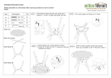
D. Orifice Engagement
(Fig. 22)
At the top end of each valve there is a tiny gas open-
ing known as the orifice. Gas exits the orifice and
enters a venturi where it mixes with air coming in from
the side air shutter. The proper mixture of air and gas
produces a clean blue flame at the burner.
Make sure the valve orifice on the control panel aligns
with the burner venturi tube correctly. The orifice
should fit into the venturi tube ¼" to ½" inches as
shown below.
WARNING! Always check the alignment of the orifice
and the venturi whenever the grill has been moved.
Make sure that the orifice fits into the venturi tube
1/4" to 1/2". Failure to make this connection may
cause fire and result in serious body injury or dam-
age to your grill.
Step 2: Connect the gas supply line
(Fig. 23)
A. For LP-Gas Tank and LP Cart Models:
1. Pass the Gaslow Regulator Hose through the
hose clamp ring and screw the ring to the front of
the left leg.
2. Connect the regulator end of the hose to the LP-
Gas Tank. Tighten securely and leak test both
connections. See Leak Testing on page 23.
B. For Natural Gas Cart, Deck/Patio and In-
Ground Mounts Using 12 foot Hose:
Connect one end of the supplied 12 foot hose to the
grill valve connection behind the control panel. Then,
connect the quick disconnect valve on the hose to the
gas supply line connection. Tighten securely and
leak test both connections. See Leak Testing on
page 23.
Do not al-
low the
gas hose
to come in
contact
with the
bottom of
the grill
head.
C. For Deck/Patio & In-Ground Mounts Using 30"
Flexible tubing.
(Fig. 24)
Connect the 30" flexible tube to the incoming gas
supply using a 3/8" flare coupling (not supplied). At-
tach the other end to the grill valve connection behind
the control panel. To tighten securely use two
wrenches. Hold valve joint with one wrench and
tighten the hose fitting with second wrench. After
Tighten leak test both connections. See Leak
Testing on page 23.
Do not use compound
or Teflon tape on flare
fittings.

17
Natural gas hose for Optimum cart mount:
The natural gas cart
uses a 12 foot hose with
a quick disconnect
(supplied). The hose
passes beneath the heat
shield through the front
access opening and
connects directly to the
control valve. The quick
disconnect end attaches
to the gas supply line at
the shut-off valve.
(Fig. 28)
JNR & WNK Assembly Instructions
Step 2: Continued
D. Optimum Console Mount Gas Connections
All Optimum Console mounts:
The supply line connection pass beneath the heat
shield and through the
front slot with the pro-
tected edge and at-
taches to the valve.
Don’t forget to attach the
front Access Panel to
the Optimum Console.
(Fig. 25)
LP Propane for Optimum cart and pedestal
mounts:
The hose connection
from the Gaslow/
Regulator passes out the
front access opening;
resting on the protected
slot edge beneath the
control panel. The LP
tank locking bar will
press against the tank as
it is lowered into place to
prevent tank movement.
(Fig. 26)
Natural gas for Optimum pedestal mount:
The gas line enters at the rear of the base curving up
through the base opening.
The stainless steel flexible
tubing line must be con-
nected to the incoming gas
line using a
3/8
" flare cou-
pling (not supplied by
MHP). The flexible tubing
then passes beneath the
heat shield and through
the front access opening
and attaches to the control
valve. (Fig. 27)
See page 26 for tubing
bending instructions.
Step 3: Attaching the Side Shelf
(Fig. 29)
1. Turn NuStone Shelf upside down, noting the hole
location of the (2) Brass Treaded Inserts.
2. Lay Aluminum side shelf bracket onto shelf and
mount NuStone Shelf with supplied ¼-20 x 1¼"
Phillips head bolt and Lock washers. Do not
over tighten.
3. Attach the entire unit to the grill head by inserting
two ¼-20 x 1½" Rd. Hd. Sltd screws. Insert bolt
through the holes located on either the right or left
side of the bottom grill head, fasten with a ¼-20
Kep nut.
(Note: Repeat steps 1 and 3 to attach the WNK
model second side shelf.)
Tighten all gas connections securely and leak test
both ends. See Leak Testing on page 23.

18
JNR & WNK Assembly Instructions
Step 4: Attaching the Grill Lid
(Fig. 30)
1. Attach the grill lid to the grill head bottom using the
two Hinge Pins and Hinge Clips.
Step 5: Connect the Handle
(Fig. 31)
1. Attach the handle to the grill lid using two ¼ - 20 x 1
½" Hex bolts with Kep nuts. Graphite Gaskets are
positioned between the end caps and grill lid as
shown in fig. 31.
Use two 7/16" wrenches, one to hold the bolt head
and one to tighten the nut.
Step 6: Grates, Briquettes and Cooking Grids
(Fig. 32)
1. Place the one piece Briquette Grate on the shelf
edge just above the burner.
2. Carefully place the Ceramic Briquettes on the grate
in the pattern shown. Use only one layer.
3. Place the two Cooking Grids above the Briquette
Grate.
Step 7: Warming Rack
1. The JNR
Warming Rack
rests in the
notches on the
top edge of the
grill head bot-
tom.
(Fig. 33)
2. The WNK swingawayWarming Rack connects to the
grill lid and the
grill head bot-
tom. First, insert
the right Top
and Bottom
Rods into their
respective
mounting holes
on right side of
the grill lid and grill head bottom. Then slide the
RACK to your left, positioning the left Top and Bottom
Rods into their respective mounting holes simultane-
ously. The Lower Right Rod End can then be
“popped” into place by flexing it inward.
(Fig. 34)
Before using your grill, leak test all gas line
connections. And follow the lighting instruc-
tions. See page 23.
3. The SearMagic Warming
Rack drops onto the top
edge of the grill head
bottom. the warming rack
bracket is positioned be-
tween the hinges of the
grill head bottom inside
back wall.
(Fig. 35)

19
TJK Assembly Instructions
MODEL TJK Grill
Parts Quantity
Top Lid Assembly 1
Bottom Casting (Grill Head) 1
Warming Rack 1
Bottom Grate 1
Stainless Steel Cooking Grids 2 (SearMagic 3)
Control Panel Brackets 2
Heat Shield 1
Grease Cup Holder 1
Control Panel Assembly 1
Valve Control Knobs 2
Ignitor Knob 2
Stainless Steel Side Shelf 2
Side Shelf Bracket 2
Condiment Holder 2
Venturi Tube Cleaning Brush 1
Bag of Briquettes (67 pieces) 1
Meat Probe 1
Forked Grid Cleaning Tool 1 (SearMagic Only)
Hardware Quantity
Connecting Wire for Ignitor 1
¼-20 x 1½” Rd. Hd. Sltd. Bolt 2
¼-20 x 1¼” Rd. Hd. Sltd. Bolt 4
10-24 x 1¼” Rd. Hd. Bolt 8
¼-20 x ¾” Hex Head Bolt 3
¼-20 x ½” Rd. Hd. Sltd. Bolt 2
10-24 KEP Nut 8
¼-20 KEP Nut 11
Keeper Washer 2
Flat Washer for Ignitor 1
1/8 – 27 Jam Connecting Nut 1
Lid Pivot Pin 2
Hitch Pin for Lid 2
CARTON CONTENTS
Please check to be sure that all parts are included before proceeding with assembly. Contact your local dealer
if any parts are missing.
Note: The grill is partially assembled. The Burner, Spider Guards, Venturis, Ignitor Collector
Box and the Stainless Steel Handle are installed. Also, for LP units the Gaslow Regulator and
Hose are installed.

20
TJK Assembly Instructions
Grill Head Assembly
Instructions
• The grill head bottom must be attached to
the mount before starting.
• It is easiest to work with the grill in the
upright position.
• Leak test all gas connections before using.
• Caution: Combustible material should never
be within 24 inches of the top, bottom, back
or sides of your MHP Gas Barbecue Grill.
Complete View of TJK Grill
IMPORTANT: Most of the TJK Model major
component assembly is the same as the JNR/
WNK Models. Please refer to the JNR/WNK
assembly instructions as indicated.
Step 1: Control Panel & Heat Shield
(See JNR/WNK instructions on page 15, Fig. 19 & 20)
Step 2: Connect The Gas Supply Line
(See JNR/WNK instructions, item D on page 17, Figs.
25-28)
Step 3: Attaching the TJK Side Shelf
(Fig. 37)
1. Fasten the Shelf Bracket to the Right side of grill
head bottom with two ¼-20 x 1¼" Rd. Hd. Sltd
bolts and ¼-20 Kep nuts.
2. Attach the Shelf and the Condiment Holder to the
Brackets. All four 10-24 x 1¼" bolts should be in-
serted into the bracket before tightening them with
10-24 Kep nuts..
(Note: Repeat steps 1 and 2 to attach the other
side shelf.)
Step 4: Attaching the Grill Lid
(See JNR/WNK instructions on page 18, Fig 30.)
Step 5: Grates, Briquettes and Cooking Grids
(See JNR/WNK instructions on page 18, Fig. 32)
Step 6: Warming Rack
(Fig. 38 & 39 )
1. The Warming Rack connects to the grill lid and the
grill head bottom. First, insert the right Top and Bot-
tom Rods into their respective mounting holes on
right side of the grill lid and grill head bottom. Then
slide the RACK to your left, positioning the left Top
and Bottom Rods into their respective mounting holes
simultaneously. The Lower Right Rod End can then
be “popped” into place by flexing it inward.
Before using your grill, leak test all gas line
connections. And follow the lighting in-
structions. See page 23.
2. The SearMagic Warming
Rack drops onto the top
edge of the grill head
bottom. The warming rack
bracket is positioned be-
tween the hinges of the
grill head bottom inside
back wall.
/