
T3SU 300
T3 Service Unit
USER MANUAL
61200217L1-1B
December 1998
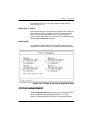
1200217L1 T3SU 300
1200217L2 T3SU 300 with Internal Modem
1200218L1 HSSI DTE Interface Card
1200219L1 V.35 DTE Interface Card

Trademark Information:
OpenView is a trademark of Hewlett-Packard Company.
Spectrum is a registered trademark of Cabletron.
Netview is a registered trademark of IBM.
901 Explorer Boulevard
P.O. Box 140000
Huntsville, AL 35814-4000
Phone: (256) 963-8000
© 1998 ADTRAN, Inc.
All rights reserved.
Printed in USA.

iii
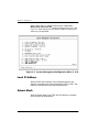
ABOUT THIS MANUAL
This manual is arranged so you can quickly and easily find the information
you need. The following is an overview of the contents of this manual:
• Chapter 1, Introduction, familiarizes you with T3 networks and T3SU 300
highlights and gives a brief explanation of options that may be purchased
for use with the T3SU 300.
• Chapter 2, Installation and Operation, describes the T3SU 300 connectors
(pin assignments are given in Appendix A), provides installation instruc-
tions, and explains how to operate your T3SU 300 using the terminal
interface.
• Chapter 3, Configuration, explains how to access the T3SU 300 Configu-
ration menu, describes selections made in the Configuration menus, and
provides a menu tree of all of the available Configuration options.
• Chapter 4, Status, describes each field of the Status menu.
• Chapter 5, Statistics, explains how to access statistical information for the
T3SU 300 and describes each field.
• Chapter 6, Diagnostics, explains how to diagnose problems using loop-
back and BERT tests.
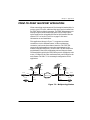
• Chapter 7, Applications, provides examples of some common T3SU 300
applications. This chapter includes network diagrams as well as configu-
ration tables for each example.
• Appendix A provides pinouts for the T3SU 300 connectors.
• Appendix B contains product specifications.
• Appendix C is a list of acronyms and abbreviations used in this docu-
ment.
• Appendix D is a glossary.

iv
IMPORTANT SAFETY INSTRUCTIONS
SAVE THESE INSTRUCTIONS
When using your telephone equipment, please follow these basic safety precautions
to reduce the risk of fire, electrical shock, or personal injury:
1. Do not use this product near water, such as near a bath tub, wash bowl, kitchen
sink, laundry tub, in a wet basement, or near a swimming pool.
2. Avoid using a telephone (other than a cordless-type) during an electrical storm.
There is a remote risk of shock from lightning.
3. Do not use the telephone to report a gas leak in the vicinity of the leak.
4. Use only the power cord, power supply, and/or batteries indicated in the manual.
Do not dispose of batteries in a fire. They may explode. Check with local codes
for special disposal instructions.
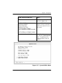
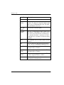
Notes provide additional useful information.
Cautions signify information that could prevent service interrup-
tion.
Warnings provide information that could prevent damage to the
equipment or endangerment to human life.

v
FCC regulations require that the following information be provided in this manual:
1. This equipment complies with Part 68 of FCC rules. On the bottom of the equip-
ment housing is a label showing the FCC registration number and ringer equiva-
lence number (REN) for this equipment. If requested, provide this information to
the telephone company.
2. If this equipment causes harm to the telephone network, the telephone company
may temporarily discontinue service. If possible, advance notification is given;
otherwise, notification is given as soon as possible. The telephone company will
advise the customer of the right to file a complaint with the FCC.
3. The telephone company may make changes in its facilities, equipment, opera-
tions, or procedures that could affect the proper operation of this equipment.
Advance notification and the opportunity to maintain uninterrupted service are
given.
4. If experiencing difficulty with this equipment, please contact ADTRAN for repair
and warranty information. The telephone company may require this equipment
to be disconnected from the network until the problem is corrected or it is certain
the equipment is not malfunctioning.
5. This unit contains no user-serviceable parts.
6. An FCC compliant telephone cord with a modular plug is provided with this
equipment. This equipment is designed to be connected to the telephone network
or premises wiring using an FCC compatible modular jack, which is Part 68 com-
pliant.
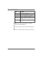
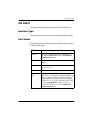
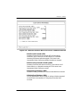
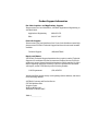
7. The following information may be required when applying to the local telephone
company for a dial-up line for the V.34 modem:
8. The REN is useful in determining the quantity of devices you may connect to
your telephone line and still have all of those devices ring when your number is
called. In most areas, the sum of the RENs of all devices should not exceed five.
To be certain of the number of devices you may connect to your line as deter-
mined by the REN, call your telephone company to determine the maximum REN
for your calling area.
9. This equipment may not be used on coin service provided by the telephone com-
pany. Connection to party lines is subject to state tariffs. Contact your state pub-
lic utility commission or corporation commission for information.
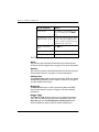
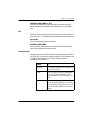
Service Type REN FIC USOC
Loop Start (V.34) 0.8B/0.4A 02LS2 RJ-11C

vi
YEAR 2000 COMPLIANCE
All ADTRAN transmission hardware and software products have been tested and
found to be fully compliant with the YEAR 2000 requirements. This is true for all
models and revisions regardless of the date of manufacture or delivery.
Users who wish to independently verify that specific products are in compliance may
contact ADTRAN Technical Support at 1-888-423-8726.

vii
FEDERAL COMMUNICATIONS COMMISSION
RADIO FREQUENCY INTERFERENCE STATEMENT
This equipment has been tested and found to comply with the limits for a Class A dig-
ital device, pursuant to Part 15 of the FCC Rules. These limits are designed to provide
reasonable protection against harmful interference when the equipment is operated in
a commercial environment. This equipment generates, uses, and can radiate radio fre-
quency energy and, if not installed and used in accordance with the instruction man-
ual, may cause harmful interference to radio frequencies. Operation of this equipment
in a residential area is likely to cause harmful interference in which case the user will
be required to correct the interference at his own expense.
Shielded cables must be used with this unit to ensure compliance with Class A FCC
limits.
CANADIAN EMISSIONS REQUIREMENTS
This digital apparatus does not exceed the Class A limits for radio noise emissions
from digital apparatus as set out in the interference-causing equipment standard enti-
tled “Digital Apparatus,” ICES-003 of the Department of Communications.
Cet appareil nuerique respecte les limites de bruits radioelectriques applicables aux
appareils numeriques de Class A prescrites dans la norme sur le materiel brouilleur:
“Appareils Numeriques,” NMB-003 edictee par le ministre des Communications.
Changes or modifications to this unit not expressly approved by the par-
ty responsible for compliance could void the user's authority to operate
the equipment.

viii
CANADIAN EQUIPMENT LIMITATIONS
Notice: The Canadian Industry and Science Canada label identifies certified equip-
ment. This certification means that the equipment meets certain telecommunications
network protective, operational, and safety requirements. The Department does not
guarantee the equipment will operate to the user’s satisfaction.
Before installing this equipment, users should ensure that it is permissible to be con-
nected to the facilities of the local telecommunications company. The equipment must
also be installed using an acceptable methods of connection. In some cases, the com-
pany’s inside wiring associated with a single line individual service may be extended
by means of a certified connector assembly (telephone extension cord). The customer
should be aware that compliance with the above limitations may not prevent degra-
dation of service in some situations.
Repairs to certified equipment should be made by an authorized Canadian mainte-
nance facility designated by the supplier. Any repairs or alterations made by the user
to this equipment, or equipment malfunctions, may give the telecommunications
company cause to request the user to disconnect the equipment.
Users should ensure for their own protection that the electrical ground connections of
the power utility, telephone lines and internal metallic water pipe system, if present,
are connected together. This precaution may be particularly important in rural areas.
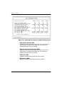
The Load Number (LN) assigned to each terminal device denotes the percentage of
the total load to be connected to a telephone loop which is used by the device, to pre-
vent overloading. The termination on a loop may consist of any combination of
devices subject only to the requirement that the total of the Load Numbers of all
devices does not exceed 100.
Users should not attempt to make such connections themselves, but should
contract the appropriate electric inspection authority, or an electrician, as
appropriate.

61200217L1-1 T3SU 300 User Manual ix
Table of Contents
Chapter 1. Introduction..................................................................................................... 1-1
Product Overview ...............................................................................................................1-1
T3 Overview ......................................................................................................................... 1-2
SNMP .................................................................................................................................... 1-2
TELNET ................................................................................................................................ 1-3
Interface Option Cards .......................................................................................................1-4
HSSI Card...................................................................................................................... 1-4
V.35 Card....................................................................................................................... 1-4
Warranty and Customer Service .......................................................................................1-5
Chapter 2. Installation and Operation ...........................................................................2-1
Unpack, Inspect, Power Up ...............................................................................................2-1
Receiving Inspection.................................................................................................... 2-1
Installing the Unit ................................................................................................................2-2
Rackmount Installation............................................................................................... 2-2
Desktop Installation..................................................................................................... 2-3
Rear Panel .............................................................................................................................2-3
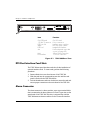
DTE Port Interface Card Slots.................................................................................... 2-4
Alarm Connector.......................................................................................................... 2-4
DTE Port 1 (HSSI Interface)........................................................................................ 2-5
Auxiliary Port............................................................................................................... 2-5
LAN Port....................................................................................................................... 2-6
DS3 Interface................................................................................................................. 2-6
Front Panel ........................................................................................................................... 2-6
Control Port .................................................................................................................. 2-6
LED Descriptions......................................................................................................... 2-9
Chapter 3. Configuration..................................................................................................3-1
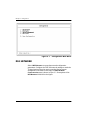
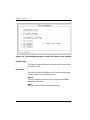
DS3 Network ........................................................................................................................3-2
DS3 Framing................................................................................................................. 3-3

Table of Contents
x T3SU 300 User Manual 61200217L1-1
Line Length ................................................................................................................... 3-3
DS3 Timing.................................................................................................................... 3-3
DS3 Scrambler............................................................................................................... 3-4
Data Link....................................................................................................................... 3-4
Remote Auto-Configuration....................................................................................... 3-4
DTE Ports ..............................................................................................................................3-4
Port Selections 1-4 ........................................................................................................ 3-5
Timed Profiles............................................................................................................. 3-10
System Management .........................................................................................................3-11
Local IP Address ........................................................................................................ 3-12
Subnet Mask................................................................................................................ 3-12
Gateway IP Address.................................................................................................. 3-13
Remote IP Address..................................................................................................... 3-13
IP Security ................................................................................................................... 3-13
IP Hosts........................................................................................................................ 3-13
Management Port....................................................................................................... 3-13
Auxiliary Port Mode.................................................................................................. 3-13
Modem Mode ............................................................................................................. 3-14
Auxiliary Port Baud Rate.......................................................................................... 3-14
Read Community Name ........................................................................................... 3-14
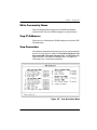
Write Community Name .......................................................................................... 3-15
Trap IP Addresses...................................................................................................... 3-15
Trap Generation ......................................................................................................... 3-15
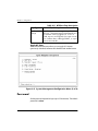
Password ..................................................................................................................... 3-18
Unit ID ......................................................................................................................... 3-19
Terminal Timeout....................................................................................................... 3-19
Date/Time................................................................................................................... 3-19
Alarm Relay ................................................................................................................ 3-19
Dialup Options........................................................................................................... 3-19
Utilities ................................................................................................................................3-22
Save Configuration ............................................................................................................3-24
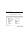
Chapter 4. Status.................................................................................................................4-1
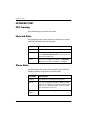
Network Port ........................................................................................................................4-2
DS3 Framing ................................................................................................................. 4-2
Network State............................................................................................................... 4-2
Alarm State.................................................................................................................... 4-2
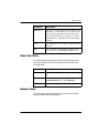
Data Link State.............................................................................................................. 4-3
Remote State.................................................................................................................. 4-3
DTE Ports ..............................................................................................................................4-5
Interface Type............................................................................................................... 4-5

Table of Contents
61200217L1-1 T3SU 300 User Manual xi
Port Status..................................................................................................................... 4-5
Bandwidth..................................................................................................................... 4-6
DTE Leads..................................................................................................................... 4-6
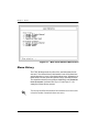
Chapter 5. Statistics............................................................................................................5-1
Viewing Statistical information ......................................................................................... 5-1
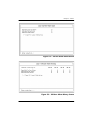
Alarm History............................................................................................................... 5-2
Performance Parameters............................................................................................. 5-4
Chapter 6. Diagnostics ......................................................................................................6-1
DS3 ................................................................................................................................. 6-2
DTE Ports 1-4................................................................................................................ 6-5
BERT Configuration .................................................................................................... 6-9
Chapter 7. Applications ....................................................................................................7-1
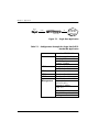
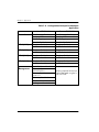
Single Port Full T3 Bandwidth ..........................................................................................7-1
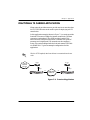
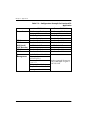
Point-to-Point Multiport Application ..............................................................................7-3
Fractional T3 Carrier Application ..................................................................................... 7-5
Remote SNMP Management Application .......................................................................7-7
Appendix A. Pinouts ........................................................................................................A-1
Appendix B. Specifications Summary...........................................................................B-1
Appendix C. Acronyms/Abbreviations......................................................................... C-1
Appendix D. Glossary......................................................................................................D-1

Table of Contents
xii T3SU 300 User Manual 61200217L1-1

61200217L1-1 T3SU 300 User Manual xiii
List of Figures
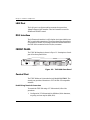
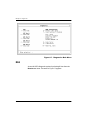
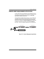
Figure 2-1. T3SU 300 Rear View.......................................................................................2-4
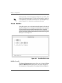
Figure 2-2. T3SU 300 Front Panel......................................................................................2-6
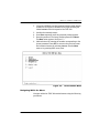
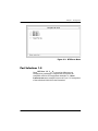
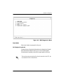
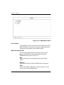
Figure 2-3. Terminal Main Menu......................................................................................2-7
Figure 3-1. Configuration Main Menu............................................................................3-2
Figure 3-2. DS3 Network Configuration Menu .............................................................. 3-3
Figure 3-3. DTE Ports Menu ..............................................................................................3-5
Figure 3-4. Port Configuration Menu (with V.35 interface card installed).................. 3-6
Figure 3-5. Timed Profiles Screen....................................................................................3-10
Figure 3-6. Example of a Profile Configuration Menu..................................................3-11
Figure 3-7. System Management Configuration Menu (1 of 2)..................................3-12
Figure 3-8. Trap Generation Menu..................................................................................3-15
Figure 3-9. System Management Configuration Menu (2 of 2)..................................3-18
Figure 3-10. Dialup Options Menu................................................................................. 3-20
Figure 3-11. System Utilities Menu.................................................................................3-23
Figure 3-12. T3SU 300 Configuration Menu Tree .........................................................3-25
Figure 4-1. Status Menu...................................................................................................... 4-1
Figure 5-1. Main Local Statistics Menu Screen................................................................ 5-2
Figure 5-2. Current Alarm Count Screen......................................................................... 5-3
Figure 5-3. 24-Hour Alarm History Screen......................................................................5-3
Figure 5-4. Network Statistics Menu for Current 15-Minute Interval......................... 5-5
Figure 5-5. Network Port Statistics 24-Hour History Screen........................................ 5-6
Figure 5-6. Network Port Statistics Menu (24-Hour Totals)..........................................5-7
Figure 6-1. Diagnostics Main Menu..................................................................................6-2
Figure 6-2. DS3 Diagnostics Menu.................................................................................... 6-3
Figure 6-3. DS3 Payload Loopback Test...........................................................................6-4

List of Figures
xiv T3SU 300 User Manual 61200217L1-1
Figure 6-4. Line Loopback Test..........................................................................................6-4
Figure 6-5. DTE Port Diagnostics Menu...........................................................................6-5
Figure 6-6. Payload Loopback Test ...................................................................................6-6
Figure 6-7. Payload BERT Test...........................................................................................6-7
Figure 6-8. DTE Loopback Test..........................................................................................6-7
Figure 6-9. Payload and DTE Loopback Test...................................................................6-8
Figure 6-10. BERT Pattern Menu.....................................................................................6-10
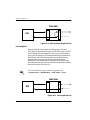
Figure 7-1. Single Port Application...................................................................................7-2
Figure 7-2. Multiport Application.....................................................................................7-3
Figure 7-3. Fractional Application ....................................................................................7-5
Figure 7-4. Remote Management Application ................................................................7-7

61200217L1-1 T3SU 300 User Manual xv
List of Tables
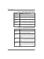
Table 3-1. Near End Alarm Trap Descriptions ............................................................. 3-16
Table 3-2. Far End Alarm Trap Descriptions ..............................................................3-16
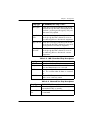
Table 3-3. MIB II Standard Trap Descriptions .............................................................. 3-17
Table 3-4. Network Test Trap Descriptions...................................................................3-17
Table 3-5. DTE Port Trap Description............................................................................3-18
Table 4-1. LA and LB Leads............................................................................................... 4-7
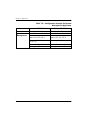
Table 7-1. Configuration Example for Single Port Full T3 Bandwidth Application . 7-2
Table 7-2. Configuration Example for Multiport Application...................................... 7-4
Table 7-3. Configuration Example for Fractional T3 Application................................ 7-6
Table 7-4. Configuration Example for Remote Management Application................. 7-8
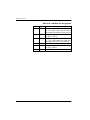
Table A-1. Control and Auxiliary Port Pin Assignments.............................................A-1
Table A-2. HSSI Interface Pin Assignments...................................................................A-2
Table A-3. V.35 Interface Card Pin Assignments ..........................................................A-3
Table A-4. LAN Port Pin Assignments...........................................................................A-4

List of Tables
xvi T3SU 300 User Manual 61200217L1-1

61200217L1-1 T3SU 300 User Manual 1-1
Chapter 1 Introduction
PRODUCT OVERVIEW
The T3SU 300 is a multiport DSU/CSU (data service unit/channel
service unit) that provides access to T3 services. The unit provides a
cost-effective, versatile approach for migrating T1 services to T3.
The TDM (time division multiplexer) multiport design allows you
to share the cost of a T3 line between multiple applications. This
unit maximizes the use of T3 services, providing up to four data
ports capable of transmitting and receiving high-capacity, real time
data.
A HSSI (high speed serial interface) port is built in along with three
slots which accept additional HSSI or V.35 interface cards. The HSSI
interfaces support rates between 75 kbps and 44.2 Mbps in 75 kbps
increments. The high speed V.35 interface option supports rates up
to 10 Mbps in increments of 75 kbps.
Embedded SNMP (simple network management protocol) and
TELNET are available through either a SLIP/PPP or a 10baseT
ethernet port. Through the Management Information Base II(MIB
II), RFC 1407 standards, and an ADTRAN enterprise MIB, the
T3SU 300 can be configured, monitored, and diagnosed using
standard SNMP network management programs such as Hewlett
Packard’s HP OpenView™, IBM’s Netview™, and Cabletron’s
Spectrum™.
Complete configuration, diagnostics, and performance monitoring
are available through SNMP, TELNET, or a VT 100 terminal
interface. This connection can be made via ethernet, a local EIA-232

Chapter 1. Introduction
1-2 T3SU 300 User Manual 61200217L1-1
link, or through the built-in V.34 modem (1200217L2 only).
Advanced dial-out on trap capabilities through the built-in modem
allow the T3SU 300 to contact remote hosts and alert them to DSX-3
network conditions (without dedicated management connections).
The T3SU 300 is designed for either desktop use or installation in a
19-inch rack.
The major features or the T3SU 300 are as follows:
• Full feature multiport T3 DSU/CSU
• Maximum of four user data ports (HSSI or high speed V.35)
available
• Automatic or manual remote configuration
• Embedded SNMP and TELNET management through 10baseT
ethernet or SLIP/PPP
• Detailed performance monitoring for local and remote units
• Simplified configuration through detailed VT 100 terminal
menu structure
• Optional integrated V.34 modem for dial-up and dial-out
access (product version 1200212L2 only)
• Standard 5-year warranty
T3 OVERVIEW
T3 provides the same bandwidth as 28 T1s and is used to
interconnect high-speed bridges, routers, front-end processors, and
data terminal equipment (DTE). T3 service plays a major role in
Internet backbones and public organizations needing broad
bandwidth for WAN (wide area network) connectivity.
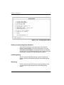
SNMP
The T3SU 300's embedded SNMP feature allows the unit to be
accessed and controlled by a network manager through either the
auxiliary (AUX) control port or the 10baseT local area network

Chapter 1. Introduction
61200217L1-1 T3SU 300 User Manual 1-3
(LAN) port. The T3SU 300 supports the MIB-II standard, RFC 1213,
and the ADTRAN Enterprise Specific MIB.
The term SNMP broadly refers to the message protocols used to
exchange information between the network management system
(NMS) and the managed devices, as well as to the structure of
device management databases. SNMP has three basic components:
Network Manager
Control programs that collect, control, and present data pertinent to
the operation of the network devices. These programs reside on a
network management station.
Agent
Control program that resides in every network device. This
program responds to queries and commands from the network
manager, returns requested information or invokes configuration
changes initiated by the manager, and sends unsolicited traps to the
manager.
MIB
Industry standard presentation of all status and configuration
parameters supported by a network device.
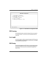
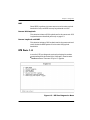
TELNET
TELNET provides a password-protected, remote login facility to
the T3SU 300 that allows a remote user to control the T3SU 300
through the terminal menus. Only one TELNET session may be
active at a time.
MIB files are available from ADTRAN in the support section of the
ADTRAN Web page at www.adtran.com.

Chapter 1. Introduction
1-4 T3SU 300 User Manual 61200217L1-1
INTERFACE OPTION CARDS
Optional interface cards may be purchased to equip the T3SU 300
with up to three additional ports. Both HSSI and V.35 interface
cards are available.
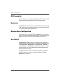
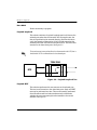
HSSI Card
The optional HSSI card plugs into one of the three card slots on the
rear of the T3SU 300. With optional HSSI cards installed, the total
44.2 Mbps bandwidth of the T3 can be divided among the total
number of ports to provide multiple data channels over the T3. The
total bandwidth of the T3 can be divided among the available ports
in any fashion, as long as the divisions are on 75 kbps boundaries.
The HSSI card can be hot inserted or swapped. When it is inserted
in a slot on the rear panel and its faceplate is secured to the rear
panel of the T3SU 300 with the integral thumb screws, a PCMCIA
type connector on the card mates with a compatible connector on
the main board of the T3SU 300. A standard 50-pin HSSI connector
is then available for DTE connections. See the section DTE Port
Interface Card Slots on page 2-4 for more information on installing
option cards.
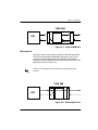
V.35 Card
The optional V.35 card plugs into the card slots on the rear of the
T3SU 300 to provide a V.35-type DTE interface. Operation of the
V.35 card is similar to that of the HSSI card except that the
maximum bandwidth of the V.35 card is limited to 10 Mbps.
Like the HSSI card, the V.35 card can be hot inserted or swapped,
and it installs just as the HSSI card does. Instead of the standard
HSSI connector, this card contains a standard 34-pin V.35 connector
for DTE connections. See the section DTE Port Interface Card Slots on
page 2-4 for more information on installing option cards.
Page is loading ...
Page is loading ...
Page is loading ...
Page is loading ...
Page is loading ...
Page is loading ...
Page is loading ...
Page is loading ...
Page is loading ...
Page is loading ...
Page is loading ...
Page is loading ...
Page is loading ...
Page is loading ...
Page is loading ...
Page is loading ...
Page is loading ...
Page is loading ...
Page is loading ...
Page is loading ...
Page is loading ...
Page is loading ...
Page is loading ...
Page is loading ...
Page is loading ...
Page is loading ...
Page is loading ...
Page is loading ...
Page is loading ...
Page is loading ...
Page is loading ...
Page is loading ...
Page is loading ...
Page is loading ...
Page is loading ...
Page is loading ...
Page is loading ...
Page is loading ...
Page is loading ...
Page is loading ...
Page is loading ...
Page is loading ...
Page is loading ...
Page is loading ...
Page is loading ...
Page is loading ...
Page is loading ...
Page is loading ...
Page is loading ...
Page is loading ...
Page is loading ...
Page is loading ...
Page is loading ...
Page is loading ...
Page is loading ...
Page is loading ...
Page is loading ...
Page is loading ...
Page is loading ...
Page is loading ...
Page is loading ...
Page is loading ...
Page is loading ...
Page is loading ...
Page is loading ...
Page is loading ...
Page is loading ...
Page is loading ...
Page is loading ...
Page is loading ...
Page is loading ...
Page is loading ...
Page is loading ...
Page is loading ...
Page is loading ...
Page is loading ...
Page is loading ...
Page is loading ...
Page is loading ...
Page is loading ...
Page is loading ...
Page is loading ...
Page is loading ...
Page is loading ...
Page is loading ...
Page is loading ...
Page is loading ...
Page is loading ...
Page is loading ...
Page is loading ...
Page is loading ...
Page is loading ...
Page is loading ...
Page is loading ...
Page is loading ...
Page is loading ...
Page is loading ...
Page is loading ...
Page is loading ...
Page is loading ...
Page is loading ...
Page is loading ...
-
 1
1
-
 2
2
-
 3
3
-
 4
4
-
 5
5
-
 6
6
-
 7
7
-
 8
8
-
 9
9
-
 10
10
-
 11
11
-
 12
12
-
 13
13
-
 14
14
-
 15
15
-
 16
16
-
 17
17
-
 18
18
-
 19
19
-
 20
20
-
 21
21
-
 22
22
-
 23
23
-
 24
24
-
 25
25
-
 26
26
-
 27
27
-
 28
28
-
 29
29
-
 30
30
-
 31
31
-
 32
32
-
 33
33
-
 34
34
-
 35
35
-
 36
36
-
 37
37
-
 38
38
-
 39
39
-
 40
40
-
 41
41
-
 42
42
-
 43
43
-
 44
44
-
 45
45
-
 46
46
-
 47
47
-
 48
48
-
 49
49
-
 50
50
-
 51
51
-
 52
52
-
 53
53
-
 54
54
-
 55
55
-
 56
56
-
 57
57
-
 58
58
-
 59
59
-
 60
60
-
 61
61
-
 62
62
-
 63
63
-
 64
64
-
 65
65
-
 66
66
-
 67
67
-
 68
68
-
 69
69
-
 70
70
-
 71
71
-
 72
72
-
 73
73
-
 74
74
-
 75
75
-
 76
76
-
 77
77
-
 78
78
-
 79
79
-
 80
80
-
 81
81
-
 82
82
-
 83
83
-
 84
84
-
 85
85
-
 86
86
-
 87
87
-
 88
88
-
 89
89
-
 90
90
-
 91
91
-
 92
92
-
 93
93
-
 94
94
-
 95
95
-
 96
96
-
 97
97
-
 98
98
-
 99
99
-
 100
100
-
 101
101
-
 102
102
-
 103
103
-
 104
104
-
 105
105
-
 106
106
-
 107
107
-
 108
108
-
 109
109
-
 110
110
-
 111
111
-
 112
112
-
 113
113
-
 114
114
-
 115
115
-
 116
116
-
 117
117
-
 118
118
-
 119
119
-
 120
120
-
 121
121
-
 122
122


Ask a question and I''ll find the answer in the document
Finding information in a document is now easier with AI
Related papers
-
ADTRAN T3SU 300 User manual
-
-
-
-
-
-
ADTRAN T3SU 300 Quick start guide
-
-
-
Other documents
-
 Shenzhen Eview Gps Technology DS3 User guide
-
 Metrodata DC3445 User manual
-
Black Box CSU/DSU User manual
-
CTC Union I-DSL128 User manual
-
Verilux 41TDM User manual
-
Digi 90031300 User manual
-
 Paradyne ACCULINK 3164 Supplementary Manual
-
 Quick Eagle Networks DL3150 User manual
-
 Quick Eagle Networks DL3800E User manual
-
Cisco CAB-T3E3-PL-AD= Datasheet


