Page is loading ...

System 5
crcr
crcr
cr
System Switcher
68-388-01
Printed in the USA

This symbol is intended to alert the user of important operating and maintenance
(servicing) instructions in the literature provided with the equipment.
This symbol is intended to alert the user of the presence of uninsulated dangerous
voltage within the product's enclosure that may present a risk of electric shock.
Caution
Read Instructions • Read and understand all safety and operating instructions before using the
equipment.
Retain Instructions • The safety instructions should be kept for future reference.
Follow Warnings • Follow all warnings and instructions marked on the equipment or in the user
information.
Avoid Attachments • Do not use tools or attachments that are not recommended by the equipment
manufacturer because they may be hazardous.
Warning
Power sources • This equipment should be operated only from the power source indicated on the
product. This equipment is intended to be used with a main power system with a grounded
(neutral) conductor. The third (grounding) pin is a safety feature, do not attempt to bypass or
disable it.
Power disconnection • To remove power from the equipment safely, remove all power cords from
the rear of the equipment, or the desktop power module (if detachable), or from the power
source receptacle (wall plug).
Power cord protection • Power cords should be routed so that they are not likely to be stepped on or
pinched by items placed upon or against them.
Servicing • Refer all servicing to qualified service personnel. There are no user-serviceable parts
inside. To prevent the risk of shock, do not attempt to service this equipment yourself because
opening or removing covers may expose you to dangerous voltage or other hazards.
Slots and openings • If the equipment has slots or holes in the enclosure, these are provided to
prevent overheating of sensitive components inside. These openings must never be blocked by
other objects.
Lithium battery • There is a danger of explosion if battery is incorrectly replaced. Replace it only
with the same or equivalent type recommended by the manufacturer. Dispose of used batteries
according to the manufacturer's instructions.
Ce symbole sert à avertir l’utilisateur que la documentation fournie avec le matériel
contient des instructions importantes concernant l’exploitation et la maintenance
(réparation).
Ce symbole sert à avertir l’utilisateur de la présence dans le boîtier de l’appareil de
tensions dangereuses non isolées posant des risques d’électrocution.
Attention
Lire les instructions• Prendre connaissance de toutes les consignes de sécurité et d’exploitation avant
d’utiliser le matériel.
Conserver les instructions• Ranger les consignes de sécurité afin de pouvoir les consulter à l’avenir.
Respecter les avertissements • Observer tous les avertissements et consignes marqués sur le matériel ou
présentés dans la documentation utilisateur.
Eviter les pièces de fixation • Ne pas utiliser de pièces de fixation ni d’outils non recommandés par le
fabricant du matériel car cela risquerait de poser certains dangers.
Avertissement
Alimentations• Ne faire fonctionner ce matériel qu’avec la source d’alimentation indiquée sur
l’appareil. Ce matériel doit être utilisé avec une alimentation principale comportant un fil de
terre (neutre). Le troisième contact (de mise à la terre) constitue un dispositif de sécurité :
n’essayez pas de la contourner ni de la désactiver.
Déconnexion de l’alimentation• Pour mettre le matériel hors tension sans danger, déconnectez tous
les cordons d’alimentation de l’arrière de l’appareil ou du module d’alimentation de bureau (s’il
est amovible) ou encore de la prise secteur.
Protection du cordon d’alimentation • Acheminer les cordons d’alimentation de manière à ce que
personne ne risque de marcher dessus et à ce qu’ils ne soient pas écrasés ou pincés par des
objets.
Réparation-maintenance • Faire exécuter toutes les interventions de réparation-maintenance par un
technicien qualifié. Aucun des éléments internes ne peut être réparé par l’utilisateur. Afin
d’éviter tout danger d’électrocution, l’utilisateur ne doit pas essayer de procéder lui-même à ces
opérations car l’ouverture ou le retrait des couvercles risquent de l’exposer à de hautes tensions
et autres dangers.
Fentes et orifices • Si le boîtier de l’appareil comporte des fentes ou des orifices, ceux-ci servent à
empêcher les composants internes sensibles de surchauffer. Ces ouvertures ne doivent jamais
être bloquées par des objets.
Lithium Batterie • Il a danger d'explosion s'll y a remplacment incorrect de la batterie. Remplacer
uniquement avec une batterie du meme type ou d'un ype equivalent recommande par le
constructeur. Mettre au reut les batteries usagees conformement aux instructions du fabricant.
Safety Instructions • English
Consignes de Sécurité • Français
Sicherheitsanleitungen • Deutsch
Dieses Symbol soll den Benutzer auf wichtige Anleitungen zur Bedienung und
Wartung (Instandhaltung) in der Dokumentation hinweisen, die im Lieferumfang
dieses Gerätes enthalten ist.
Dieses Symbol soll den Benutzer darauf aufmerksam machen, daß im Inneren des
Gehäuses dieses Produktes gefährliche Spannungen, die nicht isoliert sind und
die einen elektrischen Schock verursachen können, herrschen.
Achtung
Lesen der Anleitungen • Bevor Sie das Gerät zum ersten Mal verwenden, sollten Sie alle Sicherheits-und
Bedienungsanleitungen genau durchlesen und verstehen.
Aufbewahren der Anleitungen • Die Sicherheitsanleitungen sollten aufbewahrt werden, damit Sie
später darauf zurückgreifen können.
Befolgen der Warnhinweise • Befolgen Sie alle Warnhinweise und Anleitungen auf dem Gerät oder in
der Benutzerdokumentation.
Keine Zusatzgeräte • Verwenden Sie keine Werkzeuge oder Zusatzgeräte, die nicht ausdrücklich vom
Hersteller empfohlen wurden, da diese eine Gefahrenquelle darstellen können.
Vorsicht
Stromquellen • Dieses Gerät sollte nur über die auf dem Produkt angegebene Stromquelle betrieben
werden. Dieses Gerät wurde für eine Verwendung mit einer Hauptstromleitung mit einem
geerdeten (neutralen) Leiter konzipiert. Der dritte Stift oder Kontakt ist für einen Erdschluß, und
stellt eine Sicherheitsfunktion dar und sollte nicht umgangen oder außer Betrieb gesetzt werden.
Stromunterbrechung • Um das Gerät auf sichere Weise vom Netz zu trennen, sollten Sie alle
Netzkabel aus der Rückseite des Gerätes oder aus dem Desktop-Strommodul (falls dies möglich
ist) oder aus der Wandsteckdose ziehen.
Schutz des Netzkabels • Netzkabel sollten stets so verlegt werden, daß sie nicht im Weg liegen und
niemand darauf treten kann oder Objekte darauf- oder unmittelbar dagegengestellt werden
können.
Wartung • Alle Wartungsmaßnahmen sollten nur von qualifiziertem Servicepersonal durchgeführt
werden. Im Inneren des Gerätes sind keine Teile enthalten, die vom Benutzer gewartet werden können.
Zur Vermeidung eines elektrischen Schocks versuchen Sie in keinem Fall, dieses Gerät selbst zu
warten, da beim Öffnen oder Entfernen der Abdeckungen die Gefahr eines elektrischen Schlags
oder andere Gefahren bestehen.
Schlitze und Öffnungen • Wenn das Gerät Schlitze oder Löcher im Gehäuse aufweist, dienen diese
zur Vermeidung einer Überhitzung der empfindlichen Teile im Inneren. Diese Öffnungen dürfen
niemals von anderen Objekten blockiert werden.
Litium-Batterie • Explosionsgefahr, falls die Batterie nicht richtig ersetzt wird. Ersetzen Sie nur
durch die gleiche oder einen vergleichbaren Batterietyp, der auch vom Hersteller empfohlen
wird. Entsorgung der verbrauchten Batterien bitte gemäß den Herstelleranweisungen.
Este símbolo se utiliza para advertir al usuario sobre instrucciones importantes de
operación y mantenimiento (o cambio de partes) que se desean destacar en el
contenido de la documentación suministrada con los equipos.
Este símbolo se utiliza para advertir al usuario sobre la presencia de elementos con
voltaje peligroso sin protección aislante, que puedan encontrarse dentro de la caja
o alojamiento del producto, y que puedan representar riesgo de electrocución.
Precaucion
Leer las instrucciones • Leer y analizar todas las instrucciones de operación y seguridad, antes de usar
el equipo.
Conservar las instrucciones • Conservar las instrucciones de seguridad para futura consulta.
Obedecer las advertencias • Todas las advertencias e instrucciones marcadas en el equipo o en la
documentación del usuario, deben ser obedecidas.
Evitar el uso de accesorios • No usar herramientas o accesorios que no sean especificamente
recomendados por el fabricante, ya que podrian implicar riesgos.
Advertencia
Alimentación eléctrica • Este equipo debe conectarse únicamente a la fuente/tipo de alimentación
eléctrica indicada en el mismo. La alimentación eléctrica de este equipo debe provenir de un
sistema de distribución general con conductor neutro a tierra. La tercera pata (puesta a tierra) es
una medida de seguridad, no puentearia ni eliminaria.
Desconexión de alimentación eléctrica • Para desconectar con seguridad la acometida de
alimentación eléctrica al equipo, desenchufar todos los cables de alimentación en el panel trasero
del equipo, o desenchufar el módulo de alimentación (si fuera independiente), o desenchufar el
cable del receptáculo de la pared.
Protección del cables de alimentación • Los cables de alimentación eléctrica se deben instalar en
lugares donde no sean pisados ni apretados por objetos que se puedan apoyar sobre ellos.
Reparaciones/mantenimiento • Solicitar siempre los servicios técnicos de personal calificado. En el
interior no hay partes a las que el usuario deba acceder. Para evitar riesgo de electrocución, no
intentar personalmente la reparación/mantenimiento de este equipo, ya que al abrir o extraer las
tapas puede quedar expuesto a voltajes peligrosos u otros riesgos.
Ranuras y aberturas • Si el equipo posee ranuras o orificios en su caja/alojamiento, es para evitar el
sobrecalientamiento de componentes internos sensibles. Estas aberturas nunca se deben obstruir
con otros objetos.
Batería de litio • Existe riesgo de explosión si esta batería se coloca en la posición incorrecta. Cambiar
esta batería únicamente con el mismo tipo (o su equivalente) recomendado por el fabricante.
Desachar las baterías usadas siguiendo las instrucciones del fabricante.
Instrucciones de seguridad • Español
Precautions

Setup Mode procedures
Connections
QUICK START FOR SYSTEM 5
crcr
crcr
cr
SWITCHER
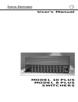
Enter Setup Mode, and then continue to procedure a, b, or c.
Use Setup Mode for each of the following procedures. To enter Setup Mode, press and hold all 3 Display buttons
(Power/Mute/Mode) on the front panel for 2 seconds. The Config LED lights. Continue to Clear, or to procedure a, b or
c. Once in Setup Mode (Config LED still On), you may move from one
procedure to another without returning to Normal operation. To Exit Setup
Mode, hold the same 3 Display buttons for 2 sec., or wait for 20 second
time-out (3 LEDs blink during the last 5 seconds).
To Clear existing configuration(s) (to factory default)
From Setup Mode, double-click the Room button. The Room LED blinks for
8 seconds. During that time, do one of the following:
Clear One – press the desired button to clear only its IR configuration.
Clear ALL (IR & other settings) – press all 3 Display buttons 2 seconds.
To Exit Clear, press the Room button.
a - Preset Attenuation for Audio Inputs – Audio must be present on each input, playing a loud
passage from each source, then use the following procedure to set each input.
1a. Double-click (press twice) the button for the Input to be adjusted. Its LED will blink continuously.
2a. Adjust Volume knob up (cw) until Clip LED is On or blinking frequently with sound level.
3a. Adjust Volume knob down (ccw) just until Clip LED is Off or blinks occasionally as the level peaks.
4a. Press the Input button again to save the setting.
5a. Repeat steps 1a through 4a for each audio input.
6a. While still in Setup mode, you may move directly to another procedure, or exit to normal mode.
b - Select input format for VID1 & VID2 (default = comp. video) In Setup Mode, do the following:
1b. Press & hold the Room button until finished with this operation. After 2 seconds, one of the VID1
LEDs lights. (During this operation, the appropriate LED lights to indicate the selected format.)
2b. Press VID1 input button to toggle between VID (Comp. Video) and Y/C (S-video) formats.
3b. Repeat step 2b to select the format for VID2 input.
4b. Release the Room button to return to Setup mode.
5b. While still in Setup mode, you may move directly to another procedure, or exit to normal mode.
c - Learn Infrared Signals from other devices’ remotes. In Setup Mode, do the following:
1c. Press the System 5 button to be programmed for 2 seconds. Config LED blinks to indicate “ready”.
2c. Point the IR source remote control directly at the System 5 IR Remote window and press the
button for the signal to be “learned”. Config remains On while TX & Retry LEDs blink to indicate
that the operation is complete. (If Retry = On and TX - Off, repeat this step).
Note: The Display Power button can learn 2 functions. See LED codes below for other responses.
3c. Repeat steps 1c and 2c to program the next button.
4c. While still in Setup
mode, you may move
directly to another
procedure, or exit.
1. Rear Panel Inputs
PC2 and PC3 –
Connect RGBS/
RGBHV sources,
such as from
Computer-Video
Interfaces. Connect
Audio if available.
2. Rear Panel Inputs
VID1 & VID2 – Connect
Composite Video or S-video sources and Audio, if
available. (Use Setup and then procedure “b” below to select Composite or S-video.)
3. Outputs – Connect RGBS/RGBHV, S-video and Composite Video to the Display Device (Projector), as required.
Connect Audio Preamp output to the input of a sound system or Amplified Out directly to Speakers.
4. Other – Connect RS-232 Host, SCP 100(s), Power Sensor, Room/Relay control and IR Emitter or Broadcaster.
5. Front Panel Input PC1 – Connect a VGA and Audio source (Laptop) to this input at any time.
6. Power – Apply power to the System 5cr and other devices.
7. Setup – Follow the
procedures below
to clear or set up
Audio levels, VID1
& VID2 input
formats and IR
learning (Projector
control, etc.)
Composite or S-video
S-video
S-video
S-video

Contents
Extron • System 5
cr
Switcher • User’s Manual
Chapter One • Introduction to System 5
crcr
crcr
cr
What is a System 5cr Switcher? ................................................................................................. 1-1
Controlling the System ................................................................................................... 1-1
Infrared learning for System Control .............................................................................. 1-2
Standard Features ......................................................................................................... 1-2
Inputs ............................................................................................................................. 1-2
Outputs .......................................................................................................................... 1-2
Options and Accessories ............................................................................................................ 1-3
Specifications ............................................................................................................................. 1-4
Chapter Two • Rear Panel Connections
Installation in Rack, on a Wall or Under a Table .......................................................................... 2-1
Panel Connections ..................................................................................................................... 2-1
Video Input Connections ................................................................................................ 2-1
Audio Input Connections ................................................................................................ 2-2
Video Output Connections ............................................................................................. 2-2
Audio Preamp Out Connection ...................................................................................... 2-4
Connecting Accessories ............................................................................................................. 2-4
Comm connector and Infrared Emitter ........................................................................... 2-5
Room/Relay connector .................................................................................................. 2-5
Chapter Three • Using the System 5
crcr
crcr
cr
Using the System 5cr.................................................................................................................. 3-1
Front Panel Controls and Indicators............................................................................... 3-1
Configuration Setup from the Front Panel................................................................................... 3-3
Infrared Programs and Libraries .................................................................................... 3-3
Enter Setup (Config) Mode ......................................................................................................... 3-3
Clear Configuration(s) .................................................................................................... 3-3
Preset Audio Input Attenuation Levels ........................................................................... 3-3
Select format for VID1 and/or VID2................................................................................ 3-4
Learn Infrared Signals from other devices’ remote controls. .......................................... 3-4
Remote Operation ...................................................................................................................... 3-5
Chapter Four • Windows® Control Software
Installing Windows® Control Software ........................................................................................ 4-1
Program Help ............................................................................................................................. 4-2
Program Operation ..................................................................................................................... 4-2
Power Up/Down Delay times ......................................................................................... 4-3
Auto Set Attenuators (set all audio input to the same level). .......................................... 4-3
Room Relay Mode (Latched/Momentary) ...................................................................... 4-3
RGB Delay Times .......................................................................................................... 4-4
Miscellaneous Options ................................................................................................... 4-4
Downloading from Extron’s IR Projector Library ......................................................................... 4-5
Saving a Configuration to a File ..................................................................................... 4-5
Loading Projector Drivers .............................................................................................. 4-6
Appendix A • Programming the System 5
crcr
crcr
cr
Remote Control Port (RS-232) ................................................................................................... A-1
Host-to-System 5 Instructions .....................................................................................................A-1
Simple Instruction Set – Command codes .....................................................................A-2
Definitions and Abbreviations: ........................................................................................A-2
Advanced Instructions – Reserved for Windows program ..........................................................A-3
Appendix B • Reference
System 5 Options ....................................................................................................................... B-1
Glossary of terms........................................................................................................................ B-3
Index ........................................................................................................................................... B-7
System 5
cr
Switcher User’s Manual
68-388-01, Rev. A, 09-99
i

1
Chapter One
Introduction to System 5
crcr
crcr
cr
What is the System 5
cr
?
Control of the Entire A/V System
Infrared Learning
Features & Options
Specifications
System 5
cr
Switcher
User’s Manual

Introduction and Features • Chapter 1
Extron • System 5
cr
Switcher • User’s Manual
What is a System 5
crcr
crcr
cr Switcher?
Throughout this manual, the terms System 5 and System 5cr are both
used to refer to the same product.
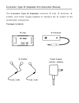
The System 5 provides central control for small audio/video installations.
The five inputs accept video formats from composite, S-video and
computer-video sources, together with line-level audio. In addition to
being a video/audio switcher, the System 5 combines the functions of
several devices, including projector control for LCD, DLP and Plasma
Displays. A “room” function allows control of such things as lighting or a
display screen and infrared “learning” adds control for one of many
different projectors.
Figure 1-1. Example of a System 5 as part of a video/audio system.
Controlling the System
The System 5 functions as a switcher as it comes out of the box.
However, to have projector control, it must be programmed. This can be
done by learning projector IR commands or by loading a set of commands
from Extron’s IR library into its memory. The IR library, as well as the
latest control software is available at www.extron.com. Control of the
System 5 and other devices can be done in several ways:
• The front panel
• Windows® control software from a PC
• Through RS-232 port by a PC, a touch screen panel, or any other device
capable of sending and receiving the serial port protocol.
• Optional control pads (SCP 100) can be mounted in a wall, or podium,
and hard-wired to the System 5. Each SCP 100 replicates the front panel
functions and can receive IR signals, and pass them to the System 5.
• The IR 40 remote control has each of the System 5 front panel functions.
POWER MUTE
DISPLAY
SCP 100
MODE
VOLU ME
AUDIO
ROOM
MAX.
CLIP
MIN.
PC1 PC2 PC3 VID1 VID2
IR REMOTE
VID
MAX.
CLIP
MIN.
TX
CONFIG
RETRY
Y/C
VID
Y/C
ROOM
DISPLAY
POWER MUTE MODE PC1 PC2 PC3
VOLUME
AUDIO
COMPUTERAUDIO
PC1 INPUT
IR REMOTE
VID1 VID2
50/60 Hz
100-240V 1.3A
RS-232
RGB
PC 2
PC 3
VID 1
VID 2
H/HV
V RG B
H/HV
VLR
RGB
H/HV
V
V/Y
V/Y
C
C
Y
CVID
PREAMP OUT
LR
LR
LR L
L
R
R
L
R
AUX 1 AUX 2
AMPLIFIED OUT
DISPLAY PWR
SENSOR
RELAY COMM.
RGB 406 Interface
Front
Rear
Control Pad
To Second Control Pad
INPUT
Video Cassette
Player
SVGA Compatible
Computer w/ Audio
SVGA Compatible Computer
Speakers
Powered Speakers
Document Camera
LCD Projector
Composite
S-video
IR 40
Remote
Computer
Interface
HIGH Z
75 Ohm
Laptop Computer
1-1

Chapter 1 • Introduction and Features
Extron • System 5
cr
Switcher • User’s Manual
Infrared Learning for System Control
The IR receiver window on the front panel also serves as a learning port
to add IR signals from other sources to the System 5 panel functions.
Then, when a panel function is selected, the learned IR signal is
transmitted into the room through the hard-wired IR emitter, or the
optional IR Broadcaster, to be received by the projector. IR commands for
the projector can be associated with each of the Display buttons (Power,
Mute and Mode) on the front panel as well as with each of the five input
buttons. Thus the System 5 switcher can control the projector. Stored
commands (learned or uploaded) in the System 5 memory are also
effective when using the IR 40, SCP 100 or RS-232 controls.
As an example, IR commands for the projector shown in Figure 1-1 can
be stored in the System 5 memory such that when the VID1 input is
selected, the projector will switch to its composite video mode. Selecting
VID2 input could send a command to tell the projector to switch to S-video
mode.
Standard Features
• 250 MHz bandwidth (-3 dB)
• Audio preamp with 2-channel stereo outputs
• Audio breakaway (switch audio and video separately, with RS-232)
• Audio input levels may be preset individually and then adjusted by the
master volume control.
• Five Inputs - computer video, RGBS, RGBHV, composite video or S-video
• Internal audio amplifier - 12 watt/channel, with adjustable output
• Room control - relay control of lights, window shades, display screen, etc.
• Projector control - display power, mute, mode (learned IR commands)
• Learns IR remote commands - from a library or through the front panel
• Memory stores IR commands that are learned, or uploaded through a PC.
(Procedure in Chapter 4.)
• RS-232 programming, with Simple Instruction Set (SIS)
• Triple-action switching (blank screen while switching between inputs)
• Special mounting brackets allow the System 5 to be mounted on a wall or
under a table, plus standard brackets are included for rack-mounting.
Inputs
_______ The four rear panel inputs described here include a 5-pole, captive screw
connector for 2-channel stereo audio, balanced or unbalanced signals.
• Computer video input is provided on the front panel through a VGA
(female HD 15 pin) connector (PC1). This allows for quick connection of a
laptop computer without having to access the rear panel of the switcher.
• Computer video may also be connected through BNC connectors to the
PC2 and PC3 inputs, through an interface, such as an RGB 406, as
shown in Figure 1-1.
• The VID1 and VID2 inputs can be either composite or S-video signals,
both through BNC connectors.
Outputs
• The System 5 provides video outputs for RGBS, RGBHV, Composite and
S-video formats. One output is active at any one time.
• Audio preamp output for either balanced or unbalanced audio signals is
available through a 5-pole, captive screw connector.
• An internal, 12 watt/channel audio amplifier drives non-powered speakers.
• Stored IR commands output through emitter or broadcaster.
1-2

Introduction and Features • Chapter 1
Extron • System 5
cr
Switcher • User’s Manual
Options and Accessories
The System 5 is more than just a system switcher. Standard and optional
features make it the control center for a small A/V system by adding
control of other things in the room as part of the system design. Two of
these standard features include:
• Room control allows for relay control of lights, window coverings, display
screen, or most anything the system designer wants to use it for.
• An IR transmitter distributes all incoming IR signals, together with the
learned commands in the immediate area.
Optional equipment includes:
• Current sensor (detects when projector power is on)
• Optional remote keypad, SCP 100 (1 or 2)
• IR broadcast device (transmits IR signals over a wide area)
Figure 1-2. System 5 with accessories and options
The System 5 combines switching, room control and projector control,
each of which is controlled at the front panel, by hard-wired control pad
(SCP 100) and by IR remote control (IR 40). The switcher can be used to
control video and audio input settings, display functions such as power,
mute and video modes, and room controls, such as lowering or raising a
display screen or powering lights on or off.
1-3

Chapter 1 • Introduction and Features
Extron • System 5
cr
Switcher • User’s Manual 1-4
Specifications
Video input
Number/type _ 3 RGBHV/RGBS/RGsB computer video
_ 2 S-video or composite video
Connectors _ 1 15-pin HD female (RGB computer video)
_ 2 x 5 BNC female (RGB computer video)
_ 2 x 2 BNC female (S-video or composite video)
Nominal level(s) _ Analog — 0.3 to 1.45V p-p
Maximum level(s) _ Analog — 2.0V p-p
Impedance _ 75 ohms
Horizontal frequency _ 15 kHz to 150 kHz
Vertical frequency _ 30 Hz to 150 Hz
Return loss _ -45dB @ 5 MHz
Maximum DC offset _ 1.5V
Video throughput
Gain _ Unity
Bandwidth _ 250 MHz (-3dB)
Frequency response _ < ± 0.1dB to 30 MHz
Differential phase error _ 0.01º, 0 to 10 MHz
Differential gain error _ 0.01%, 0 to 10 MHz
Crosstalk _ -50dB @ 5 MHz
Isolation _ +50dB @ 5 MHz
Video output
Number/type/format _ 1 RGBHV/RGBS/RGsB, or
_ 1 S-video, or
_ 1 composite video (NTSC/PAL)
Connectors _ 1 x 5 BNC female
_ (RGBHV/RGBS/RGsB computer video)
_ 1 x 2 BNC female (S-video)
_ 1 x 1 BNC female (composite video)
Nominal level _ 1V p-p
Impedance _ 75 ohms
Return loss _ -38dB @ 5 MHz
DC offset _ ±5 mV maximum
Switching type _ Triple action (for RGB signals only)
Sync
Input type _ RGBHV, RGBS, RGsB
Output type _ RGBHV, RGBS, RGsB
Standards _ TTL (RGB computer), NTSC and PAL
_ (S-video and composite video)
Input level _ 0.5V to 5.0V p-p
Output level _ 0.5V to 5.0V p-p
Input impedance _ 75 ohms
Output impedance _ 75 ohms
Max input voltage _ 5.0V p-p
Input sensitivity _ 5.0V p-p
Max. propagation delay _ 20 nS
Polarity _ Positive or negative (follows input)
Audio input
Number/type _ 5 stereo, balanced/unbalanced
Connectors _ 1 3.5 mm mini jack, stereo, PC1
_ 4 3.5 mm captive screw terminals, 5 conductor
Impedance _ 25 k ohms, balanced; 50 k ohms, unbalanced
Minimum level _ -10dBu for full power out
Maximum level _ +20dBu, (balanced or unbalanced)
_ @ stated %THD+N

Introduction and Features • Chapter 1
Extron • System 5
cr
Switcher • User’s Manual1-5
Audio throughput
Gain _ -78dB to +40dB
Frequency response _ ±0.05dB @ 20 Hz to 20 kHz
THD + Noise _ < 0.1% @ 1 kHz, at rated maximum output
S/N _ >95dB, 21dBu output
Adjacent input crosstalk _ >80dB @ 1 kHz
Stereo channel separation _ >90dB @ 1 kHz
Total harmonic distortion _ 0.03%, worse case, @ 1 kHz at rated preamp drive
CMRR _ >75dB @ 20 Hz to 20 kHz
Audio output — preamp
Number/type _ 1 stereo, balanced/unbalanced
Connectors _ 1 3.5 mm captive screw terminal, 5 conductor
Impedance _ 50 ohms unbalanced, 100 ohms balanced
Drive (HI-Z) _ > +21dBu, balanced/unbalanced at stated %THD+N
Drive (600 ohm) _ > +15dBm, balanced/unbalanced at stated %THD+N
Audio output — power amp
Number/Type _ 1 stereo, 12 watts/channel
Connectors _ 2 captive terminals, L/R +/-, spring loaded
Protection _ Thermal, short circuit, open circuit, overload
Drive (full power out) _ 12 watts per channel, 8 ohm load
Control/Remote — switcher
Serial control port _ RS-232, 9-pin female D connector
Baud rate and Protocol _ 9600, 8-bit, 1 stop bit, no parity
Pin configuration _ Pin 2 = TX (RS-232), 3 = RX (RS-232), 5 = GND
Extron remote key pad control _ 2 5 mm captive screw connectors,
_ 5 conductor (auxiliary ports)
IR controller module _ 30 kHz to 60 kHz input frequency compatibility
Program control _ Extron’s Windows® control program
_ Extron’s Simple Instruction Set - SIS
Control — room relay
Number/type _ 1 momentary or latching
Connector _ 1 3.5 mm captive screw connector, 5 conductor
Contact rating _ 24V, 1 amp
Control — projector
Projector control port _ 1 3.5mm captive screw connector, 5 conductor
General
Power _ 100VAC to 240VAC, 50/60 Hz, 70 Watts,
_ internal, auto-switchable
Temperature/humidity _ Storage -40° to +158°F
_ (-40° to +70°C) / 10% to 90%, non-condensing
_ Operating +32° to +122°F (0° to +50°C) /
_ 10% to 90%, non-condensing
Rack mount _ Yes, with included brackets
Enclosure type _ Metal
Enclosure dimensions _ 1.75" H x 17" W x 10.1" D
_ 4.4 cm H x 43.2 cm W x 25.7 cm D
Shipping weight _ 10 lbs (4.5 kg)
Vibration _ NSTA 1A in carton
_ (National Safe Transit Association)
Approvals _ UL, CUL, CE, FCC Class A
MTBF _ 30,000 hours
Warranty _ 2 years parts and labor
Specifications are subject to change without notice.
_______ The AUX 1 & 2 ports of the System 5cr provide a total of 500mA. This is
split between the two ports offering 250mA for each port. A 12VDC,
500mA output is provided on the Comm. (IR Emitter) port.

2
Chapter Two
Rear Panel Connections
Mounting – Table or Rack
Input Connections
Output Connections
Connecting Accessories
System 5
cr
Switcher
User’s Manual

Making Connections • Chapter 2
Extron • System 5
cr
Switcher • User’s Manual
Installation in a Rack, on a Wall or Under a Table
The System 5cr comes with two sets of mounting brackets. One set is for
mounting under a table or on a wall and the second set is for rack
mounting. Either set is attached to the System 5 by four #8 screws.
When mounted under a table on a wall, the bracket will extend
approximately 1/4 inch above the top surface of the System 5 enclosure,
as shown in Figure 2-1. This is designed to have an air space between
the System 5 enclosure and the surface it is mounted on.
A second set of brackets (top example) has slotted holes that face
forward to accommodate rack-mounting hardware. When attached to the
System 5 enclosure, the forward-facing holes will align with the holes in a
standard rack.
Figure 2-1. System 5 can be mounted under a table or to a wall or in a rack.
Panel Connections
This section covers the types of input and output connections on the
System 5. With the exception of input PC1 on the front panel, all other
inputs are on the left side of the rear panel.
Video Input Connections
8
IEC Power connector – for connecting the AC power cord.
9
PC2 and PC3 inputs accommodate video formats, through a computer-
video interface, as well as stereo audio from a computer. The video can
be RGBS (composite sync) or RGBHV (separate horizontal and vertical
sync), using BNC connectors. Connect balanced or unbalanced, 2-
channel audio to the connector marked L R, using a 5-pole, 3.5 mm
captive screw connector. (Audio connectors are discussed later in this
chapter.)
10
VID1 and VID2 each have two BNCs and a 5-pole, 3.5 mm audio
connector. The BNC connectors accept composite video or S-video. The
formats are configured through the front panel, or through RS-232
programming. Connect composite video to the left BNC, marked V/Y. If
using S-video, connect the luma (Y) signal to the left BNC (V/Y) and the
chroma signal (C) to the right BNC connector marked C.
VID Input sources could be VCRs DVDs document cameras, or anything
that outputs either composite video or S-video.
2-1
#8 Screw (4 Plcs) Each Side
Mounting Screws (2 Plcs)
Each Side
or
5
0
/6
0
H
z
1
0
0
-2
4
0
V
1
.3
A
R
S
-
2
3
2
R
G
B
P
C
2
P
C
3
V
I
D
1
V
I
D
2
H
/
H
V
V
R
G
B
H
/
H
V
V
LR
R
G
B
H
/
H
V
V
V
/
Y
V
/
Y
C
C
Y
C
V
I
D
P
R
E
A
M
P
O
U
T
LR
LR
LR
L
L
R
R
L
R
A
U
X
1
A
U
X
2
A
M
P
L
I
F
IE
D
O
U
T
D
IS
P
L
A
Y
P
W
R
S
E
N
S
O
R
R
E
L
A
Y
C
O
M
M
.
Rack-mount Brackets
Table/wall-mount Brackets
Included parts:
2 – brackets for rack mounting
2 – brackets for table/wall mounting
9 – 5-pole, captive screw connectors
1 – IR emitter, with connector cable
1 – phono-style audio connector
1 – IEC power cord
1 – IR 40 remote, with batteries
1 – Floppy disk with control software
4 – rubber feet
1 – Extron tweaker

Chapter 2 • Making Connections
Extron • System 5
cr
Switcher • User’s Manual
Figure 2-2a. The left side of the rear panel has four of the five inputs.
6
PC1 input is on the Front Panel and accepts laptop
video through a VGA connector as well as 2-channel
audio through a 3.5 mm jack, as shown in Figure 2-2.
With a buffered output, VGA signals can be driven up
to 50 feet without additional amplification.
Figure 2-3. PC1 Input is on the Front Panel.
Audio Input Connections
Connect balanced or unbalanced, 2-channel audio to the input connectors
marked L and R, using a captive screw connector. Possible connections
are shown in Figure 2-4b. Connectors are included with each System 5,
however, cables are the responsibility of the installer.
Figure 2-4a. Audio Input can be connected three different ways with the captive screw connectors.
Strip about 0.25” of insulation from each wire and
insert it into the appropriate connector hole. Do not
solder the wires. Turn the screw counterclockwise to
allow the opening to accommodate the wire. Turn the
screw clockwise to secure the wire in place. Repeat
for each wire.
Figure 2-4b. Connecting audio wires in a captive screw connector.
The PC1 audio input uses a 3.5 mm, round stereo connector, as shown in
Figure 2-4c. Unscrew the barrel of the connector to expose the inside
connections. Slide the barrel over the cable, as shown here. Cut and strip
a wire to an appropriate length for each of the ring, tip and sleeve solder
points. Insert each wire into its respective hole and solder it in place.
Figure 2-4c. Audio Input for PC1.
Video Output Connections
The System 5 has BNC output connectors for three video formats
(RGBHV, Composite, and S-video). Which output connectors are active
depends upon the format of the selected input. The green LED to the right
of each connector, or set of connectors, lights to show which output is
active. Only one output is active at any one time.
2-2

Making Connections • Chapter 2
Extron • System 5
cr
Switcher • User’s Manual
_______ Although all three outputs may be connected at the same time, only one
can be active at one time, as determined by the input format. In a typical
installation, an LCD projector may have inputs for all three formats. In
such cases, each of the three System 5 outputs would be connected to
the same projector.
11
R, G, B, H/HV, V BNC connectors, for RGBS or RGBHV output. The
green LED indicates when the selected input is RGB format (PC1, PC2 or
PC3) and this output is active.
12
Y and C BNCs for S-video output. A BNC-Din adapter may be required.
The green LED indicates when the selected input is S-video format (VID1
or VID2, if set up for S-video format) and this output is active.
Figure 2-5. The right side of the rear panel has three video outputs, plus audio and options.
13
VID is for Composite video output. The green LED indicates when the
selected input is composite video format (VID1 or VID2, if set up for VID
format) and this output is active.
14
Audio PreAmp Out – This output has the audio signal from the selected
input and should be connected to a stereo audio amplifier. The signal is
the same as item 18, at a low level. Both audio outputs are affected by the
volume control. See detailed section on audio connectors.
_______ Audio breakaway is available if programmed through RS-232. If so, the
selected audio input may be different from the selected video input.
15
Aux1 and Aux2 each can accommodate a connection to an optional
external control panel (SCP 100). See the SCP 100 User’s manual and
“Connecting Accessories” later in this chapter. See specifications
_______ The AUX 1 & 2 ports of the System 5cr provide a total of 500mA. This is
split between the two ports offering 250mA for each port.
16
Relay Contacts (one normally open pair and one normally closed pair) are
controlled by the “Room” button on the front panel to control external
functions, such as lighting, display screen up/down, etc. See “Connecting
Accessories” later in this chapter.
Comm – This is the connection for the IR emitter or the optional remote
IR Broadcaster. Both of these devices transmit only learned IR signals
from the System 5 to the projector, IR 40 commands are not included.
The optional Broadcaster covers a much wider area than the emitter.
_______ A 12VDC, 500mA output is provided on the Comm. (IR Emitter) port.
17
Optional Display Power Sensor Input – Detects projector power on.
18
Amplified Output – connect directly to audio speakers.
19
RS-232 Control Port – connect a host, such as a touch panel, a PC, etc.
2-3

Chapter 2 • Making Connections
Extron • System 5
cr
Switcher • User’s Manual 2-4
Audio Preamp Out Connection
Connect balanced or unbalanced, 2-channel audio to the Preamp Out
connector marked L (Left) and R (Right), using a captive screw connector.
Possible connections are shown in Figure 2-6. Connectors are included
with each System 5, however, cables are the responsibility of the installer.
Use the same procedure as for the audio input captive screw connectors.
Figure 2-6. Audio Preamp Output can be connected three different ways.
Connecting Accessories
The System 5 can have several options and accessories that use
connectors in the rear panel. Figure 2-7 shows four of the captive screw
connectors for the Room Relay, IR Emitter or IR Broadcaster and the two
SCP 100 remote panels. There is also one round connector for an
optional Display power Sensor. Each accessory product has its own
user’s manual and is also summarized in Appendix B of this manual.
Figure 2-7. System 5 accessory and option connections.
To IR Broadcaster
To projector remote jack

Making Connections • Chapter 2
Extron • System 5
cr
Switcher • User’s Manual2-5
3.5 mm, 5-pole captive screw connectors are used for the audio inputs
and one output, as well as for accessories. These include:
• Aux1 & Aux2 – SCP 100 remote panels (2 optional)
• Relay – Room/relay custom control (standard feature)
• Comm – projector control through the standard IR Emitter or the optional
IR Broadcaster.
One three-contact stereo phono-type of connector is provided for the
optional Display Power Sensor. This device detects when the projector
power is on.
All connectors are provided. Cables are the responsibility of the installer.
The two standard accessories described in this section are the Infrared
Emitter and the Room/Relay custom control. Figures 2-7, 8 and 9 show
accessory connections. Optional devices (SCP 100, the IR Broadcaster
and the Power Sensor) are also covered in their separate user’s guides
and are summarized in Appendix B of this manual.
Comm Connector and Infrared Emitter
This connector is for projector control,
and can be used in different ways:
1a. Connect the IR Emitter (included) to
transmit all of the “learned” IR
commands to the projector. The IR
Emitter includes a black cable with two
wires, one has a white stripe. Insert the
wire with the white stripe into the
carrier/signal pin (C) and the solid black
wire to either ground contact (B or D).
1b. If a wired remote can be plugged into
the projector, that cable will use pins A
(signal) and B, as shown in Figure 2-7.
Figure 2-8. The IR Emitter can be used from the Comm connector or through an IR Broadcaster.
2. To install and use the optional IR Broadcaster, and to use emitter with the
IR Broadcaster, see user’s guide 68-392-02. For some projectors, the IR
Emitter must be used with the broadcaster.
The standard IR Emitter transmits infrared signals over a short, narrow
range, while the IR Broadcaster covers a wider, longer area. Both of these
devices transmit only the IR commands that have been stored in the
System 5, either through “learning” or by uploading from Extron’s IR
library. If the broadcaster is installed, the emitter may not be needed.
Room/Relay Connector
The Room Relay contacts are shown in Figure 2-9. One relay has two
sets of contacts – one set is normally closed and the other is normally
open. When the Room function is active, the normally closed contacts are
open and the normally open contacts are closed.
The contacts can be programmed to operate either of
two ways: latched (press-on, press-off) and momentary
or timed (press-on, time-out-off, default = 1/8 second).
Timing can only be set through Windows® control
software, through a PC.
The system designer can use these contacts any way
he/she desires as long as the contact specifications of
24 volts at 1 ampere are not exceeded.
Figure 2-9. The Room Relay has two sets of contacts.
normally
closed
normally
open
to Room
control
equipment

3
Chapter Three
Using the System 5
crcr
crcr
cr
Front Panel Controls & Indicators
Configuration:
Audio Preset, VID Formats & IR Learning
System 5
cr
Switcher
User’s Manual

Operating the System 5cr • Chapter 3
Extron • System 5
cr
Switcher • User’s Manual
Using the System 5
crcr
crcr
cr
________ In addition to the basic function of each of the panel buttons described
here, there are also setup procedures that use many of the same buttons
and controls. Each of the Input and Display buttons is capable of
“learning” an IR command. The Display Power button must learn both
power on and power off for the projector. The setup procedures are
described later in this section.
Front Panel Controls and Indicators
On power up, all of the LEDs light and then go off, except for the Power
LED and the LED for the input last selected. On the rear panel, the LED
for the selected input format will be lit.
1
Power and Room
Power LED – Indicates when the System 5 has power.
Room Button and LED – These work with the relay contact connections
provided on the rear panel of the System 5. The button can activate/
deactivate a room condition, such as turn lights on/off and raise/lower a
viewing screen. The LED indicates that the condition is active. Exactly
how the feature is used depends upon the user-defined application and
what is connected to the “Relay” connector on the rear panel.
Figure 3-1a. Front Panel Buttons and Indicators
The Room button can be set to operate in either of two ways: latching
(press on, press off) or momentary (press on, off after time-out). The time-
out value can only be set through the Windows® Control Program.
_______ For example, pressing the Room button once could lower a screen and
turn room lights off and the LED will remain lit. Press the button again to
turn the room lights on, raise the viewing screen and the LED goes out.
2
Display – (customized for the projector being used)
________ These buttons only function after being programmed, either by “learning”,
or by loading the projector’s commands from Extron’s IR library. Learning
is described in the Setup Mode procedures later in this chapter.
Power – After this button has been programmed for the projector’s IR
remote commands, it will toggle power to the display device on or off.
Because there is a warm up delay and a cool down delay for many
projectors, the Display Power LED will blink fast during projector
power up and will blink slowly during projector power down. The
blinking time is generated within the System 5; it does not come from
the projector. Its duration can be programmed through RS-232.
Mute – After this button has been programmed for the projector’s video
mute signal, it will function as the Display Mute on/off switch.
Mode – Effective on display devices that do not automatically detect the
type of video signal, this button can be programmed to change the
mode of the display device between computer-video, composite video
and S-video. This can duplicate the single-button (step) mode function
found on some projector remote controls.
3-1

Chapter 3 • Operating the System 5cr
Extron • System 5
cr
Switcher • User’s Manual
________ As stated earlier, each input button can be programmed to “learn” an
associated IR command. For example, selecting the PC1 input could also
send a signal to the projector to switch to its computer input mode, and
selecting VID1 could cause the projector to switch to S-video mode, etc.
3
PC Input Selection Buttons and Indicators:
• PC1 – Input select button for computer video and audio. This selects the
input from the VGA and Audio connectors on the System 5 front panel.
• PC2 – Input select button for an RGBS or RGBHV source (and audio)
from the PC2 section of the rear panel. This could be from a computer,
through a computer-video interface.
• PC3 – Same as PC2 but input is from the PC3 section of the rear panel.
4
Composite or S-video inputs (VCR, DVD, etc.):
VID1 – 1st input select button for Composite Video or S-video with audio.
VID2 – 2nd input select button for Composite Video or S-video with audio.
5
Audio Gain (Volume) Control knob for amplified output.
Max LED (red) – lights when the audio output level control has reached its
maximum point. This does not indicate the audio level.
Clip LED – lights when the output level is beginning to overdrive (peak).
This indicator is used to set the audio attenuation for the inputs.
Min LED – lights when the output level control has reached its minimum
point. This does not indicate the audio level.
_______ When all audio inputs are at the same level coming into the System 5
cr
,
the Volume knob functions as the master volume control for both audio
outputs. (See Setup Mode procedures later in this chapter.)
6
PC1 Input connectors – Audio and Computer VGA connectors selected
by the PC1 button. Connect a VGA cable to the 15-pin HD connector.
Plug the computer’s audio output to the audio jack.
_______ Each of the controls described above are duplicated on the IR 40 remote
control, on the optional SCP 100 panels, and on the Windows® control
software. The operation is the same, including associated IR commands.
Figure 3-1b. Front panel controls and indicators
7
IR Function LEDs and Infrared Receiver/Learner Port – In addition to
each LED having its function, in combinations they indicate other things.
TX LED (green) – lights when System 5 is transmitting infrared signals.
Flashes with Config and Retry LEDs to indicate a time-out condition
for the configuration mode.
Config LED (amber) – When steady on the System 5 is in setup mode and
is ready to be configured. See the Setup Mode procedures for ways in
which this indicator is used in combination with other LEDs.
Retry LED (red) – Indicates the System 5 has failed to recognize a command
in the infrared learning process.
IR Remote – window receives signals from the IR 40 for normal operation, as
well as from other remote control sources when learning commands.
3-2

Operating the System 5cr • Chapter 3
Extron • System 5
cr
Switcher • User’s Manual
Configuration Setup from the Front Panel
For the System 5 switcher to control other equipment in the A/V system, it
must be configured from the front panel, or through an RS-232 device.
This cannot be done from an IR 40 or SCP 100. See Chapter 4 for
Windows® Control program and Appendix A for RS-232 instructions.
Infrared Programs and Libraries
Extron provides a library of drivers for most projectors. To download a
driver from the library, see the procedures located in Chapter 4. A typical
projector driver assigns projector IR commands to the System 5 panel
functions such that the Display Power, Mute and Mode functions can
control the projector. Also, once programmed, selecting PC1, PC2 or PC3
inputs can set the projector to RGB format, while VID1 and VID2 can set
the projector to either S-video or Composite Video. Selection can be from
the front panel or by remote. To configure the System 5 from the front
panel, use the following procedures.
Enter Setup (Config) Mode
Each of the procedures in this section is done from Setup (or Config)
Mode. Once in Setup Mode (Config LED = On),
you may go from one procedure to another
without returning to Normal Mode.
To enter Setup Mode, press and hold all 3
Display buttons (Power/Mute/Mode) for 2
seconds. The Config LED lights. Go to the
appropriate procedure. Pressing the same 3
buttons will also exit Setup (Config) mode.
Figure 3-2a. Enter Setup Mode from the Front Panel.
Clear Configuration(s)
To Clear existing configuration(s) to the factory default, from Setup Mode,
double-click the Room button. The Room LED blinks for 8 seconds.
During that time, do one of the following:
Clear One – press the desired button to clear only its IR configuration.
Clear ALL – press all 3 Display buttons (Power/Mute/Mode) at the same
time for 2 seconds to reset all IR and other settings to factory defaults.
Preset Audio Input Attenuation Levels
For the Audio Volume control to act as a “master” control for all inputs, all
audio inputs must be set for same level. With audio input signals
connected and active, enter Setup Mode and do the following:
1a. Press the input button twice (double-click) for the audio input to be
adjusted. The input LED blinks.
2a. Slowly adjust the Volume knob up (cw) until Clip LED is On or blinking
frequently with changes in sound level.
3a. Adjust Volume down (ccw) just until Clip LED is Off or blinks occasionally
as the level peaks.
4a. Press the input button again to save the setting.
5a. Repeat steps 1a through 4a for each audio input.
6a. While still in Config mode, you may go directly to another procedure, wait
for 20 second time-out or press and hold all 3 Display buttons for 2
seconds to force a return to normal operation.
Figure 3-2b. Set the audio input attenuation to the same levels.
3-3
/