Cognex In-Sight 2000 Installation guide

Type
Installation guide

Cognex In-Sight 2000 is a powerful vision sensor that combines industrial-grade image acquisition and processing with easy-to-use software tools. With its compact size, flexible lighting options, and intuitive user interface, the In-Sight 2000 is ideal for a wide range of applications, including:

  • Assembly verification
  • Part inspection
  • Robot guidance
  • Gauging
  • Measurement

The In-Sight 2000 is equipped with a high-resolution camera, a powerful processor, and a variety of lighting options to ensure accurate and reliable inspections.

In-Sight
2000/3000 Light Module Installation Guide
This document describes how to connect a variable-intensity light to the Cognex In-Sight™ 2000/3000
vision sensor. At a minimum, simply plug the light directly into the processor’s LIGHT port. Some
installations also include:
A mounting bracket, supplied with the Dark Field light, Dome light, On-Axis Diffuse light, and Ring
light.
An extension cable, to add length to the integral 15 ft (4.5 m) cable. Available lengths are 10-ft
(3-m) (P/N 300-0283-10) and 30-ft (9.1-m) (P/N 300-0283-30).
For spot lights, a Y-adapter cable (P/N 185-0037) to install a second spot light.
The Figure 1 shows a typical light module installation.
Figure 1: Typical Light Module Installation
1. Obtain a light and the appropriate adapter. All lights use the 8-pin to 7-pin Variable Light Adapter
(P/N CLA-2000-00). Spot lights can also use a Y-adapter cable (P/N 185-0037), which lets you
connect two spot lights.
2. If the light has a mounting bracket, bolt the bracket to the light. The thread is M4, M5, or M6,
depending on the light, as shown in the mechanical drawings. For most brackets, the hole
spacing lets you attach the bracket in more than one orientation.
3. Bolt the bracket to a solid attachment point. The mounting details depend on your application.
597-0016-01
4. Remove power from the In-Sight 2000/3000 processor.
5. Plug the Variable Light Adapter’s 8-pin connector into the processor’s LIGHT port.
6. If the light’s cable is too short, plug a 10-ft or 30-ft extension cable into the Variable Light
Adapter’s 7-pin connector. If you are installing two spot lights, plug the Y-adapter cable into the
Variable Light Adapter.
7. Plug the light into the light adapter’s (or extension cable’s) 7-pin connector.
8. Test the lights:
a) Power up the processor.
b) Using the control pad, highlight cell $A$0 in the spreadsheet and press the A1 button on the
control pad to open the AquireImage() property sheet.
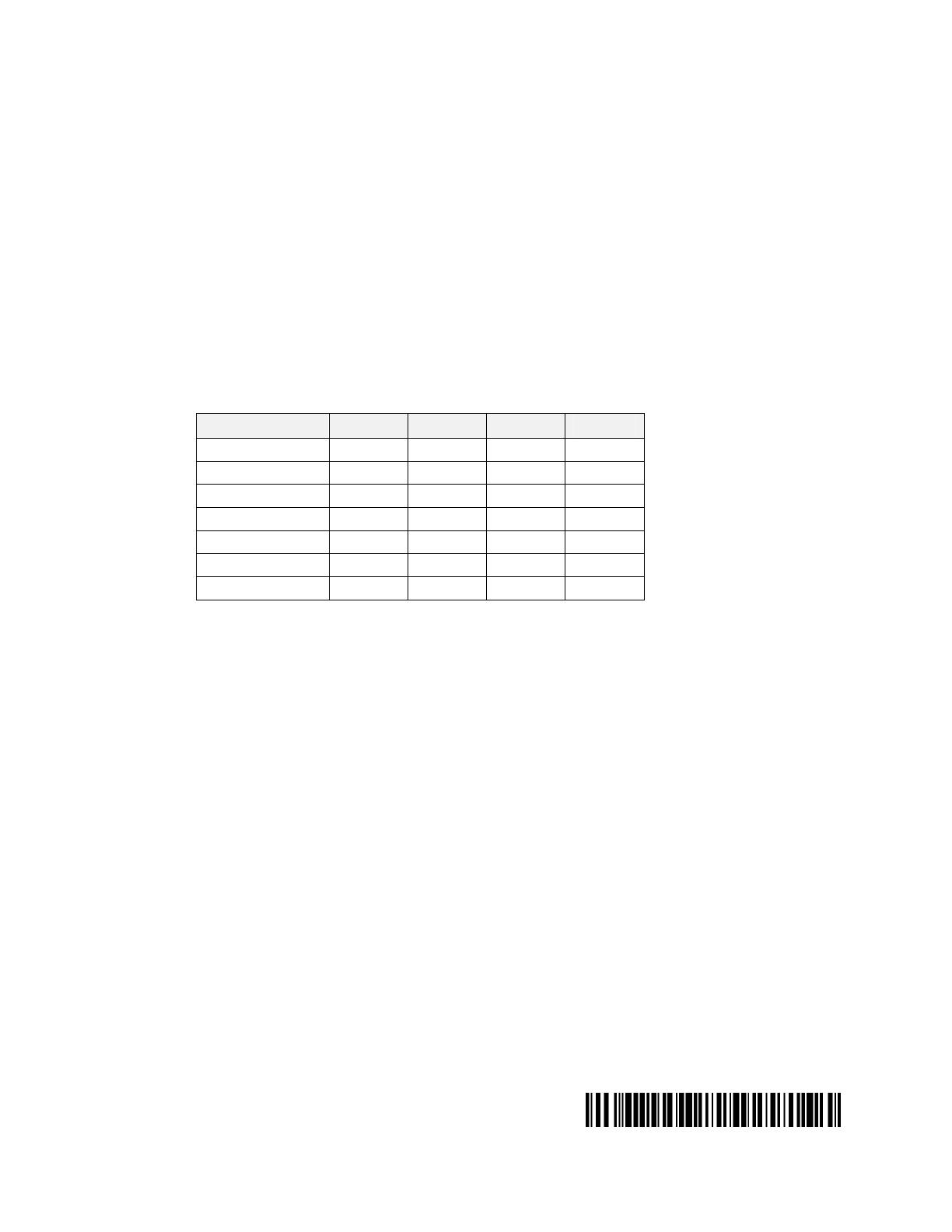
c) Highlight one of the Light Power values and press the A1 button to select it. The Light Power
values used depend on the light model, as shown in Table 1.
Table 1: Light Power Values Used by Each Light Model
Light 0 1 2 3
Back Light
Yes Yes Yes Yes
Dark Field Light
Yes Yes Yes Yes
Dome Light
Yes Yes Yes Yes
Linear Array
Yes Yes Yes No
On-Axis Diffuse
Yes Yes Yes Yes
Ring Light
Yes Yes Yes No
Spot Light
No No Yes Yes
d) Press the A4 button to set the Light Power parameter to 255. (The valid range is 0 through
255, where 0 is OFF and 255 is full intensity.)
e) Press the A1 button to accept the new value, and press OK to close the property sheet.
f) Press the Trigger button to acquire a new image.
g) Inspect the light. The installation is correct if one bank of LEDs is illuminated. Unlit banks of
LEDs correspond to Light Power values still set to zero. You can supply power to the unlit
LEDs by setting the corresponding Light Power value to 255 and then acquiring a new image.
9. To prevent strain on the connectors, fasten the cables at secure points near the In-Sight
processor and lights, allowing some slack between the fasteners and connectors.
To obtain Cognex lights, light cables, or other lighting accessories, contact your local Cognex sales
engineer.
  • Page 1 1
  • Page 2 2

Cognex In-Sight 2000 Installation guide

Type
Installation guide

Cognex In-Sight 2000 is a powerful vision sensor that combines industrial-grade image acquisition and processing with easy-to-use software tools. With its compact size, flexible lighting options, and intuitive user interface, the In-Sight 2000 is ideal for a wide range of applications, including:

  • Assembly verification
  • Part inspection
  • Robot guidance
  • Gauging
  • Measurement

The In-Sight 2000 is equipped with a high-resolution camera, a powerful processor, and a variety of lighting options to ensure accurate and reliable inspections.

Ask a question and I''ll find the answer in the document

Finding information in a document is now easier with AI