Follett 7UC100A User manual

Category
Ice cube makers
Type
User manual

This manual is also suitable for

Installation and Service Videos:
www.follettice.com/servicevideolibrary
00966879R11
801 Church Lane • Easton, PA 18040, USA
Toll free (877) 612-5086 • +1 (610) 252-7301
www.follettice.com
Installation, Operation and Service Manual
Serial numbers K39469 to K46456
Undercounter Ice and Water Dispenser
with Chewblet
®
Ice Machine
7UC100A, 7UD100A
7UC100A 7UD100A
Welcome to Follett
Follett equipment enjoys a well-deserved reputation for excellent performance, long-term reliability and outstanding
after-the-sale support. To ensure that this equipment delivers that same degree of service, review this guide
carefully before you begin your installation.
Should you need technical help, please call our Technical Service group at (877) 612-5086 or (610) 252-7301.
Please have your model number, serial number and complete and detailed explanation of the problem when
contacting Technical Service.
Getting Started
After uncrating and removing all packing material, inspect the equipment for concealed shipping damage. All freight
is to be inspected upon delivery. If visible signs of damage exist, please refuse delivery or sign your delivery receipt
"damaged." Follett Customer Service must be notied within 48 hours. Wherever possible, please include detailed
photos of the damage with the original packaging so that we may start the freight claim process.
2 Undercounter Dispenser and Ice Machine 7UC100A/7UD100A
Undercounter Dispenser and Ice Machine 7UC100A/7UD100A 3
Contents
Welcome to Follett. . . . . . . . . . . . . . . . . . . . . . . . . . . . . . . . . . . . . . . . . . . . . . . . . . . . . . . . . . . . . . . . . . . . . . . . . . . . . 1
Getting Started .............................................................................1
Before You Begin .............................................................................. 4
Important Safety Information .................................................................... 4
Specications ................................................................................5
Dimensions ................................................................................5
Ambient Information .........................................................................5
Plumbing .................................................................................. 5
Water ....................................................................................5
Clearances ................................................................................5
Electrical ..................................................................................5
Refrigeration ...............................................................................5
Heat Rejection .............................................................................5
Detailed Drawing ...........................................................................6
Installation ...................................................................................7
Maintenance/Cleaning Mode ....................................................................9
Accessing Internal Components .................................................................9
Filter Display Indicator Activation ............................................................... 10
Cleaning and Sanitizing Procedure .............................................................. 11
Service .....................................................................................12
LED Indicator Description ....................................................................12
Evaporator Disassembly ..................................................................... 13
Evaporator Assembly ....................................................................... 16
Water Feed Schematic ......................................................................20
Bin Melt Water/Evaporator Feed/Clean Out System Schematic ......................................21
Vent System Schematic .....................................................................21
Refrigeration Schematic .....................................................................22
Condenser Fan Motor Removal ...............................................................23
User Interface Display Identication ............................................................24
Electrical Wiring Diagram ....................................................................25
Exterior ..................................................................................26
Interior ................................................................................... 28
Bin Assembly .............................................................................30
Evaporator Assembly .......................................................................32
4 Undercounter Dispenser and Ice Machine 7UC100A/7UD100A
Before You Begin
If needed, the serial number of your dispenser can be found by removing the drip tray and locating the serial
number label . A QR Code is located on the right hand side of the drip tray . This code allows you to access
manuals, technical bulletins, and on-line training related to the 7 Series dispensers.
2
1
Scan to access technical
documentation or visit
www.follettice.com/7seriesdocs
00981100R00
3
Check your paperwork to verify that you received the correct dispenser. Follett conguration numbers are designed
to provide information about the type of dispenser you are receiving. The following is an explanation of the different
model numbers.
7 UC 100 A
Dispenser Storage
Capacity
Conguration Ice machine Capacity Condenser
7 lb UC Undercounter
UD Undercounter - ADA
100 lb per day A Air-cooled
Important Safety Information
Please read and adhere to the following safety information while installing, using, or servicing your Follett 7 Series
Ice Dispenser.
1. Always disconnect power before servicing the dispenser.
2. Ice is slippery. Maintain counters and oors around dispenser in a clean and ice-free condition.
3. Ice is food. Follow the recommended cleaning and sanitizing instructions to maintain cleanliness of
delivered ice.
Undercounter Dispenser and Ice Machine 7UC100A/7UD100A 5
Specications
Dimensions
7UC100A 7UD100A
Width 14.55" (370 mm) 14.55" (370 mm)
Depth 22.05" (560 mm) 22.05" (560 mm)
Height 33.50" (851 mm) 31.50" (800 mm)
Unit Shipping Weight 110 lb (50 kg) 110 lb (50 kg)
Ambient Information
CAUTION!
The 7UC100A and 7UD100A are for indoor use only.
Maximum* Minimum*
Air Temperature
100 F (38 C) 50 F (10 C)
Water Temperature 90 F (32.2 C) 40 F (4.5 C)
Water Pressure 70 psi 10 psi
Relative Humidity 55% at 78 F (25.5 C)
* Use outside of these limitations is misuse and will void warranty.
† Best performance is achieved between 80 F (27 C) and 50 F (10 C).
Plumbing
§ Water Inlet: 1/4" MPT
§ Optional Drain Accessory Kit (item# 00956375 or 00981977): 1/2" ID tubing
§ Water shut-off recommended within 5 ft (1.5 m) of dispenser
Water
WARNING!
Connect to potable water supply only.
§ Water Mineral Content:
TDS: greater than 5 ppm (mg/l) but less than 400 ppm (mg/l)
Hardness: Less than 200 mg/l (12 gpg)
§ Not recommended for use with softened water
Clearances
§ 3" (7.62 cm) behind dispenser for electrical and optional drain connection.
§ 6" (15.3 cm) in front of dispenser for ventilation.
Electrical
§ 115V, 60 Hz, 1 phase, 5A, maximum fuse 15A
§ Connect to dedicated 15A circuit, fuse or breaker
§ Must be grounded - requires 3-prong outlet. Do not remove ground.
Refrigeration
WARNING!
Do not damage the refrigerant circuit. Refrigerant can cause personal injury and/or damage dispenser.
§ Refrigerant R134a – 5.0 ounces (142 grams)
Heat Rejection
§ 1700 BTU/hr (498 W)
6 Undercounter Dispenser and Ice Machine 7UC100A/7UD100A
Detailed Drawing
A
A
C
B
7UC100A 7UD100A (ADA)
A
B
C
G
L2
L1
1/4" MPT
water inlet
SIDE VIEW
BACK VIEW
FRONT VIEW
Dimension
33.50" (85.1 cm)
22.76" (57.8 cm)
22.69" (57.6 cm)
31.50" (80 cm)
20.76" (52.7 cm)
20.69" (52.6 cm)
14.55" (37 cm)
22.05" (56 cm)
14.55" (37 cm)
2.40"
(6.1 cm)
2.98"
(7.6 cm)
3.81"
(9.7 cm)
4.00"
(10.2 cm)
NEMA 5-15
right angle
power cord
Undercounter Dispenser and Ice Machine 7UC100A/7UD100A 7
Installation
CAUTION!
No service or maintenance should be performed until the technician has thoroughly read this service
manual. Except for routine cleaning and sanitizing, only qualied technicians should attempt to service
or maintain this equipment.
1. Measure to verify that the dispenser will t in the desired location. A
clearance of at least 3" (7.62 cm) is required behind the dispenser
for the electrical and optional drain connection.
2. Ensure that the nished oor inside the cabinet is ush (level) with
the oor outside the cabinet (Fig. 1). If the cabinet oor is lower
than the nished oor, the cabinet oor must be built up (using
appropriate materials) until it is ush with the nished oor. A ush
oor is required for proper operation and maintenance/service of the
dispenser.
3. Rough-in the electrical service, water line, and optional Drip Tray
Drain Kit*.
Note: The dispenser must be installed such that it can be moved
forward at least 4" (10.2 cm) to allow access to the Bin Lid
Cleaning Spout (Fig. 9.6) for dispenser cleaning and sanitizing.
Take this requirement into consideration during rough-in.
§ Electrical: 115 V, single phase, 15A receptacle required. The dispenser
has an integral 8 ft (2.4 m) cord and plug.
§ Water: supply line (with shut-off valve) connects to the dispenser's
1/4" MPT inlet.
* The optional Drip Tray Drain Kit (item# 00956375) requires a oor drain
within 15 ft (4.5 m) of the dispenser. For detailed installation instructions,
please refer to the instructions shipped with the Drip Tray Drain Kit.
Fig. 1
floor
cabinet space
4. Install the angle bracket inside the cabinet,18.15" (46.1cm) from the
toe kick (Fig. 2.1). The bracket prevents the dispenser from being
located/pushed beyond the recommended cabinet space depth. Do
not attach the bracket to the dispenser.
Fig. 2
1
18.15” (46.1 cm)
8 Undercounter Dispenser and Ice Machine 7UC100A/7UD100A
5. Connect water line. Recommended routing (Fig. 3) allows easy access
to water for cleaning and sanitizing procedure.
Fig. 3
6. If installing the optional internal water lter*, please complete the
steps shown in Cleaning and Sanitizing Procedure on page 11
before proceeding. If not, proceed to step 10.
* If your dispenser has the internal water lter option, the water lter must be
installed for the dispenser to operate. Because internal components will need to
be accessed for both procedures, Follett recommends installing the water lter
just prior to initial sanitizing.
7. Lift and remove the top panel, set aside (Fig. 4.1).
8. Remove two screws (Fig. 4.2) and remove left side panel.
9. Install lter as shown. Turn lter clockwise until it is fully seated
(Fig.4.3).
10. Connect power supply.
11. Sanitize the dispenser prior to use (see Cleaning and Sanitizing
Procedure on page 11).
Fig. 4
1
2
3
1/4" MPT
3' (91.4 cm)
Plug
Valve
Undercounter Dispenser and Ice Machine 7UC100A/7UD100A 9
Maintenance/Cleaning Mode
Cleaning Mode (Dispensing Disabled) - Use when cleaning surface
Entering Cleaning Mode disables the User Interface and allows you to clean
the outside of the dispenser without accidentally dispensing water or ice.
1. To enter Cleaning Mode, press and immediately release the
maintenance/clean switch (Fig. 5.1) so that only "FRESH
FILTERED ICE AND WATER" displays in the user interface
(Fig.5.2).
2. To exit Cleaning Mode, press and immediately release the
maintenance/clean switch so that the ice and water icons also
display in the user interface.
Maintenance Mode (All Operation Disabled) - Use when cleaning ice
machine
Entering Maintenance Mode disables all operations and allows you to safely
clean and/or sanitize the ice machine and dispenser.
1. To enter Maintenance Mode, press and hold the maintenance/clean
switch (Fig. 5.3) until
displays in the user interface (Fig.5.4).
2. To exit Maintenance Mode, press and hold the maintenance/clean
switch until no longer displays in the user interface.
Note: Entering and exiting Maintenance Mode will reset the six-month
periodic maintenance reminder.
Fig. 5
4
3
2
1
Accessing Internal Components
CAUTION!
Except for routine cleaning and sanitizing, only qualied
technicians should attempt to service or maintain this equipment.
1. Press and hold the maintenance/clean switch (Fig. 5.1) until
displays in the user interface (Fig. 5.2).
2. Remove (unscrew) chrome ice dispenser chute (Fig. 6.1).
3. Remove the drip tray (Fig. 6.2).
4. Remove the two screws (Fig. 6.3) on the front panel (behind the
drip tray).
5. Remove and set aside the front panel (Fig. 6.4). Do not disengage
the plug on the back of the User Interface or the tubing at the
water dispenser chute (if so equipped).
Fig. 6
1
2
3
4
10 Undercounter Dispenser and Ice Machine 7UC100A/7UD100A
Filter Display Indicator Activation
If you purchased your dispenser with a Follett lter, the lter display indicator
activation has been preset at the factory.
If you are using an “after market lter,” an adjustment may be made to
activate the “Fresh Filtered Ice & Water” display.
Activating “Fresh Filtered Ice & Water”
1. Remove the front panel as explained in Accessing Internal
Components on page 9 then refer to Fig. 7.
2. Remove top panel (Fig. 7.1).
3. Remove (1) screw and top of control board enclosure (Fig. 7.2).
4. Locate the DIP switches on the dispenser's control board (Fig. 8).
Use a ne-pointed object to move the “Filter” DIP switch (DIP switch
#3) to the ON position.
Deactivating the Six-Month Maintenance/Filter Change Reminder
1. Use a ne-pointed object to move the “PM” DIP switch (DIP switch
#8) to the ON position.
Fig. 7
1
2
Ice and water
Internal filter supplied or to display "Fresh Filtered"
30 minute delay
Six-month PM disabled
OFF ON
Not used (OFF position)
Ice only
No internal filter
Not used (OFF position)
15 minute delay
Not used (OFF position)
Six-month PM enabled
1 2 3 4 5 6 7 8
Fig. 8
Undercounter Dispenser and Ice Machine 7UC100A/7UD100A 11
Cleaning and Sanitizing Procedure
Cleaning and sanitizing should be performed at least every 6 months (more often if
local water conditions dictate). For initial startup, only sanitizing is required.
IMPORTANT! Prior to cleaning and sanitizing, the dispenser must be moved
forward at least 4" (10.2 cm). Do not remove the Bin Lid, cleaning and sanitizing
solution is added through the Bin Lid Access Spout (Fig. 9.6).
WARNING!
§ Place the dispenser in Maintenance Mode prior to servicing or
cleaning the ice machine. See Maintenance/Cleaning Mode on page
9.
§ For protection, rubber gloves and safety goggles (and/or face shield)
should be worn when handling SafeCLEAN Plus™.
§ Do not use bleach, it will damage the dispenser.
Required Supplies
§ 7 Series
: Follow the directions on the SafeCLEAN Plus packaging to mix
3 gal (11.4 L) of Follett SafeCLEAN Plus solution. Use 100 F (38 C) water.
15 Series
: Follow the directions on the SafeCLEAN Plus packaging to mix
6 gal (22.7 L) of Follett SafeCLEAN Plus solution. Use 100 F (38 C) water.
§ Funnel, bucket,
100 F (38 C
) potable water
Ice machine and Dispenser
1. Dispense all the ice out of the unit.
2. Press and hold maintenance/clean switch until displays in the user
interface to enter Maintenance Mode.
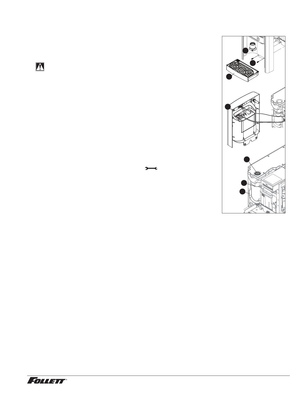
3. Remove (unscrew) chrome ice dispense chute (Fig. 9.1).
4. Remove drip tray (Fig. 9.2).
5. Remove (2) screws located behind the drip tray (Fig. 9.3).
6. Move front panel and place on top or beside unit (Fig. 9.4).
7. Remove plug cap from the end of drain tube (Fig. 9.5) and lower tube to
drain water into bucket. After the system has been drained of water replace
plug cap in drain tube.
Fig. 9
1
2
3
4
6
5
7
8. Secure tube in holder.
9. Remove cap from bin lid cover (Fig. 9.6).
10. Screw bin lid cover cap onto ice discharge chute (Fig. 9.7).
11. Pour SafeCLEAN Plus solution into bin lid access spout until solution reaches the spout neck.
12. Allow the SafeCLEAN Plus solution to remain in unit for 15 minutes.
13. While machine is cleaning, remove top and right side panel to access and clean air-cooled condenser.
14. Submerge ice dispense chute in the remainder of SafeCLEAN Plus solution for 2 minutes. Rinse with
clean, potable water.
15. Drain system by lowering drain tube into bucket.
16. Secure drain tube into holder.
1 7. Fill and drain twice with potable water. Secure drain tube.
18. Place a bucket under the dispense chute and remove cap. Note: Some SafeCLEAN Plus solution will
remain and drain out when cap is removed. Reposition cap on bin lid spout.
19. Reinstall front panel, ice dispense chute, and drip tray.
20. Press and hold maintenance/clean switch to exit Maintenance Mode.
12 Undercounter Dispenser and Ice Machine 7UC100A/7UD100A
User Interface and Exterior Cabinet
1. Press and release maintenance/clean switch so that only "FRESH FILTERED ICE AND WATER" displays
in the user interface to enter Cleaning Mode (and disable dispensing).
2. Plastic parts, including the user interface, can be cleaned with a non-abrasive glass cleaner. Clean
stainless steel panels with stainless steel cleaner.
3. Press and release maintenance/clean switch to put unit back into service.
Service
LED Indicator Description
The LED Indicator is located behind the front panel.
Fig. 10
Clean
PM
Drip tray
Water leak
HI press
HI amps
Service
Maint
Low water
Time delay
Sleep cycle
Making ice
Low bin
Power ON
LED Name LED Color Description
Clean Green The dispenser is in Cleaning Mode. Dispenser is disabled to allow for cleaning of front
panel. See Maintenance/Cleaning Mode on page 9.
N/A Not used.
PM Red Six-month periodic maintenance required.
Drip tray Red Drip tray full.
Water leak Red Internal leak in dispenser.
High amps Red Auger gearmotor has exceeded 0.55A. The HI amps and Time delay LEDs will illuminate,
the machine will shut down for one hour, the LEDs will turn off, and the machine will
resume normal operation.
Service Red 8000 hour bushing check (call Follett technical service group at (877) 612-5086 or
+1 (610) 252-7301).
Maintenance Yellow Enter Maintenance Mode by pressing and holding maintenance/clean switch for 5 seconds.
Unit will not make or dispense ice.
Low water Yellow Insufficient water supply to machine or no low bin LED upon startup.
Time delay Yellow Ice production will not resume for at least 15 minutes after a full bin is achieved and a
minimum amount of dispense activity has elapsed.
Sleep cycle Green After a full bin and 10 minutes of non-use, the unit goes into standby and will not produce
ice until either 12 hours has elapsed or ice or water has dispensed.
Making ice Green Gearmotor, compressor, and fan motor energized.
Low bin Green Bin switch closed calling for ice.
Power on Green Power supplied to unit.
Undercounter Dispenser and Ice Machine 7UC100A/7UD100A 13
Evaporator Disassembly
1. Disconnect power from the dispenser.
2. Turn off water supply to dispenser.
3. Remove (unscrew) chrome ice dispenser chute (Fig.11.1).
4. Remove the drip tray (Fig. 11.2).
5. Remove the two screws (Fig. 11.3) on the front panel
(behind the drip tray).
6. Remove and set aside the front panel (Fig. 11.4). Do not
disengage the plug on the back of the User Interface.
7. Lift and remove the top panel, set aside (Fig.16.5).
8. Remove two screws (Fig. 11.6) and remove left side panel.
9. Remove two screws (Fig. 11.7) and remove right side
panel.
Fig. 11
2
1
3
4
5
6
2
1
7
14 Undercounter Dispenser and Ice Machine 7UC100A/7UD100A
10. Unplug the gear motor (three connectors) (Fig.12).
11. Remove ground screw connection.
Fig. 12
12. Remove gear motor:
§ Remove M6 allen screw, retainer, spacer and key (Fig. 13.1).
§ Remove two M6x90 allen screws (Fig. 13.2).
§ Pull gear motor from auger (Fig. 13.3).
§ Remove main housing insulation (Fig. 13.4).
13. Remove all traces of Petrol-gel from auger shaft.
Fig. 13
2
2
1
3
4
14. Remove compression nozzle:
§ Loosen hose clamp (Fig.14.1).
§ Remove transport tube (Fig. 14.2).
Fig. 14
1
2
Undercounter Dispenser and Ice Machine 7UC100A/7UD100A 15
15. Remove M6 socket head allen screw (Fig.15.1).
16. Remove compression nozzle retainer (Fig. 15.2).
1 7. Remove compression nozzle (Fig. 15.3).
Fig. 15
2
1
3
18. Remove main housing:
§ Disconnect vent line from T tting (Fig.16.1).
Fig. 16
1
19. Remove three M6x25 socket head allen screws
(Fig.17.1).
20. Remove main housing (Fig. 17.2).
Fig. 17
1
2
16 Undercounter Dispenser and Ice Machine 7UC100A/7UD100A
2 1. Remove and discard mating ring and seal (Fig.18.1).
22. Carefully remove auger (Fig. 18.2).
WARNING!
Use caution when removing auger. The auger is very
sharp - handle with care to avoid personal injury.
Fig. 18
1
2
Evaporator Assembly
1. Remove and inspect main housing O-ring seal. Replace if
damaged in any way.
2. Clean O-ring groove. Lubricate O-ring with Petrol-gel and
reinstall.
3. Use cardboard disc to press new mating ring into main
housing (Fig. 19.1).
4. Lube the shaft with liquid soap in the area shown
(Fig.19.2) and slip on seal and spring (Fig. 19.3).
Note: Do not touch the sealing surfaces with bare hands.
Contact with bare skin will cause premature seal failure.
5. Install auger (Fig. 19.4).
Fig. 19
Cardboard
disc
Do NOT
touch!
1
3
4
2
6. Install main housing:
§ Slide main housing onto auger shaft (Fig.20.1).
§ Install three M6x25 allen screws (Fig.20.1).
§ Connect vent line to T tting (Fig.20.1).
Fig. 20
1
2
3
Undercounter Dispenser and Ice Machine 7UC100A/7UD100A 17
7. Install compression nozzle:
§ Remove and inspect compression nozzle O-ring seal.
Replace if damaged in any way.
§ Clean O-ring groove. Lubricate O-ring with Petrol-gel and
reinstall.
§ Install compression nozzle (Fig.21.1).
§ Install compression nozzle retainer (Fig.21.2).
§ Install M6 socket head allen screw (Fig.21.3).
Fig. 21
2
1
3
8. Install transport tube (Fig. 22.1).
9. Tighten hose clamp (Fig.22.2).
Fig. 22
2
1
10. Install gear motor:
§ Install main housing insulation (Fig.23.1).
§ Slide gear motor onto auger shaft (Fig.23.2).
§ Install two M6x90 allen screws (Fig. 23.3).
Fig. 23
3
3
2
1
18 Undercounter Dispenser and Ice Machine 7UC100A/7UD100A
11. Use screwdriver to orient auger shaft to align with motor
shaft keyway (Fig. 24.1).
12. Install key into keyway (Fig. 24.2).
Fig. 24
1
2
3
13. Install spacer, ensure that key is captured in slot
(Fig.25.1)
Fig. 25
1
Undercounter Dispenser and Ice Machine 7UC100A/7UD100A 19
14. Insert screwdriver into groove of auger shaft and pry shaft
outwards (Fig.26.1).
15. Insert retainer into groove (Fig.26.2), ensure that retainer
is aligned with hole in spacer.
Fig. 26
1
2
16. Install screw and tighten (Fig.27.1). Fig. 27
1
2
20 Undercounter Dispenser and Ice Machine 7UC100A/7UD100A
1 7. Plug in gear motor (Fig.28).
§ BLUE to BLUE
§ BLACK to BLACK
§ WHITE to WHITE
§ Connect ground wire with ground screw.
Fig. 28
BLUE to BLUE
BLACK to BLACK
WHITE to WHITE
Water Feed Schematic
Water Solenoid Valve
(optional)
Filter (optional)
Water Solenoid Valve
Water Chute
(optional)
Evaporator
Float
  • Page 1 1
  • Page 2 2
  • Page 3 3
  • Page 4 4
  • Page 5 5
  • Page 6 6
  • Page 7 7
  • Page 8 8
  • Page 9 9
  • Page 10 10
  • Page 11 11
  • Page 12 12
  • Page 13 13
  • Page 14 14
  • Page 15 15
  • Page 16 16
  • Page 17 17
  • Page 18 18
  • Page 19 19
  • Page 20 20
  • Page 21 21
  • Page 22 22
  • Page 23 23
  • Page 24 24
  • Page 25 25
  • Page 26 26
  • Page 27 27
  • Page 28 28
  • Page 29 29
  • Page 30 30
  • Page 31 31
  • Page 32 32
  • Page 33 33
  • Page 34 34
  • Page 35 35
  • Page 36 36

Follett 7UC100A User manual

Category
Ice cube makers
Type
User manual
This manual is also suitable for

Ask a question and I''ll find the answer in the document

Finding information in a document is now easier with AI