Page is loading ...

SC213 ChaSSiS SerieS
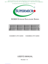
SC213AC-R1K23LPB SC213AC-R1K23WB
SC213AC-R920LPB SC213AC-R920WB
SC213A-R740LPB SC213A-R740WB
SC213A-R720LPB SC213A-R720UB
SC213A-R900LPB SC213A-R900UB
USer’S MaNUaL
1.0c

Manual Revision 1.0c
Release Date: March 06, 2017
The information in this User’s Manual has been carefully reviewed and is believed to be accurate.
The vendor assumes no responsibility for any inaccuracies that may be contained in this document,
makes no commitment to update or to keep current the information in this manual, or to notify any
person or organization of the updates. Please Note: For the most up-to-date version of this
manual, please see our web site at www.supermicro.com.
Super Micro Computer, Inc. ("Supermicro") reserves the right to make changes to the product
described in this manual at any time and without notice. This product, including software and
documentation, is the property of Supermicro and/or its licensors, and is supplied only under a
license. Any use or reproduction of this product is not allowed, except as expressly permitted by
the terms of said license.
IN NO EVENT WILL SUPERMICRO BE LIABLE FOR DIRECT, INDIRECT, SPECIAL, INCIDENTAL,
SPECULATIVE OR CONSEQUENTIAL DAMAGES ARISING FROM THE USE OR INABILITY TO
USE THIS PRODUCT OR DOCUMENTATION, EVEN IF ADVISED OF THE POSSIBILITY OF
SUCH DAMAGES. IN PARTICULAR, SUPERMICRO SHALL NOT HAVE LIABILITY FOR ANY
HARDWARE, SOFTWARE, OR DATA STORED OR USED WITH THE PRODUCT, INCLUDING THE
COSTS OF REPAIRING, REPLACING, INTEGRATING, INSTALLING OR RECOVERING SUCH
HARDWARE, SOFTWARE, OR DATA.
Any disputes arising between manufacturer and customer shall be governed by the laws of Santa
Clara County in the State of California, USA. The State of California, County of Santa Clara shall
be the exclusive venue for the resolution of any such disputes. Super Micro's total liability for
all claims will not exceed the price paid for the hardware product.
California Best Management Practices Regulations for Perchlorate Materials: This Perchlorate
warning applies only to products containing CR (Manganese Dioxide) Lithium coin cells. “Perchlorate
Material-special handling may apply. See www.dtsc.ca.gov/hazardouswaste/perchlorate”
WARNING: Handling of lead solder materials used in this
product may expose you to lead, a chemical known to
the State of California to cause birth defects and other
reproductive harm.
Unless you request and receive written permission from Super Micro Computer, Inc., you may not
copy any part of this document.
Information in this document is subject to change without notice. Other products and companies
referred to herein are trademarks or registered trademarks of their respective companies or mark
holders.
Copyright © 2017 by Super Micro Computer, Inc.
All rights reserved.
Printed in the United States of America

iii
Preface
Preface
About this Manual
This manual is written for professional system integrators and PC technicians. It
provides information for the installation and use of the chassis. Installation and
maintenance should be performed by experienced technicians only.
This document lists compatible parts available when this document was published.
Refer to the Supermicro web site for updates on supported parts and congurations.
Warnings
Special attention should be given to the following symbols used in this manual.
Warning! Indicates high voltage may be encountered when performing
a procedure.
Warning! Indicates important information given to prevent equipment/
property damage or personal injury.

SC213 Chassis Manual
iv
Contents
Chapter 1 Introduction
1-1 Overview ......................................................................................................... 1-1
1-2 Shipping List .................................................................................................... 1-2
1-3 Chassis Features ............................................................................................ 1-2
Motherboard Support ...................................................................................... 1-2
Drives .............................................................................................................. 1-2
PCI Expansion Slots ....................................................................................... 1-2
Cooling ............................................................................................................ 1-2
Control Panel .................................................................................................. 1-2
Cables ............................................................................................................. 1-2
1-4 Returning Merchandise for Service................................................................. 1-3
1-5 Where to Get Replacement Components ....................................................... 1-3
Chapter 2 Rack Installation
2-1 Unpacking the System .................................................................................... 2-1
2-2 Preparing for Setup ......................................................................................... 2-1
Choosing a Setup Location ............................................................................. 2-1
2-3 Warnings and Precautions .............................................................................. 2-2
Rack Precautions ............................................................................................ 2-2
General Server Precautions ............................................................................ 2-2
Rack Mounting Considerations ....................................................................... 2-3
Ambient Operating Temperature ................................................................ 2-3
Sufcient Airow ......................................................................................... 2-3
Circuit Overloading ..................................................................................... 2-3
Reliable Ground ......................................................................................... 2-3
2-4 Installing the System into a Rack .................................................................. 2-4
Identifying the Sections of the Rack Rails ...................................................... 2-4
Releasing the Inner Rail ................................................................................. 2-5
Installing the Inner Rails on the Chassis ........................................................ 2-6
Installing the Outer Rails onto the Rack ......................................................... 2-7
Sliding the Chassis onto the Rack Rails ......................................................... 2-8
Chapter 3 System Interface
3-1 Overview ......................................................................................................... 3-1
3-2 Control Panel Buttons ..................................................................................... 3-2
Power .............................................................................................................. 3-2
Reset ............................................................................................................... 3-2

v
Preface
3-3 Control Panel LEDs ........................................................................................ 3-2
Power .............................................................................................................. 3-2
HDD ................................................................................................................. 3-2
NIC2 ................................................................................................................ 3-3
NIC1 ................................................................................................................ 3-3
Information LED .............................................................................................. 3-3
Power Fail ....................................................................................................... 3-3
Overheating ..................................................................................................... 3-4
3-4 Drive Carrier LEDs .......................................................................................... 3-4
3-5 Power Supply LEDs ........................................................................................ 3-5
Chapter 4 Chassis Setup and Maintenance
4-1 Overview ......................................................................................................... 4-1
4-2 Removing Power from the System ................................................................. 4-2
4-3 Removing the Chassis Cover ......................................................................... 4-3
4-4 Installing Hard Drives ...................................................................................... 4-4
4-5 Installing Expansion Cards ............................................................................. 4-6
Expansion Cards for an LP Model Chassis .................................................... 4-6
Expansion Cards for a W or U Model Chassis ............................................... 4-6
4-6 Installing the Air Shroud .................................................................................. 4-9
4-7 Power Supply .................................................................................................4-11
4-8 Installing the Power Distributor ..................................................................... 4-12
4-9 Removing the Backplane .............................................................................. 4-13
Appendix A SC213 Power Supply Specications
Appendix B Standardized Warning Statements for AC Systems
Appendix C BPN-SAS-213A Backplane Specications
Appendix D BPN-SAS3-213A Backplane Specications

Contacting Supermicro
Headquarters
Address: Super Micro Computer, Inc.
980 Rock Ave.
San Jose, CA 95131 U.S.A.
Tel: +1 (408) 503-8000
Fax: +1 (408) 503-8008
Email: [email protected] (General Information)
[email protected] (Technical Support)
Web Site: www.supermicro.com
Europe
Address: Super Micro Computer B.V.
Het Sterrenbeeld 28, 5215 ML
's-Hertogenbosch, The Netherlands
Tel: +31 (0) 73-6400390
Fax: +31 (0) 73-6416525
Email: [email protected] (General Information)
[email protected] (Technical Support)
[email protected] (Customer Support)
Web Site: www.supermicro.nl
Asia-Pacic
Address: Super Micro Computer, Inc.
3F, No. 150, Jian 1st Rd.
Zhonghe Dist., New Taipei City 235
Taiwan (R.O.C)
Tel: +886-(2) 8226-3990
Fax: +886-(2) 8226-3992
Email: [email protected]
Web Site: www.supermicro.com.tw
SC213 Chassis Manual
vi

1-1
Chapter 1: Introduction
SC213 Chassis Series
Model HDD PCI Slots Power Supply
SC213AC-R1K23LPB
16x 2.5" hot-
swap SAS/SATA
7x LP 1200W (Redundant, Titanium)
SC213AC-R1K23WB
16x 2.5" hot-
swap SAS/SATA
4x FH &
3x LP
1200W (Redundant, Titanium)
SC213AC-R920LPB
16x 2.5" hot-
swap SAS/SATA
7x LP 920W (Redundant, Platinum)
SC213AC-R920WB
16x 2.5" hot-
swap SAS/SATA
4x FH &
3x LP
920W (Redundant, Platinum)
SC213A-R740LPB
16x 2.5" hot-
swap SAS/SATA
7x LP 740W (Redundant, Platinum)
SC213A-R740WB
16x 2.5" hot-
swap SAS/SATA
4x FH &
3x LP
740W (Redundant, Platinum)
SC213A-R720LPB
16x 2.5" hot-
swap SAS/SATA
7x LP 720W (Redundant, Gold)
SC213A-R720UB
16x 2.5" hot-
swap SAS/SATA
4x FH &
3x LP
720W (Redundant, Gold)
SC213A-R900LPB
16x 2.5" hot-
swap SAS/SATA
7x LP 900W (Redundant)
SC213A-R900UB
16x 2.5" hot-
swap SAS/SATA
4x FH &
3x LP
900W (Redundant)
Chapter 1
Introduction
1-1 Overview
The Supermicro SC213 chassis features a direct-attached SAS3 backplane
supporting sixteen 2.5" SAS/SATA hard disk drives. It has dual highly efcient
redundant power supplies, an optional DVD drive, two USB ports, three 80mm
fans, and room for seven PCI Express expansion cards.

SC213 Chassis Manual
1-2
1-2 Shipping List
Visit the Supermicro web site for the latest shipping lists and part numbers for
your particular chassis model at www.supermicro.com.
1-3 Chassis Features
The SC213 3U high-performance chassis includes the following features:
Motherboard Support
The chassis supports motherboard sizes of 13.68" x 13.0", E-ATX, ATX form factors.
It supports dual and single Intel and AMD processors.
Drives
The chassis supports up to sixteen 2.5" hot-swap SAS or SATA drives with SES2.
With RAID, these drives may be replaced without powering down the server. It also
supports one slim DVD drive (optional).
PCI Expansion Slots
Each version of the chassis includes seven slots with sizes depending on the model.
Cooling
Three hot-plug 80mm fans provide cooling, aided by an air shroud. The 4-pin fans
are controlled though IPMI.
Control Panel
The front control panel includes system status LED indicators and power switches.
Cables
To determine what cables are needed for your system, check the connector type
of your system backplane and motherboard. Then consult the Supermicro website.
https://www.supermicro.com/ResourceApps/Cable_Matrix.aspx

1-3
Chapter 1: Introduction
1-4 Returning Merchandise for Service
A receipt or copy of your invoice marked with the date of purchase is required before
any warranty service will be rendered. You can obtain service by calling your vendor
for a Returned Merchandise Authorization (RMA) number. When returning to the
manufacturer, the RMA number should be prominently displayed on the outside of
the shipping carton, and mailed prepaid or hand-carried. Shipping and handling
charges will be applied for all orders that must be mailed when service is complete.
For faster service, RMA authorizations may be requested online (http://www.
supermicro.com/support/rma/).
Whenever possible, repack the chassis in the original Supermicro carton, using the
original packaging material. If these are no longer available, be sure to pack the
chassis securely, using packaging material to surround the chassis so that it does
not shift within the carton and become damaged during shipping.
This warranty only covers normal consumer use and does not cover damages
incurred in shipping or from failure due to the alteration, misuse, abuse or improper
maintenance of products.
During the warranty period, contact your distributor rst for any product problems.
1-5 Where to Get Replacement Components
Although not frequently, you may need replacement parts for your system. To
ensure the highest level of professional service and technical support, we strongly
recommend purchasing exclusively from our Supermicro Authorized Distributors/
System Integrators/Resellers. A list of Supermicro Authorized Distributors/System
Integrators/Resellers can be found at: www.supermicro.com. Click the Where to
Buy link

SC213 Chassis Manual
1-4
Notes

2-1
Chapter 2 Rack Installation
Chapter 2
Rack Installation
This chapter provides instructions for preparing and mounting your chassis in a rack.
2-1 Unpacking the System
You should inspect the box the chassis was shipped in and note if it was damaged
in any way. If the chassis itself shows damage, le a damage claim with the carrier
who delivered it.
2-2 Preparing for Setup
Decide on a suitable location for the rack unit that will hold your chassis. It should
be a clean, dust-free area that is well ventilated. Avoid areas where heat, electrical
noise and electromagnetic elds are generated. A nearby grounded power outlet.
is required
The box your chassis was shipped in should include two sets of rail assemblies, two
rail mounting brackets and the mounting screws to mount the system into the rack.
Please read this chapter in its entirety before beginning the installation procedure.
Choosing a Setup Location
• Leave at least 25 inches clearance in front of the rack to open the front door
completely.
• Leave approximately 30 inches of clearance in the back of the rack to allow for
sufcient airow and access for servicing.
• It should be a restricted access location, such as a dedicated equipment room
or a service closet.

SC213 Chassis Manual
2-2
2-3 Warnings and Precautions
Rack Precautions
• Ensure that the leveling jacks on the bottom of the rack are fully extended to
the oor with the full weight of the rack resting on them.
• In single rack installations, stabilizers should be attached to the rack.
• In multiple rack installations, the racks should be coupled together.
• Always make sure that the rack is stable before extending a component from
the rack.
• Only one chassis should be extended from the rack at a time. Extending two or
more chassis simultaneously may cause the rack to become unstable.
General Server Precautions
• Review the electrical and general safety precautions that came with the
components you are adding to your chassis.
• Determine the placement of each component in the rack before you install the
rails.
• Install the heaviest server components on the bottom of the rack rst, and then
work upward.
• Use a regulating uninterruptible power supply (UPS) to protect the server from
power surges, voltage spikes and to keep your system operating in case of a
power failure.
• Allow the hot-swappable hard drives and power supply modules to cool before
touching them.
• Always keep the rack's front door and all panels and components on the servers
closed when not servicing to maintain proper cooling.

2-3
Chapter 2 Rack Installation
Rack Mounting Considerations
Ambient Operating Temperature
If installed in a closed or multi-unit rack assembly, the ambient operating
temperature of the rack environment may be greater than the ambient temperature
of the room. Therefore, consideration should be given to installing the equipment
in an environment compatible with the manufacturer’s maximum rated ambient
temperature (TMRA).
Sufcient Airow
Equipment should be mounted into a rack so that the amount of airow required
for safe operation is not compromised.
Circuit Overloading
Consideration should be given to the connection of the equipment to the power
supply circuitry and the effect that any possible overloading of circuits might have
on overcurrent protection and power supply wiring. Appropriate consideration of
equipment nameplate ratings should be used when addressing this concern.
Reliable Ground
A reliable ground must be maintained at all times. To ensure this, the rack
itself should be grounded. Particular attention should be given to power supply
connections other than the direct connections to the branch circuit (i.e. the use of
power strips, etc.).
Warning: To prevent bodily injury when mounting or servicing this unit in a
rack, you must take special precautions to ensure that the system remains
stable. The following guidelines are provided to ensure your safety:
• This unit should be mounted at the bottom of the rack if it is the only unit in
the rack.
• When mounting this unit in a partially lled rack, load the rack from the bottom
to the top with the heaviest component at the bottom of the rack.
• If the rack is provided with stabilizing devices, install the stabilizers before
mounting or servicing the unit in the rack.
• Slide rail mounted equipment is not to be used as a shelf or a work space.

SC213 Chassis Manual
2-4
2-4 Installing the System into a Rack
This section provides information on installing the server into a rack unit with the
rack rails provided. There are a variety of rack units on the market, so the assembly
procedure may differ slightly. Refer to the installation instructions that came with
your rack. Note: This rail will t a rack between 26.5" and 36.4" deep.
Identifying the Sections of the Rack Rails
The chassis package includes two rail assemblies. Each assembly consists of three
sections: An inner rail that secures directly to the chassis, an outer rail that secures
to the rack, and a middle rail which extends from the outer rail. These assemblies
are specically designed for the left and right side of the chassis.
Figure 2-1. Identifying the Outer Rail, Middle Rail and Inner Rail
(Left Rail Assembly Shown)
Inner Rail
Rail Assembly
(Shown with Rails
Retracted)
This Side Faces
Outward
Locking Tab
Middle Rail
Outer Rail

2-5
Chapter 2 Rack Installation
Figure 2-2. Extending and Releasing the Inner Rail
Releasing the Inner Rail
Each inner rail has a locking latch. This latch prevents the server from coming
completely out of the rack when when the chassis is pulled out for servicing.
To mount the rail onto the chassis, rst release the inner rail from the outer rails.
Releasing Inner Rail from the Outer Rails
1. Pull the inner rail out of the outer rail until it is fully extended as illustrated below.
2. Press the locking tab down to release the inner rail.
3. Pull the inner rail all the way out.
4. Repeat for the other outer rail.
1
1
1
2
1
3

SC213 Chassis Manual
2-6
1
3
1
4
1
4
1
2
Inner Rails
Figure 2-3. Installing the Inner Rails
Installing the Inner Rails on the Chassis
Installing the Inner Rails
1. Identify the left and right inner rails. They are labeled.
2. Place the inner rail rmly against the side of the chassis, aligning the hooks on
the side of the chassis with the holes in the inner rail.
3. Slide the inner rail forward toward the front of the chassis until the quick release
bracket snaps into place, securing the rail to the chassis.
4. Optionally, you can further secure the inner rail to the chassis with a screw.
5. Repeat for the other inner rail.
Figure 2-4. Inner Rails Installed on the Chassis

2-7
Chapter 2 Rack Installation
Figure 2-5. Extending and Mounting the Outer Rails
1
1
1
2
1
3
1
4
21D01
L-min=676.00(26.61")(outer rail)
Installing the Outer Rails onto the Rack
Installing the Outer Rails
1. Press upward on the locking tab at the rear end of the middle rail.
2. Push the middle rail back into the outer rail.
3. Hang the hooks on the front of the outer rail onto the square holes on the front
of the rack. If desired, use screws to secure the outer rails to the rack.
4. Pull out the rear of the outer rail, adjusting the length until it just ts within the
posts of the rack.
5. Hang the hooks of the rear section of the outer rail onto the square holes on the
rear of the rack. Take care that the proper holes are used so the rails are level.
If desired, use screws to secure the rear of the outer rail to the rear of the rack.
Stability hazard. The rack stabilizing mechanism must be in place, or the rack
must be bolted to the oor before you slide the unit out for servicing. Failure to
stabilize the rack can cause the rack to tip over.
Do not use a two post "telco" type rack.

SC213 Chassis Manual
2-8
Figure 2-6. Installing into a Rack
Ball-Bearing
Shuttle
Sliding the Chassis onto the Rack Rails
Warning: Mounting the system into the rack requires at least two people to
support the chassis during installation. Please follow safety recommendations
printed on the rails.
Installing the Chassis into a Rack
1. Extend the outer rails as illustrated above.
2. Align the inner rails of the chassis with the outer rails on the rack.
3. Slide the inner rails into the outer rails, keeping the pressure even on both
sides. When the chassis has been pushed completely into the rack, it should
click into the locked position.
4. Optional screws may be used to hold the front of the chassis to the rack.
Note: The gure above is for illustrative purposes only. Always install servers to
the bottom of the rack rst.
Caution: Do not pick up the server with the front handles. They are designed
to pull the system from a rack only.

Chapter 3: System Interface
3-1
Chapter 3
System Interface
3-1 Overview
The server includes a control panel on the front that houses power buttons and
status monitoring lights. The externally accessible hard drives display status lights.
The power supply displays status lights visible from the back of the chassis.
Figure 3-1. Front Control Panel

SC213 Chassis Manual
3-2
3-3 Control Panel LEDs
There are six LEDs that provide status information about the system.
Power
The main power switch applies or removes primary power from the power supply
to the server but maintains standby power. To perform most maintenance tasks,
unplug the system to remove all power..
Reset
The reset button is used to reboot the system.
3-2 Control Panel Buttons
The chassis includes two push-buttons that control power to the system.
Power
Indicates power is being supplied to the system power supply units. This LED is
illuminated when the system is operating normally.
HDD
Indicates activity on the hard disk drive when ashing.
/