Page is loading ...

- 1 -
!
!
PRODUCT INSTRUCTIONS
REVISION DATE: May 3, 2004
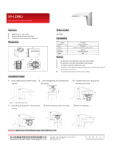
81-IN5310 RH7CS Rugged Dome
Series with unitized pan/tilt/zoom
DESCRIPTION:
The vandal resistant RH7CS Housing top is high impact resistant
cast aluminum; the lower dome is made of an optically clear, UV
stable, polycarbonate plastic. It measures 9.75” (w) x 13 (h) x 14.5”
(d) with a weight of 8.25 lbs. Flying leads are provided for all power,
control and video connections, with a standard BNC and (2) screw
down connectors. Two 25W heater (50 watts total) with (2) circulation
fans are also supplied.
ELECTRICAL SPECIFICATIONS (OUTDOOR ONLY):
Power 24VAC, Class 2 Only
52 watts at 24 VAC (accessories)
Heater: 50 watts
Blower: 2 watts
Input Connectors (outdoor units):
BNC, (2) screw-down connectors
NOTE: This unit is designed for operation in an upright
position. Installing the RH7 upside down may
cause damage to the internal equipment, and
will void the warranty.
PARTS LIST
Check to be sure the following parts are included in the box:
1. Housing
2. Housing Packet
a. (2) Mates for screw down connectors (not supplied with
indoor units)
b. (1) Adapter plate
c. (8) 1/2" standoffs
d. (8) 8 x 32 x 3/8" Mounting screws with star washers
e. (3) 6 x 32 x 3/8" Mounting screws with star washers
f. (2) 1/4 x 20 x 3/8" HH Bolts
g. (2) 1/4” Flat washers
h. (2) 1/4" Split Lock washers
i. Instruction Manual
Be sure the bracket is properly and securely mounted
to a supporting structure capable of rigidly holding the
weight of the entire unit.
INSTALLING QUICK RELEASE BRACKET AND
PAN/TILT CAMERA ASSEMBLY (ALL MODELS)
1. Open the housing by loosening the (3) tamper proof screws
located on the housing ring next to the lower clear dome
(Figure 1). Be careful not to back these all the way out. Twist the
dome slightly in a counterclockwise motion until it stops, then pull
down to remove.
Figure 1
Loosen screws only,
do not remove
Remove dome by
twisting coun ter -
clock wise until it
stops, then pull down
2. Install the pan/tilt unit quick- release bracket. It is recommended
that this be done before installing the housing. On the next
page are instructions for mounting quick-release brackets from
selected manufacturers.
GENERAL INSTRUCTIONS:
Tools Required: .100" Flat Head Screwdriver
Phillips Head Screwdriver
3. Clean the inside of the dome. Reattach the housing dome and
secure the (3) captive screws. Do not overtighten the screws.
Tighten only to the point at which the gap between the ring and
the housing top closes.
1. RH7CS
A wall mount bracket comes standard with this unit, and a tem-
plate is included to use as a guide for mounting the bracket to a
wall. Choose the desired location for installation and mark the drill
holes using the template. Screw (2) bolts (not provided) about 3/4
of the way into the (2) top holes. Run approximately 8" of wiring
out of the wall.
NOTE: Be sure the hardware and the mounting surface can sup-
port the weight of the wall mount bracket plus the weight
of the housing and drive unit. The load will be subjected
to vibration from the camera motor and wind.
INSTALLING THE HOUSING ASSEMBLY
FOR WALL MOUNT, RH7CS
TABLE OF CONTENTS
Description 1
Electrical Specifi cations 1
Parts List 1
Installing Quick Release Bracket 1
Installing the Housing Assembly 1
Installing Optional Pendant Mount 2
Wiring Color Code Chart 3
Wiring Distance Chart 3
Setting the Protocol 3
Setting the Address 3
Optional VLPT385 Settings 4
Pan/Tilt Address Dip Switch Settings 5
Exploded Views 8
Mounting Template 10
Safeguards and Warranty Info 11

- 2 -
Figure 4
Twist and
Secure
3. Mount the housing assembly to the mounting bracket and housing
coupling. A safety cable is included with the housing to
temporarily hold it while making wiring connections. Loop the
safety cable over one of the set screws on the housing coupling
and make the appropriate connections using the (2) screw-down
connectors supplied.
4. Undo the safety cable and twist the housing onto the housing
coupling. Secure all (3) setscrews provided on the housing
coupling (Figure 4).
4. Attach the wires from the wall to the connector provided, using the
wiring color code chart as a guide.
5. Once all wiring connections are made, place the wires inside the
wall mount bracket and close the access door. Secure with the
screw removed earlier.
6. Clean the outside of the dome.
Figure 2
Access
Door
5. Clean the outside of the dome.
The RH7CS is setup with (2) individual power inputs.
1. Accessory Power (yellow and green wire)
2. Camera Power (red and orange)
If you wish to provide a single power transformer it is recommended
that:
1. Be certain that you know the total power consumption of the hous-
ing Heaters (50 watts) + Blowers (2 watts) + camera/pan-tilt (not
supplied)
2. Check the supplied wiring chart to be sure that you have the
proper gauge wire for the distance that you intend to run your
power wires.
3. Bring power to the 3 and 4 position of the power connector (yellow
and green wire)
4. Two jumpers are provided in the housing packet. Jumper from the
1
st
position to the 3
rd
position and from the 2
nd
position to the 4
th
position of the terminal block. Be careful not to short between the
yellow and green wires.
Figure 5
Add 2 jumpers for
single power input
2. The wall mount bracket provided with the rugged housing includes
a location for conduit entry. If you wish to install conduit to the
bracket remove the conduit hole plug. Install fi tting from below the
wall mount and secure with conduit nut from inside the bracket.
3. Open the access door on the bottom of the wall mount by
loosening the screw nearest the mounting plate (Figure 2).
Figure 3
Add thread
sealing tape
FOR OPTIONAL PENDANT MOUNT
1. This unit includes a 1 1/2" NPT housing for a standard 1 1/2" NPT
pipe. The RH7CS can be used with other brackets designed with
1 1/2" male pipe threads, such as the Videolarm WM20G and
WM20 wall mount brackets.
2. Attach the housing coupling (Figure 3).
NOTE: Pipe threads should be clean and rust free. Use a
sealer (such as Tefl on™ tape or silicone sealer) on the
threads.

- 3 -
22
250
120
89
65
44
35
29
25
31
19
17
16
14
13
12
11
11
10
9
9
8
20
400
180
141
90
70
56
47
40
34
31
28
25
23
21
20
18
17
16
15
14
14
18
600
300
225
130
112
90
75
64
55
50
45
41
37
34
32
30
28
26
25
23
22
16
960
480
358
225
179
143
119
102
85
79
71
65
59
55
51
47
44
42
39
37
35
14
-
800
571
350
285
228
190
163
140
126
114
103
95
87
81
76
71
67
63
60
57
12
-
1300
905
525
452
362
301
258
215
201
181
164
150
139
129
120
113
106
100
95
90
10
-
-
1440
830
720
576
480
411
340
320
288
261
240
221
205
192
180
169
160
151
144
5.5
10
20
30
40
50
60
70
80
90
100
110
120
130
140
150
160
170
180
190
200
Maximum distance from transformer to load
Total vA
consumed
Wire Gauge
24k VAC Wiring Distances
The following are the recommended maximum distances for 24 VAC
with a 10% voltage drop (10% is generally the maximum allowable
voltage drop for AC powered devices).
MOUNTING THE HOUSING
1. Mount the housing assembly to the mounting bracket and
housing coupling. A safety cable is included to temporarily hold it
while making wiring connections. Loop the safety cable over one
of the set screws on the coupling and make the appropriate con-
nections using the 14 position circular and BNC connectors.
SETTING PROTOCOL FOR THE UNIT
Different protocols can be used for the pan/tilt, with the default set for
Videolarm/Cohu protocol. Protocol is set using the four dip switches
located on the PC Board on the side of the unit (Figure 4).
Figure 4
Protocol
Dip Switches
PC Board
located here
PROTOCOL SETTINGS
SW4 SW3 SW2 SW1
Videolarm/Cohu off off off off
Pelco P off off off on
Kalatel off off on on
Sensormatic off on off off
SETTING THE ADDRESS FOR THE UNIT
Each pan/tilt must have its own unique address. The factory
default address is 001 . To change this address use the 8 position
dip switch located on the PC Board on the side of the pan/tilt (Figure
4), referring to the chart in the back of this manual. The address is set
with the rocker style dip switches, which are non-volatile. The address
cannot be changed unless the dip switches are moved, or unless the
Remote Address featue in the test sofware is used.
Address
Dip Switches
INSTALLING THE PAN/TILT
1. Place the two posts on the pan/tilt into the holes on the mount
bracket inside the housing. Secure the Safety fastener located on
the other side of the pan tilt (Figure 3).
Figure 3
Wiring Color Code
Power and Control Inputs
(Outside of housing)
1 Camera Power (24 VAC) Red
2 Camera Power (24 VAC) Orange
3 Accessory Power (24 VAC) Yellow
4 Accessory Power (24 VAC) Green
1 RS-485RXA Blue
2 RS-485RXB Violet
3 RS-485TXA Gray
4 RS-485TXB White
1 Camera Power (24 VAC) Red
2 Camera Power (24 VAC) Orange
3 RS-485RXA Blue
4 RS-485RXB Violet
5 RS-485TXA Gray
6 RS-485TXB White
POWER
CONTROL
POWER AND CONTROL LEADS
Power and Control Outputs
(Inside of housing)
SECURE FASTENER

- 4 -
OPTIONAL SETTINGS FOR THE VLPT385
On Screen Display
To enter On Screen Display, go to preset 10 on COHU controller, or
go to preset 57 on Videolarm controller. “DISPLAY” should be visible in
the top left corner of the screen and the pan and tilt functions will not
control the motion of the pan/tilt.
Use “tilt up” or “tilt down” to navigate up or down along the main menu.
Use “pan right” and “pan left” to select between the main menu selection
and the sub menu. The “zoom in” and “zoom out” are used to turn the
selected functions on or off.
DISPLAY
This controls the display of the compass heading and allows the user
to calibrate the compass heading.
COMPASS - To access the compass display, pan right. The display
should show “COMPASS ON” or “COMPASS OFF”. To
change the status of the compass display, press “zoom
in” to turn the compass heading on and “zoom out’ to
turn the compass display off.
NORTH - To calibrate the compass heading, pan right from the
“DISPLAY” menu to the “COMPASS” display and then
tilt down to access the “NORTH” display. Press the
“zoom in” button to set calibration. The display should
show “OK”.
POSITION - This displays the pan and tilt positions of the camera on
the bottom of the screen. Tilt down from the “NORTH”
display to access this submenu.
To exit the “COMPASS” or “NORTH” displays, pan left to the “DISPLAY”
menu. This should bring up the “CAMERA” display.
CAMERA
The “CAMERA” menu is used to control several of the camera’s param-
eters. To access the “CAMERA” menu, tilt down from the “DISPLAY”
menu, then pan right.
STABLITY - stability function. To access this menu, pan right from the
“CAMERA” menu. The stability function compensates for
small movements or vibrations when the camera is
“zoomed in”. The screen should show either “STABLE
ON” or “STABLE OFF”. The stability function can be
turned off by pressing the zoom out button or turned on
by pressing the zoom in button. To exit this submenu,
pan left
AUTOIR - This is used to control the low light mode of the camera.
With the AUTOIR on, in low light conditions the camera
will switch into black and white mode and remove the
infrared cut fi lter from the optical path. With the AUTOIR
off, the camera will not switch into the low light mode.
Tilt down from the STABILITY submenu to access this
sub menu. The screen should show either “AUTOIR ON”
or “AUTO OFF”. The AUTOIR function can be turned off
by pressing the zoom out button or turned on by press-
ing the zoom in button. To exit this submenu, pan left.
SHUTTER - The shutter function is used to select between automatic
shutter speed and one of 12 manual shutter speeds. To
get to this submenu, tilt down from the AUTOIR menu.
Tilt up or down to select the desired shutter setting. The
selections are:
AUTO, 2(1/2), 4(1/4), 8(1/8), 15(1/15), 30(1/30),
60(1/60), 90(1/90), 100(1/100), 125(1/125), 180(1/180),
250(1/250), 350(1/350), 500(1/500), 725(1/750),
1000(1/1000), 1500(1/1500), 2000(1/2000),
3000(1/3000), 4000(1/4000), 6000(1/6000),
10000(1/10000).
To exit this submenu, pan left.
ALARM
To get to this section, tilt down from the CAMERA menu. This menu
allows the user to control the operation of the alarm input. If the alarm
is enabled, the camera will go to preset 1 on the COHU controller or
preset 47 on the Videolarm controller when the alarm is activated.
ENABLE To change the setting of the alarm enable, pan right
from the ALARM menu and press zoom in to enable
the alarm or press zoom out to disable the alarm. ). To
exit this submenu, pan left.
ZONES
To get to this section, tilt down from the ALARM menu. There are 16
zones that may be selected, each zone has a number of parameters
associated with it. To access a specifi c zone, fi rst pan right to get to the
“ZONE 1” display. Use the tilt up and tilt down to select a specifi c zone;
each zone number will displayed as selected. When the desired zone
is displayed, do a pan right to get to the individual zone parameters for
that zone. All settings are stored in non-volatile memory.
SHOW This parameter controls whether or not the zone title is
to be displayed at the bottom of the screen. Press the
zoom in button to set this to on, and use the zoom out
button to set the zone display off.
PRIVATE This parameter determines if the zone is to be a
privacy zone. Press the zoom in button to set this to on,
and use the zoom out button to set the zone privacy off.
RLIMIT This sets the pan right limit for the zone. Press the
zoom out button to enable the pan motion, the RLIMIT
display should fl ash. Position the camera at the right
pan limit for the zone. Press the zoom in button to set
the position or press the zoom out button to go back to
menu mode without setting the limit.
LLIMIT This sets the pan left limit for the zone. Press the zoom
out button to enable the pan motion, the LLIMIT display
should fl ash. Position the camera at the left pan limit for
the zone. Press the zoom in button to set the position or
press the zoom out button to go back to menu mode
without setting the limit.
SET TITLE This is used to set the title of the zone. To change the
zone title, tilt down. The current zone title will be
displayed at the bottom of the screen with at
question mark (?) at the cursor position. Use pan right
or left to change the cursor position. When the desired
position has been selected, use tilt up and tilt down to

- 5 -
select the character that is to be displayed at that
position. Once all the zone title has been set, press
the zoom in button to set the title into memory and exit
the submenu. Press the zoom out button to exit the
submenu without storing the new title into memory.
DIAGNOSTICS
To get to this section, tilt down from the ZONES menu. Submenus
TBD.
SECURITY
To get to this section, tilt down from the DIAGNOSTICS menu. This menu
is used to select access code and permissions. Submenus TBD.
EXIT
To get to the exit for the on screen menu, tilt down from the SECURITY
menu to display «EXIT MENU». At this point, the user may tilt up back
to the SECURITY menu or tilt down to exit all on-screen menus.
Other Features:
Home Preset
Preset 9 on the COHU controller or preset 56 on the Videolarm controller
is the “home preset”. If this preset has been defi ned, then the VLTP385
will always go to this preset when the unit is powered up unless the
unit is in autotour mode.
Error Messages
The “COMM ERROR” message will be displayed at the bottom of the
screen whenever the VLPT385 detects frame errors in the receive
data, such as when the RXA and RXB wires are reversed when using
RS485/422 or when the baud rate is incorrect.
Pan/Tilt Address Dip Switch Settings
18 OFF OFF OFF ON OFF OFF ON OFF
19 OFF OFF OFF ON OFF OFF ON ON
20 OFF OFF OFF ON OFF ON OFF OFF
21 OFF OFF OFF ON OFF ON OFF ON
22 OFF OFF OFF ON OFF ON ON OFF
23 OFF OFF OFF ON OFF ON ON ON
24 OFF OFF OFF ON ON OFF OFF OFF
25 OFF OFF OFF ON ON OFF OFF ON
26 OFF OFF OFF ON ON OFF ON OFF
27 OFF OFF OFF ON ON OFF ON ON
28 OFF OFF OFF ON ON ON OFF OFF
29 OFF OFF OFF ON ON ON OFF ON
30 OFF OFF OFF ON ON ON ON OFF
31 OFF OFF OFF ON ON ON ON ON
32 OFF OFF ON OFF OFF OFF OFF OFF
33 OFF OFF ON OFF OFF OFF OFF ON
34 OFF OFF ON OFF OFF OFF ON OFF
35 OFF OFF ON OFF OFF OFF ON ON
36 OFF OFF ON OFF OFF ON OFF OFF
37 OFF OFF ON OFF OFF ON OFF ON
38 OFF OFF ON OFF OFF ON ON OFF
39 OFF OFF ON OFF OFF ON ON ON
40 OFF OFF ON OFF ON OFF OFF OFF
41 OFF OFF ON OFF ON OFF OFF ON
42 OFF OFF ON OFF ON OFF ON OFF
43 OFF OFF ON OFF ON OFF ON ON
44 OFF OFF ON OFF ON ON OFF OFF
45 OFF OFF ON OFF ON ON OFF ON
46 OFF OFF ON OFF ON ON ON OFF
47 OFF OFF ON OFF ON ON ON ON
48 OFF OFF ON ON OFF OFF OFF OFF
49 OFF OFF ON ON OFF OFF OFF ON
50 OFF OFF ON ON OFF OFF ON OFF
51 OFF OFF ON ON OFF OFF ON ON
52 OFF OFF ON ON OFF ON OFF OFF
53 OFF OFF ON ON OFF ON OFF ON
54 OFF OFF ON ON OFF ON ON OFF
55 OFF OFF ON ON OFF ON ON ON
56 OFF OFF ON ON ON OFF OFF OFF
57 OFF OFF ON ON ON OFF OFF ON
58 OFF OFF ON ON ON OFF ON OFF
59 OFF OFF ON ON ON OFF ON ON
60 OFF OFF ON ON ON ON OFF OFF
61 OFF OFF ON ON ON ON OFF ON
62 OFF OFF ON ON ON ON ON OFF
63 OFF OFF ON ON ON ON ON ON
64 OFF ON OFF OFF OFF OFF OFF OFF
65 OFF ON OFF OFF OFF OFF OFF ON
66 OFF ON OFF OFF OFF OFF ON OFF
67 OFF ON OFF OFF OFF OFF ON ON
ADDRESS SW8 SW7 SW6 SW5 SW4 SW3 SW2 SW1
ADDRESS SW8 SW7 SW6 SW5 SW4 SW3 SW2 SW1
0 OFF OFF OFF OFF OFF OFF OFF OFF
1 OFF OFF OFF OFF OFF OFF OFF ON
2 OFF OFF OFF OFF OFF OFF ON OFF
3 OFF OFF OFF OFF OFF OFF ON ON
4 OFF OFF OFF OFF OFF ON OFF OFF
5 OFF OFF OFF OFF OFF ON OFF ON
6 OFF OFF OFF OFF OFF ON ON OFF
7 OFF OFF OFF OFF OFF ON ON ON
8 OFF OFF OFF OFF ON OFF OFF OFF
9 OFF OFF OFF OFF ON OFF OFF ON
10 OFF OFF OFF OFF ON OFF ON OFF
11 OFF OFF OFF OFF ON OFF ON ON
12 OFF OFF OFF OFF ON ON OFF OFF
13 OFF OFF OFF OFF ON ON OFF ON
14 OFF OFF OFF OFF ON ON ON OFF
15 OFF OFF OFF OFF ON ON ON ON
16 OFF OFF OFF ON OFF OFF OFF OFF
17 OFF OFF OFF ON OFF OFF OFF ON

- 6 -
ADDRESS SW8 SW7 SW6 SW5 SW4 SW3 SW2 SW1
68 OFF ON OFF OFF OFF ON OFF OFF
69 OFF ON OFF OFF OFF ON OFF ON
70 OFF ON OFF OFF OFF ON ON OFF
71 OFF ON OFF OFF OFF ON ON ON
72 OFF ON OFF OFF ON OFF OFF OFF
73 OFF ON OFF OFF ON OFF OFF ON
74 OFF ON OFF OFF ON OFF ON OFF
75 OFF ON OFF OFF ON OFF ON ON
76 OFF ON OFF OFF ON ON OFF OFF
77 OFF ON OFF OFF ON ON OFF ON
78 OFF ON OFF OFF ON ON ON OFF
79 OFF ON OFF OFF ON ON ON ON
80 OFF ON OFF ON OFF OFF OFF OFF
81 OFF ON OFF ON OFF OFF OFF ON
82 OFF ON OFF ON OFF OFF ON OFF
83 OFF ON OFF ON OFF OFF ON ON
84 OFF ON OFF ON OFF ON OFF OFF
85 OFF ON OFF ON OFF ON OFF ON
86 OFF ON OFF ON OFF ON ON OFF
87 OFF ON OFF ON OFF ON ON ON
88 OFF ON OFF ON ON OFF OFF OFF
89 OFF ON OFF ON ON OFF OFF ON
ADDRESS SW8 SW7 SW6 SW5 SW4 SW3 SW2 SW1
90 OFF ON OFF ON ON OFF ON OFF
91 OFF ON OFF ON ON OFF ON ON
92 OFF ON OFF ON ON ON OFF OFF
93 OFF ON OFF ON ON ON OFF ON
94 OFF ON OFF ON ON ON ON OFF
95 OFF ON OFF ON ON ON ON ON
96 OFF ON ON OFF OFF OFF OFF OFF
97 OFF ON ON OFF OFF OFF OFF ON
98 OFF ON ON OFF OFF OFF ON OFF
99 OFF ON ON OFF OFF OFF ON ON
100 OFF ON ON OFF OFF ON OFF OFF
101 OFF ON ON OFF OFF ON OFF ON
102 OFF ON ON OFF OFF ON ON OFF
103 OFF ON ON OFF OFF ON ON ON
104 OFF ON ON OFF ON OFF OFF OFF
105 OFF ON ON OFF ON OFF OFF ON
106 OFF ON ON OFF ON OFF ON OFF
107 OFF ON ON OFF ON OFF ON ON
108 OFF ON ON OFF ON ON OFF OFF
109 OFF ON ON OFF ON ON OFF ON
110 OFF ON ON OFF ON ON ON OFF
111 OFF ON ON OFF ON ON ON ON
112 OFF ON ON ON OFF OFF OFF OFF
113 OFF ON ON ON OFF OFF OFF ON
114 OFF ON ON ON OFF OFF ON OFF
115 OFF ON ON ON OFF OFF ON ON
116 OFF ON ON ON OFF ON OFF OFF
117 OFF ON ON ON OFF ON OFF ON
118 OFF ON ON ON OFF ON ON OFF
119 OFF ON ON ON OFF ON ON ON
120 OFF ON ON ON ON OFF OFF OFF
121 OFF ON ON ON ON OFF OFF ON
122 OFF ON ON ON ON OFF ON OFF
123 OFF ON ON ON ON OFF ON ON
124 OFF ON ON ON ON ON OFF OFF
125 OFF ON ON ON ON ON OFF ON
126 OFF ON ON ON ON ON ON OFF
127 OFF ON ON ON ON ON ON ON
128 ON OFF OFF OFF OFF OFF OFF OFF
129 ON OFF OFF OFF OFF OFF OFF ON
130 ON OFF OFF OFF OFF OFF ON OFF
131 ON OFF OFF OFF OFF OFF ON ON
132 ON OFF OFF OFF OFF ON OFF OFF
133 ON OFF OFF OFF OFF ON OFF ON
134 ON OFF OFF OFF OFF ON ON OFF
135 ON OFF OFF OFF OFF ON ON ON
136 ON OFF OFF OFF ON OFF OFF OFF
137 ON OFF OFF OFF ON OFF OFF ON
138 ON OFF OFF OFF ON OFF ON OFF
139 ON OFF OFF OFF ON OFF ON ON
140 ON OFF OFF OFF ON ON OFF OFF
141 ON OFF OFF OFF ON ON OFF ON
142 ON OFF OFF OFF ON ON ON OFF
143 ON OFF OFF OFF ON ON ON ON
144 ON OFF OFF ON OFF OFF OFF OFF
145 ON OFF OFF ON OFF OFF OFF ON
146 ON OFF OFF ON OFF OFF ON OFF
147 ON OFF OFF ON OFF OFF ON ON
148 ON OFF OFF ON OFF ON OFF OFF
149 ON OFF OFF ON OFF ON OFF ON
150 ON OFF OFF ON OFF ON ON OFF
151 ON OFF OFF ON OFF ON ON ON
152 ON OFF OFF ON ON OFF OFF OFF
153 ON OFF OFF ON ON OFF OFF ON
154 ON OFF OFF ON ON OFF ON OFF
155 ON OFF OFF ON ON OFF ON ON
156 ON OFF OFF ON ON ON OFF OFF
157 ON OFF OFF ON ON ON OFF ON
158 ON OFF OFF ON ON ON ON OFF
159 ON OFF OFF ON ON ON ON ON
160 ON OFF ON OFF OFF OFF OFF OFF
161 ON OFF ON OFF OFF OFF OFF ON
162 ON OFF ON OFF OFF OFF ON OFF
163 ON OFF ON OFF OFF OFF ON ON
164 ON OFF ON OFF OFF ON OFF OFF
165 ON OFF ON OFF OFF ON OFF ON
166 ON OFF ON OFF OFF ON ON OFF
167 ON OFF ON OFF OFF ON ON ON

- 7 -
168 ON OFF ON OFF ON OFF OFF OFF
169 ON OFF ON OFF ON OFF OFF ON
170 ON OFF ON OFF ON OFF ON OFF
171 ON OFF ON OFF ON OFF ON ON
172 ON OFF ON OFF ON ON OFF OFF
173 ON OFF ON OFF ON ON OFF ON
174 ON OFF ON OFF ON ON ON OFF
175 ON OFF ON OFF ON ON ON ON
176 ON OFF ON ON OFF OFF OFF OFF
177 ON OFF ON ON OFF OFF OFF ON
178 ON OFF ON ON OFF OFF ON OFF
179 ON OFF ON ON OFF OFF ON ON
ADDRESS SW8 SW7 SW6 SW5 SW4 SW3 SW2 SW1
180 ON OFF ON ON OFF ON OFF OFF
181 ON OFF ON ON OFF ON OFF ON
182 ON OFF ON ON OFF ON ON OFF
183 ON OFF ON ON OFF ON ON ON
184 ON OFF ON ON ON OFF OFF OFF
185 ON OFF ON ON ON OFF OFF ON
186 ON OFF ON ON ON OFF ON OFF
187 ON OFF ON ON ON OFF ON ON
188 ON OFF ON ON ON ON OFF OFF
189 ON OFF ON ON ON ON OFF ON
190 ON OFF ON ON ON ON ON OFF
191 ON OFF ON ON ON ON ON ON
192 ON ON OFF OFF OFF OFF OFF OFF
193 ON ON OFF OFF OFF OFF OFF ON
194 ON ON OFF OFF OFF OFF ON OFF
195 ON ON OFF OFF OFF OFF ON ON
196 ON ON OFF OFF OFF ON OFF OFF
197 ON ON OFF OFF OFF ON OFF ON
198 ON ON OFF OFF OFF ON ON OFF
199 ON ON OFF OFF OFF ON ON ON
200 ON ON OFF OFF ON OFF OFF OFF
201 ON ON OFF OFF ON OFF OFF ON
202 ON ON OFF OFF ON OFF ON OFF
203 ON ON OFF OFF ON OFF ON ON
204 ON ON OFF OFF ON ON OFF OFF
205 ON ON OFF OFF ON ON OFF ON
206 ON ON OFF OFF ON ON ON OFF
207 ON ON OFF OFF ON ON ON ON
208 ON ON OFF ON OFF OFF OFF OFF
209 ON ON OFF ON OFF OFF OFF ON
210 ON ON OFF ON OFF OFF ON OFF
211 ON ON OFF ON OFF OFF ON ON
212 ON ON OFF ON OFF ON OFF OFF
213 ON ON OFF ON OFF ON OFF ON
214 ON ON OFF ON OFF ON ON OFF
215 ON ON OFF ON OFF ON ON ON
216 ON ON OFF ON ON OFF OFF OFF
217 ON ON OFF ON ON OFF OFF ON
ADDRESS SW8 SW7 SW6 SW5 SW4 SW3 SW2 SW1
218 ON ON OFF ON ON OFF ON OFF
219 ON ON OFF ON ON OFF ON ON
220 ON ON OFF ON ON ON OFF OFF
221 ON ON OFF ON ON ON OFF ON
222 ON ON OFF ON ON ON ON OFF
223 ON ON OFF ON ON ON ON ON
224 ON ON ON OFF OFF OFF OFF OFF
225 ON ON ON OFF OFF OFF OFF ON
226 ON ON ON OFF OFF OFF ON OFF
227 ON ON ON OFF OFF OFF ON ON
228 ON ON ON OFF OFF ON OFF OFF
229 ON ON ON OFF OFF ON OFF ON
230 ON ON ON OFF OFF ON ON OFF
231 ON ON ON OFF OFF ON ON ON
232 ON ON ON OFF ON OFF OFF OFF
233 ON ON ON OFF ON OFF OFF ON
234 ON ON ON OFF ON OFF ON OFF
235 ON ON ON OFF ON OFF ON ON
236 ON ON ON OFF ON ON OFF OFF
237 ON ON ON OFF ON ON OFF ON
238 ON ON ON OFF ON ON ON OFF
239 ON ON ON OFF ON ON ON ON
240 ON ON ON ON OFF OFF OFF OFF
241 ON ON ON ON OFF OFF OFF ON
242 ON ON ON ON OFF OFF ON OFF
243 ON ON ON ON OFF OFF ON ON
244 ON ON ON ON OFF ON OFF OFF
245 ON ON ON ON OFF ON OFF ON
246 ON ON ON ON OFF ON ON OFF
247 ON ON ON ON OFF ON ON ON
248 ON ON ON ON ON OFF OFF OFF
249 ON ON ON ON ON OFF OFF ON
250 ON ON ON ON ON OFF ON OFF
251 ON ON ON ON ON OFF ON ON
252 ON ON ON ON ON ON OFF OFF
253 ON ON ON ON ON ON OFF ON
254 ON ON ON ON ON ON ON OFF
255 ON ON ON ON ON ON ON ON

- 8 -
Item
No Description Part No Qty
1 Rugged Housing Top 30-VL2248 1
2 Black Wall Mount Gasket 96-PSGK05 1
5 FD8 Upper Bracket 30-VL1744 1
6 Rugged Housing Trim Gasket 96-GK2332 1
7 Rugged Housing Trim Ring 30-VL2249 1
8 Polycarbonate Dome 20-DCRH7 1
10 Trim Ring Spring 92-SPR01 3
11 SS Locking Pin 93-PN2334 3
12 10 x 32 Captive Screws 90-BT2396 3
13 Main Bracket Assembly 40-BRPFD8 1
13a 24V AC Heater 72-HT1752 2
13b Housing Fan 71-BL03 2
13c Connection PCB 76-FPD8PB 1
14 #10 Star Washer 92-WSTH04 7
15 10 x 32 x .75 Bolt 90-BTRP28 3
16 264 BN700 7.5 ID O-ring 96-RSORG13 2
17 Dome Securing Plate 30-VL2331 1
18 1/4 Flat Washer 92-WSFL01 4
19 1/4 Lock Washer 92-WSSL01 4
20 1/4 x 20 x .75 Hex Head Bolt 90-BTHH27 4
21 10 x 32 x .375 Bolt 90-BTRP20 4
22 WM10 Wall Mount Bracket 50-WM10G (GRAY) 1
22a WM10 1” Hole Plug 94-FSHP06 1
n/s Housing Packet 40-PKRH7 1
28
27
26
25
24
23
22
21
20
19
18
17
EXPLODED VIEW OF HOUSING
1
22
21
20
19
18
17
16
15
14
13
12
11
10
8
7
6
5
2
17 1/4 x 20 FH SS Bolt 90-BTSR01 1
18 Housing Pendant Bracket 30-VL926 1
19 1/4 Split Lock Washer 92-WSSL01 1
20 1/4 Flat Washer 92-WSFL01 1
21 Housing Gasket 96-PSGK05 1
22 1/4 x 20 x 1/2" Set Screw 90-BTSS05 2
23 1/4 Flat Washer 92-WSFL01 4
24 1/4 Split Lock Washer 92-WSSL01 4
25 1/4 x 20 x .75" HH Bolts 90-BTHH27 4
26 1 1/2" Housing Coupling 30-VL917 1
27 Upper Housing Gasket 96-PSGK04 1
28 1/4 x 20 x .375" HH Bolts 90-BTHH39 2
n/s 1/4 Flat Washer 92-WSFL01 2
n/s 1/4 Split Lock Washer 92-WSSL01 2
Pendant Assembly

- 9 -
1
21
1
25
1
29
1
27
1
24
1
20
1
19
2
16
1
8
2
5
1
3
1
1
2
2
1
40
3
4
2
14
8
10
1
15
1
30
1
23
1
11
1
41
1
26
1
7
1
34
1
36
1
37
1
16
1
35
2
33
1
44
1
18
2
28
1
9
1
32
1
17
1
38
2
39
1
43
1
6
1
12
1
31
Item: VLPT385
Item No
Part No. Level 1
Descri
p
tion
Q
t
y
.
40-BRB385/01 Base Bracket Ass
y
1 30-VL2311 Base Bracket 1.00
2 96-PSGK08 .25" x .562 Grommet 2.00
5 30-VL2313 Base Bracket Sna
p
Cli
p
s2.00
NS 90-BTSR17 6 x 32 x 3/8" RH Bolt 2.00
41 76-VL385A Base Bracket Connection PCB 1.00
NS 95-FSSL05 SDW Safet
y
La
y
nard 1.00
NS 93-RVBL01 Black Rivet 1.00
60-RPVLPT385/01 VLPT385 Sub Assembl
y
40-BRM385/01
Q
uick Release Bracket Ass
y
1.00
3 30-VL2312
Q
uick Release Plate 1.00
8 60-VL2314 Hub 1.00
NS 90-BTFL08 3mm X 8mm FH Phil SS 3.00
40-CASL385 Sli
p
Rin
g
Cable Assembl
y
1.00
NS 70-JST_PHR6 PHR6 Connector 2.00
NS 70-JST_SHH002 Female Pins 12.00
9 70-WPSL06 6 Position Sli
p
Rin
g
1.00
7 60-39MM1.8 39MM Ste
pp
er Motor 1.00
19 60-VL2316 90T 80 Pitch Pan Gear 1.00
18 60-5007 6905 Bearin
g
1.00
16 60-VL2315 20T 80 Pitch Motor Gear 1.00
NS 90-BTSS01 4 x 40 Set Screw 1.00
40-CA385COMM COMM PCB Sub Assembl
y
26 76-VL385C Communication PCB 1.00
11 76-VL385P Main PCB Board 1.00
NS 90-BTRP63 3mm X 8mm PH Phil SS 4.00
NS 90-BTSR17 6 x 32 x 3/8" RH Bolt 4.00
NS 92-WSSL11 3mm Lock Washer 4.00
18 60-5008 104MLK x .25" BELT 1.00
35 95-FSSR06 Retainin
g
Rin
g
SH_98 1.00
40-BRT385 Tilt Bracket Ass
y
20 30-VL2317 Tilt Bracket 1.00
21 60-39MM1.8 39MM Ste
pp
er Motor 1.00
24 60-VL2318 60T 80 Pitch Tilt Gear 1.00
28 60-5011 .625 x .187 x.25 Bearin
g
1.00
16 60-VL2315 20T 80 Pitch Motor Gear 1.00
34 60-5009 91MLK x .25" TIMING BELT 1.00
37 95-FSSR07 .25" C Retainin
g
Rin
g
1.00
28 60-VL2320 Tilt Bearin
g
Hub 1.00
23 76-V385T Tilt PCB 1.00
29 30-VL2321 Camera Bracket 1.00
NS 60-5010 I
g
us Bearin
g
EF0M06 1.00
NS 90-BTRP63 3mm X 8mm PH Phil SS 15.00
NS 92-WSL11 3mm Lock Washer 15.00
NS 92-WSFN11 .25 N
y
lon Washer 2.00
NS 90-BTHH39 1/4 x 20 3/8" HH 1.00
NS 92-WSFL01 1/4 Flat Washer 1.00
NS 92-WSSL01 1/4 Lock Washer 1.00
NS CAMERA CABLE 9 POSITION RIBBON CABLE 1.00
31 CAMERA CABLE NTSC ZOOM CAMERA

2.000
3.250
R .733
2.132
2.981
1.537
5.500
Mounting Template

!
Caution
Risk of
ElECtRiC shoCk!
Caution: to REDuCE thE Risk of
ElECtRiCal shoCk, Do not EXPosE
C
oMPonEnts to WatER oR MoistuRE.
safEtY PRECautionsiMPoRtant safEGuaRDs
1. Read Instructions - All the safety and operating instructions should be read
before the unit is operated.
2. Retain Instructions - The safety and operating instructions should be retained
for future reference.
3. Heed Warnings - All warnings on the unit and in the operating instructions
should be adhered to.
4. Follow Instructions - All operating & user instructions should be followed.
5. Electrical Connections - Only a qualified electrician should make electrical
connections.
6.
Attachments - Do not use attachments not recommended by the product
manufacturer as they may cause hazards.
7. Cable Runs - All cable runs must be within permissible distance.
8. Mounting - This unit must be properly and securely mounted to a supporting
structure capable of sustaining the weight of the unit. Accordingly:
a. Installation
should be made by a qualified installer.
b. Installation should be in compliance with local codes.
c. Care should be exercised to select suitable hardware to install the unit,
taking into account both the composition of the mounting surface and
the weight of the unit. Be sure to periodically examine the unit and the
supporting structure to make sure that the integrity of the installation
is intact. Failure to comply with the foregoing could result in the unit
separating from the support structure and falling, with resultant damages
or injury to anyone or anything struck by the falling unit.
unPaCkinG
Unpack carefully. Electronic components can be damaged if improperly handled
or dropped. If an item appears to have been damaged in shipment, replace it
properly in its carton and notify the shipper.
Be sure to save:
1. The shipping carton and packaging material. They are the safest material in
which to make future shipments of the equipment.
2. These Installation and Operating Instructions.
!
The lightning flash with an arrowhead symbol, within an
equilateral triangle, is intended to alert the user to the
presence of non-insulated "dangerous voltage" within the
product's enclosure that may be of sufficient magnitude
to constitute a risk of electric shock to persons.
The exclamation point within an equilateral triangle is
intended to alert the user to presence of important operating
and maintenance (servicing) instructions in the literature
accompanying the appliance.
24 houR tEChniCal suPPoRt
1-800-554-1124
sERViCE
If the unit ever needs repair service, customer should contact Videolarm
(1-800-554-1124) for return authorization & shipping instructions.
tEChniCal suPPoRt
Videolarm has set-up a 24 hour technical support line for their customers.
LIMITED WARRANTY FOR VIDEOLARM INC. PRODUCTS
VIDEOLARM INC. warrants this Product to be free from defects in material or workmanship, as follows:
PRODUCT CATEGORY PARTS LABOR
All Enclosures and Electronics Three (3) Years Three (3) Years
Pan/Tilts Three
(3) Years **6 months if used in autoscan Three (3) Years **6 months if used in autoscan
Poles/PoleEvators Three (3) Years Three (3) Years
Warrior/Q-View/I.R. Illuminators Five (5) Years Five (5) Years
Controllers Three
(3) Years Three (3) Years
Power Supplies Three (3) Years Three (3) Years
Accessory Brackets Three (3) Years Three (3) Years
During the labor warranty period, to repair the Product, Purchaser will either return the defective product, freight prepaid, or deliver it to Videolarm Inc. Decatur GA.
The Product to be repaired is to be returned in either its original carton or a similar package affording an equal degree of protection with a RMA # (Return Materials
Authorization number) displayed on the outer box or packing slip. To obtain a RMA# you must contact our Technical Support Team at 800.554.1124, extension 101.
Videolarm will return the repaired Product freight prepaid to Purchaser. Videolarm is not obligated to provide Purchaser with a substitute unit during the warranty
period or at any time. After the applicable warranty period, Purchaser must pay all labor and/or parts charges.
The limited warranty stated in these product instructions is subject to all of the following terms and conditions:
1. NOTIFICATION OF CLAIMS: WARRANTY SERVICE: If Purchaser believes that the Product is defective in material or workmanship, then written notice
with an explanation of the claim shall be given promptly by Purchaser to Videolarm but all claims for warranty service must be made within the warranty period.
If after investigation Videolarm determines that the reported problem was not covered by the warranty, Purchaser shall pay Videolarm for the cost of investigating
the problem at its then prevailing per incident billable rate. No repair or replacement of any Product or part thereof shall extend the warranty period as to the entire
Product. The specific warranty on the repaired part only shall be in effect for a period of ninety (90) days following the repair or replacement of that part or the
remaining period of the Product parts warranty, whichever is greater.
2. EXCLUSIVE REMEDY: ACCEPTANCE: Purchaser’s exclusive remedy and Videolarm’s sole obligation is to supply (or pay for) all labor necessary to repair
any Product found to be defective within the warranty period and to supply, at no extra charge, new or rebuilt replacements for defective parts.
3. EXCEPTIONS TO LIMITED WARRANTY: Videolarm shall have no liability or obligation to Purchaser with respect to any Product requiring service during
the warranty period which is subjected to any of the following: abuse, improper use: negligence, accident, lightning damage or other acts of God (i.e., hurricanes,
earthquakes), modification, failure of the end-user to follow the directions outlined in the product instructions, failure of the end-user to follow the maintenance
procedures recommended by the International Security Industry Organization, written in product instructions, or recommended in the service manual for the Product.
Furthermore, Videolarm shall have no liability where a schedule is specified for regular replacement or maintenance or cleaning of certain parts (based on usage)
and the end-user has failed to follow such schedule; attempted repair by non-qualified personnel; operation of the Product outside of the published environmental
and electrical parameters, or if such Product’s original identification (trademark, serial number) markings have been defaced, altered, or removed. Videolarm
excludes from warranty coverage Products sold AS IS and/or WITH ALL FAULTS and excludes used Products which have not been sold by Videolarm to the Purchaser.
All software and accompanying documentation furnished with, or as part of the Product is furnished “AS IS” (i.e., without any warranty of any kind), except where
expressly provided otherwise in any documentation or license agreement furnished with the Product.
4. PROOF OF PURCHASE: The Purchaser’s dated bill of sale must be retained as evidence of the date of purchase and to establish warranty eligibility.
DISCLAIMER OF WARRANTY EXCEPT FOR THE FOREGOING WARRANTIES, VIDEOLARM HEREBY DISCLAIMS AND EXCLUDES ALL OTHER WARRANTIES, EXPRESS OR IMPLIED,
INCLUDING, BUT NOT LIMITED TO ANY AND/OR ALL IMPLIED WARRANTIES OF MERCHANTABILITY, FITNESS FOR A PARTICULAR PURPOSE AND/OR ANY WARRANTY WITH REGARD TO ANY CLAIM
OF INFRINGEMENT THAT MAY BE PROVIDED IN SECTION 2-312(3) OF THE UNIFORM COMMERCIAL CODE AND/OR IN ANY OTHER COMPARABLE STATE STATUTE. VIDEOLARM HEREBY DISCLAIMS
ANY REPRESENTATIONS OR WARRANTY THAT THE PRODUCT IS COMPATIBLE WITH ANY COMBINATION OF NON-VIDEOLARM PRODUCTS OR NON-VIDEOLARM RECOMMENDED PRODUCTS
PURCHASER CHOOSES TO CONNECT TO PRODUCT.
LIMITATION OF LIABILITY THE LIABILITY OF VIDEOLARM, IF ANY, AND PURCHASER’S SOLE AND EXCLUSIVE REMEDY FOR DAMAGES FOR ANY CLAIM OF ANY KIND WHATSOEVER,
REGARDLESS OF THE LEGAL THEORY AND WHETHER ARISING IN TORT OR CONTRACT, SHALL NOT BE GREATER THAN THE ACTUAL PURCHASE PRICE OF THE PRODUCT WITH RESPECT TO WHICH
SUCH CLAIM IS MADE. IN NO EVENT SHALL VIDEOLARM BE LIABLE TO PURCHASER FOR ANY SPECIAL, INDIRECT, INCIDENTAL, OR CONSEQUENTIAL DAMAGES OF ANY KIND INCLUDING, BUT NOT
LIMITED TO, COMPENSATION, REIMBURSEMENT OR DAMAGES ON ACCOUNT OF THE LOSS OF PRESENT OR PROSPECTIVE PROFITS OR FOR ANY OTHER REASON WHATSOEVER.
/