Moog Videolarm POD8CFW Product Instructions
- Category
- Camera housings
- Type
- Product Instructions
This manual is also suitable for

PRODUCT INSTRUCTIONS
!
!
ELECTRICAL SPECIFICATIONS (OUTDOOR ONLY):
Power 24VAC, Class 2 Only
52 watts at 24 VAC (accessories)
Heater: 50 watts
Blower: 1.7 watts
Input Connectors (outdoor units):
BNC
(2) 4 position Molex connectors (power)
(1) Phone style plug (control)
GENERAL INSTRUCTIONS:
Tools Required: .100" Flat Head Screwdriver
Phillips Head Screwdriver
PREPARING PENDANT MOUNT BRACKET FOR POD8C
(For wall mount, POD8CW, see page 3)
1. Carefully remove the housing from the packaging material.
Check to be sure all parts are present.
2. This unit includes a 1 1/2" NPT housing coupling for a standard
1 1/2" NPT pipe. The POD8C can be used with other brackets
designed with 1 1/2" male pipe threads, such as the Panasonic
WM20G and PWM30G brackets.
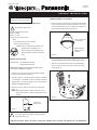
3. Attach the housing coupling to the bracket or pendant pipe
(Figure 1).
NOTE: Pipe threads should be clean and rust free. Use a
sealer (such as Tefl on™ tape or silicone sealer) on the
threads.
Figure 1
Add thread
sealing tape
Be sure the bracket is properly and securely mounted
to a supporting structure capable of rigidly holding the
weight of the entire unit.
INSTALLING QUICK RELEASE BRACKET AND PAN/TILT
CAMERA ASSEMBLY (ALL MODELS)
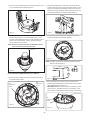
1. Open the housing by loosening the (3) captive screws located
on the housing ring next to the lower clear dome. Be careful
not to back these all the way out. Twist the dome slightly in a
counterclockwise motion to remove (Figure 2).
Figure 2
Loosen screws only,
do not remove
Remove dome by
twisting coun ter -
clock wise
2. Install the pan/tilt unit quick- release bracket. It is recom-
mended that this be done before installing the housing.
3. Spacers are provided to adjust the level of the WV-CS854
camera. Attach the spacers, two-high, to the main housing
bracket (Figure 3).
MODEL: Outdoor Dome Housing
POD8C(W), POD8CF(W), PID8C
Manufactured by:
Before attempting to connect or operate this product, please read these instructions completely.
81-IN3074
5/19/04
Figure 3
2525 Park Central Blvd. • Decatur, Ga 30035 • (770) 987-7550 • 800-554-1124 U.S. & Canada • www.videolarm.com • Fax 800-826-0366
for
NOTE: This unit is designed for operation in an
upright position. Installing the unit
upside down may cause damage to the
internal equipment, and will void the war-
ranty.

- 2 -
Safety Screw
4. Connect the quick-release bracket to the spacers using the (4) 8 x
32 x 1/2" bolts and #8 star washers (Figure 4).
Figure 4
5. Attach the unitized camera to the quick-release bracket. Secure
the safety screw (Figure 5). Connect the BNC, power, control,
and alarm cables. Make sure all wiring is clear of the blowers and
heater on the housing bracket. Use the cable tie provided to
secure the wires and connectors.
Figure 5
NOTE: Remove the plastic dome from the WV-CS854 unitized
camera to ensure the best optical picture.
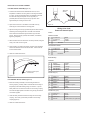
INSTALLING FIXED CAMERA BRACKET (ALL MODELS)
1. Loosen the two pan adjustment screws and rotate the bracket to
the desired viewing location.
2. Tilt and height adjustments can be made using the two screws
located on the upper portion of the fi xed camera bracket. Loosen-
ing the screws allows the bracket itself to slide up and down the
bracket arms (height adjustment) and back and forth on the cam-
era bracket (tilt). Adjust to the desired location (Figure 7).
3. The camera can also be adjusted back and forth via the slot
located on the bottom of the bracket (Figure 8).
4. Attach the camera to the bracket using the 1/4-20 hex bolt
provided. Make fi nal adjustments and lock down the pan, tilt, and
height adjustment screws (Figure 10).
IMPORTANT NOTE: Put the dome in place to assure the camera
does not touch it. To reattach the dome you must twist it, if the
dome comes in contact with the camera its position could change.
Figure 6
Figure 7
Figure 8
Figure 10
Pan
adjustment
screw
Tilt
adjustment
screw
Pan
adjustment
screw
1/4-20 hex bolt
NOTE: A 90˚ BNC connector is included in the packet to assist in
fi tting the camera (Figure 9).
Figure 9

- 3 -
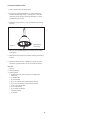
Figure 12
Twist and
Secure
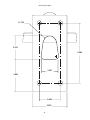
1. A wall mount bracket comes standard with this unit, and a
template is included to use as a guide for mounting the bracket
to a wall. Choose the desired location for installation and mark
the drill holes using the template. Screw (2) bolts (not
provided) about 3/4 of the way into the (2) top holes. Run
approximately 8" of wiring out of the wall.
2. Open the access door on the bottom of the wall mount by
loosening the screw nearest the mounting plate.
3. Slip the housing onto the top (2) bolts and pull the wires from the
wall through the rectangular hole in the wall mount bracket.
Screw bolts and washers through the bottom (2) holes and
secure. Remove the top (2) bolts, add washers, and reattach,
tightening completely.
4. Attach the wires from the wall to the connector provided, using the
wiring color code chart as a guide.
5. Once all wiring connections are made, place the wires inside the
wall mount bracket and close the access door. Secure with the
screw removed earlier.
6. Clean the outside of the dome.
INSTALLING THE HOUSING ASSEMBLY
FOR WALL MOUNT POD8CW (Figure 11)
FOR PENDANT MOUNT, POD8C (Figure 12)
1. Mount the housing assembly to the mounting bracket and
housing coupling. A safety cable is included with the housing to
temporarily hold it while making wiring connections. Loop the
safety cable over one of the set screws on the housing coupling
and make the appropriate connections using the (2) screw-down
connectors supplied.
2. Undo the safety cable and twist the housing onto the housing
coupling. Secure all (3) setscrews provided on the housing
coupling (Figure 4).
3. Clean the outside of the dome.
Wiring Color Code
Power and Control Inputs
1 24 VAC Live Black
2 24 VAC Live White
3 Green Green
4 Not Used
1 24 VAC Live Red
2 24 VAC Live White
3 Green Green
4 Not Used
1 Ground Brown
2 TXB (RS485) Red
3 TXA (RS485) Orange
4 RXB (RS485) Yellow
5 RXB (RS485) Green
CAMERA POWER
ACCESSORY POWER
CONTROL
Figure 11
POD8C
Pan/Tilt Unit Only
1 Alarm In 1 Black
2 Ground Brown
3 Alarm In 2 Red
4 Ground Orange
5 Alarm In 3 Yellow
6 Ground Light blue or green
7 Alarm In 4 Blue
8 Ground Purple
ALARM IN (8-pin)
1 Alarm Out 1 Gray
2 Ground White
3 Alarm Out 2 Pink
4 Ground Yellow, Green, or Light blue
ALARM OUT (4-pin)
Loosen screw to open
access door

- 4 -
FOR INDOOR PENDANT, PID8C
1. Select desired location to install housing.
2. The housing coupling is designed for a 1.0” NPT thread pipe.
Install the required length of pipe. Feed all power, control and
video wires through the pipe leaving approximately 12” of extra
wire extending from the end.
3. Install the housing top to the 1” pipe. Feed all wires into housing
(Figure 5).
4. Attach the quick release bracket for the unitized camera system
(See page 2).
5. Make electrical connections to the bracket, trim ming wire leads as
required.
6. Clean the inside of the dome. Reattach the hous ing dome and
secure the (3) captive screws. Do not over tighten the screws.
Figure 13
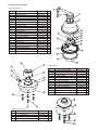
Parts List
1. Housing
2. Housing Coupling
3. Housing Packet
a. (2) Mates for screw down connectors (not supplied with
indoor units)
b. (1) Adapter plate
c. (8) 1/2" standoffs
d. (8) 8 x 32 x 3/8" Mounting screws with star washers
e. (3) 6 x 32 x 3/8" Mounting screws with star washers
f. (2) 1/4 x 20 x 3/8" HH Bolts
g. (2) 1/4” Flat washers
h. (2) 1/4" Split Lock washers
i. Instruction Manual
j. (2) Jumpers
Feed all wiring
into housing

- 5 -
28
27
26
25
24
23
22
21
20
19
18
17
33
31
32
30
29
16
15
7
13
12
11
10
9
8
7
6
5
4
3
2
1
17 1/4 x 20 FH SS Bolt 90-BTSR01 1
18 Housing Pendant Bracket 30-VL926 1
19 1/4 Split Lock Washer 92-WSSL01 1
20 1/4 Flat Washer 92-WSFL01 1
21 Housing Gasket 96-PSGK05 1
22 1/4 x 20 x 1/2" Set Screw 90-BTSS05 2
23 1/4 Flat Washer 92-WSFL01 4
24 1/4 Split Lock Washer 92-WSSL01 4
25 1/4 x 20 x .75" HH Bolts 90-BTHH27 4
26 1 1/2" Housing Coupling 30-VL1938 1
27 Upper Housing Gasket 96-PSGK04 1
28 1/4 x 20 x .375" HH Bolts 90-BTHH39 2
n/s 1/4 Flat Washer 92-WSFL01 2
n/s 1/4 Split Lock Washer 92-WSSL01 2
Item No. Description Part No. Qty
1 Wall Mount Bracket Assembly 50-WM10B 1
2 POD8 Housing Top 30-VL2156 1
3 Dome Support Ring 30-VL1695 1
4 25W, 24VAC w/Leads 72-HT1752 2
5 POD8 Clear Dome 20-DCFD8/06 1
n/s POD8 Tinted Dome 20-DTFD8/06 1
n/s 9.25" O-ring 96-RSORG11 2
6 Plastic Ring Plugs 30-VL1696 6
7 PCB 76-POD8PCB 1
8 FD8 Upper Housing Bracket 30-VL1744 1
9 Housing Gasket 96-PSGK05 3
10 Housing Fan 71-VLBL03 1
12 1/4 x 20 x .75" HH Bolts 90-BTHH27 4
12 1/4 Split Lock Washer 92-WSSL01 4
12 1/4 Flat Washer 92-WSFL01 4
13 10 x 32 x .75 Phil PH SS 90-BTRP28 3
15 Captive Screw 30-VL1749 3
n/s Captive Screw Spring 92-SPR01 3
n/s Captive Screw Retainer 94-FSRT04 3
16 Main Housing Bracket 30-VL2141 1
n/s Housing Ring 1" Lanyard Spring 92-SPR02 1
n/s Lanyard Spring Screws 90-BTPEM01 2
Pendant Assembly
Wall Mount Assembly
EXPLODED VIEWS OF HOUSING
29 PID8 Upper Housing Bracket 30-VL1013 1
30 Indoor Housing Coupling 30-VL1744 1
31 1/4 Flat Washer 92-WSFL01 1
32 1/4 Split Lock Washer 92-WSSL01 4
33 1/4 x 20 x .75" HH Bolts 90-BTHH27 4
Indoor Pendant As sem bly

- 6 -
2.000
3.250
R .733
2.132
2.981
1.537
5.500
Mounting Template

- 7 -
!
!
SAFETY PRECAUTIONSIMPORTANT SAFEGUARDS
1. Read Instructions - All the safety and operating in struc tions
should be read before the unit is operated.
2. Retain Instructions - The safety and operating in struc tions
should be retained for future reference.
3. Heed Warnings - All warnings on the unit and in the operating
instructions should be ad hered to.
4. Follow Instructions - All operating and user in struc tions should
be followed.
5. Electrical Connections - Only a qualifi ed electrician should make
electrical connections.
6. Attachments - Do not use attachments not rec om mend ed by the
product man u fac tur er as they may cause hazards.
7. Cable Runs - All cable runs must be within permissible
distance.
8. Mounting - This unit must be properly and securely mount ed to
a supporting structure capable of sustaining the weight of the
unit. Accordingly:
a. The installation should be made by a qualifi ed service person,
and should conform to all local codes.
b. Care should be exercised to select suitable hardware to
install the unit, tak ing into account both the composition of
the mount ing surface and the weight of the unit. Be sure to
periodically examine the unit and the sup port ing structure to
make sure that the integrity of the in stal la tion is intact. Failure
to comply with the foregoing could result in the unit separating
from the support structure and falling, with resultant damages
or injury to any one or anything struck by the falling unit.
UNPACKING
Unpack carefully. Electronic components can be damaged
if improperly handled or dropped. If an item appears to have
been damaged in shipment, replace it properly in its carton
and notify the shipper.
Be sure to save:
1. The shipping carton and packaging material. They are
the safest material in which to make future ship ments of
the equipment.
2. These Installation and Operating Instructions.
SERVICE
For service on Panasonic/Videolarm equipment contact:
Panasonic Technical Center
54 West Gude Dr.
Rockville MD 20850-1150
Phone: 301-762-5125
Fax: 301-251-0347
1-800-528-6747
9:00 AM - 5:00 PM EASTERN TIME
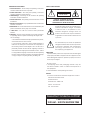
CAUTION: TO REDUCE THE RISK OF
ELECTRICAL SHOCK, DO NOT EXPOSE
COMPONENTS TO WATER OR MOISTURE.
The lightning flash with an ar row head symbol,
within an equi lat er al triangle, is intended
to alert the user to the pres ence of non-
insulated "dangerous volt age" within the
product's enclosure that may be of sufficient
mag ni tude to con sti tute a risk of electric shock
to persons.
The exclamation point within an equi lat er al
triangle is intended to alert the user to presence
of important operating and main te nance
(ser vic ing) in struc tions in the literature
ac com pa ny ing the ap pli ance.
PANASONIC TECHNICAL SUP PORT
CAUTION
RISK OF
ELECTRIC SHOCK!
-
 1
1
-
 2
2
-
 3
3
-
 4
4
-
 5
5
-
 6
6
-
 7
7


Moog Videolarm POD8CFW Product Instructions
- Category
- Camera housings
- Type
- Product Instructions
- This manual is also suitable for
Ask a question and I''ll find the answer in the document
Finding information in a document is now easier with AI
Related papers
-
Moog Videolarm 81-IN5310 RH7CS Rugged Dome Series Product Instructions
-
Moog Videolarm JK-PHO Product Instructions
-
-
-
Moog Videolarm QFDWT4-70NA Specification
-
-
Moog Videolarm DDW10CR Product Instructions
-
Videolarm QView QFDWT3-70NA User manual
-
-
Moog Videolarm DeputyDome SERIES Installation And Operation Instructions Manual
Other documents
-
Sony UNIRMB1 User manual
-
Panasonic POD9CF(W) User manual
-
Bosch Appliances Security Camera LTC 9312/00 User manual
-
-
Axis 25734 Datasheet
-
-
-
GE Security Lend Camera Installation guide
-
-
 American Dynamics SpeedDome Ultra III Installation and Service Manual
