Cannondale SCALPEL 100 User manual
- Category
- Bicycles
- Type
- User manual

READ THIS MANUAL CAREFULLY!
It contains important safety information.
Keep it for future reference.
Please note that the specications and information in this manual are subject to change for
product improvement. For the latest product information, go to http://www.cannondale.
com/tech/.
scalpel 100
Owner’s Manual Supplement
120871.PDF
SAFETY INFORMATION ............................... 1
About This Supplement .......................... 2
Important Composites Message .......... 3
Intended Use ............................................... 3
Building Up A Frameset ........................... 4
Bike Stands ................................................... 4
Extreme Temperatures ............................. 4
Inspection and Crash Damage ............. 5
Repainting and Renishing ................... 5
Tire Size ......................................................... 6
Maximum Fork Length ............................ 7
FRAME INFORMATION ................................. 8
Indentication ............................................ 8
Integrated Head Tube .............................. 3
SI BB30 Crankset .....................................10
Rear Shock ..................................................12
Recommended Sag ................................12
Shock Link Tightening Torques ...........13
Shock Link Parts .......................................14
Cable Routing ...........................................15
Frame Guards ............................................16
Right Chainstay Protector .....................17
Right Chainstay Plate .............................17
Downtube Protection ............................17
Front Der. Cable Guide ...........................18
Guide and Cable Stops ..........................18
Rear Derailluer Hanger ..........................19
MAINTENANCE ..............................................20
Schedule .....................................................20
Cleaning ......................................................21
Tightening Torques .................................21
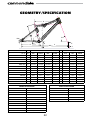
GEOMETRY/ SPECIFICATION ...................22
Geometry....................................................22
Frame Specs...............................................22
Rear Shock Specs .....................................22
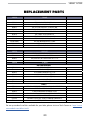
REPLACEMENT PARTS .................................23
OWNER NOTES ..............................................24
CONTENTS

2
SAFETY
INFORMATION
About This Supplement
Cannondale Owner’s Manual Supplements
provide important model specic safety,
maintenance, and technical information. They
are not replacements for your Cannondale
Bicycle Owner’s Manual.
This supplement may be one of several for
your bike. Be sure to obtain and read all of
them.
If you need a manual or supplement, or have a
question about your bike, please contact your
Cannondale Dealer immediately, or call us at
one of the telephone numbers listed on the
back cover of this manual.
You can download Adobe Acrobat PDF
versions of any Cannondale Owner’s Manuals
or Supplements from our website: http://www.
cannondale.com/bikes/tech.
• This manual is not a comprehensive
safety or service manual for your bike.
• This manual does not include assembly
instructions for your bike.
• All Cannondale bikes must be completely
assembled and inspected for proper
operation by a Cannondale Dealer before
delivery to the owner.
WARNING
This supplement may include procedures
beyond the scope of general mechanical
aptitude.
Special tools, skills, and knowledge may
be required. Improper mechanical work
increases the risk of an accident. Any
bicycle accident has risk of serious injury,
paralysis or death. To minimize risk
we strongly recommend that owners
always have mechanical work done by an
authorized Cannondale retailer.
Important Composites
Message
Your bike is made from composite materials
also known as “carbon ber.”.
All riders must understand a fundamental
reality of composites. Composite materials
constructed of carbon bers are strong and
light, but when crashed or overloaded, carbon
bers do not bend, they break.
For your safety, as you own and use the bike,
you must follow proper service, maintenance,
and inspection of all the composites (frame,
stem, fork, handlebar, seat post, etc.) Ask your
Cannondale Dealer for help.
We urge you to read PART II, Section D. “Inspect
For Safety” in your Cannondale Bicycle Owner’s
Manual BEFORE you ride.
WARNING
YOU CAN BE SEVERELY INJURED,
PARALYZED OR KILLED IN AN ACCIDENT
IF YOU IGNORE THIS MESSAGE.

120871.PDF
3
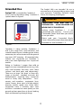
Intended Use
Scalpel 100 is intended for Condition 3
(Cross-Country, Marathon) riding. Condition 3
symbol shown in Figure 2.
For riding on
unimproved
trails with
small obstacles
Figure 2.
Condition 3 riding includes Conditions 1
and 2, plus rough trails, small obstacles, and
smooth technical areas, including areas where
momentary loss of tire contact with the ground
may occur. NOT jumping. All mountain bikes
without rear suspension are Condition 3,
and so are some lightweight rear suspension
models.
Riding in Condition 3 ranges from mild to
aggressive over intermediate terrain (e.g., hilly
with small obstacles like roots, rocks, loose
surfaces and hard pack and depressions).
There are no large “sick drop” or drop os,
jumps or launches (wooden structures, dirt
embankments) requiring long suspension
travel or heavy duty components. Cross-
country and marathon equipment (tires,
shocks, frames, drive trains) are light-weight,
favoring nimble speed over brute force.
Suspension travel is relatively short since
the bike is intended to move quickly on the
ground and not spend time in the air landing
hard, and hammering through things.
The Scalpel 100 is not intended for use in
extreme forms of jumping/riding such as hard
core mountain, Freeriding, Downhill, North
Shore, Dirt Jumping, Hucking etc.
WARNING
UNDERSTAND YOUR BIKE AND ITS
INTENDED USE. USING YOUR BIKE THE
WRONG WAY IS DANGEROUS.
Industry usage Conditions 1 - 5 are
generalized and evolving. Consult your
Cannondale Dealer about how you intend
to use your bike.
Please read your Cannondale Bicycle
Owner’s Manual for more information about
Intended Use and Conditions 1-5.

4
Building Up A Frameset
Before building up a frameset, consult with
your Cannondale Dealer and the component
manufacturers, and discuss your riding style,
ability, weight, and interest in and patience for
maintenance.
Make sure the components chosen are
compatible with your bike and intended for
your weight and riding style.
Generally speaking, lighter weight components
have shorter lives. In selecting lightweight
components, you are making a trade-o,
favoring the higher performance that comes
with less weight over longevity. If you choose
more lightweight components, you must
inspect them more frequently. If you are a
heavier rider or have a rough, abusive or “go for
it” riding style, buy heavy duty components.
Read and follow the component manufacturers
warnings and instructions.
Bike Stands
The clamping jaws of an ordinary bike stand
can generate a crushing force strong enough
to seriously damage and ruin your bike frame.
CAUTION
Never place your bike in a bike stand by
clamping the frame. Place your bike in a stand
by extending the seat post and positioning
the stand clamp on the extended seat post.
Don’t extend beyond the MINIMUM INSERT
line marked on the seat post.
Since your carbon seat post can also be
damaged by clamping force, adjust the
stand clamp for the minimum clamping force
needed to secure the bike.
Its a good idea to remove your current seat
post and use an old one when mounting
your bike in a stand.
Protect From
Extreme Temperatures
• Protect your carbon bike from extreme
temperatures when storing or transporting it.
• Allow your bike to cool o or warm up before
you ride
• Do not store your bike in places where the
temperature will exceed 66.5C° (150°F). For
example, do not leave your bike lying at in
a black pickup truck bed in the desert sun, or,
under the glass of a hatchback auto.

120871.PDF
5
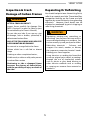
Inspection & Crash
Damage of Carbon Frames
WARNING
AFTER A CRASH OR IMPACT:
Inspect frame carefully for damage (See
PART II, Section D. Inspect For Safety in your
Cannondale Bicycle Owner’s Manual.)
Do not ride your bike if you see any sign
of damage, such as broken, splintered, or
delaminated carbon ber.
ANY OF THE FOLLOWING MAY INDICATE
A DELAMINATION OR DAMAGE:
An unusual or strange feel to the frame
Carbon which has a soft feel or altered
shape
Creaking or other unexplained noises,
Visible cracks, a white or milky color present
in carbon ber section
Continuing to ride a damaged frame
increases the chances of frame failure,
with the possibility of injury or death of
the rider.
Repainting Or Renishing
You should not paint over the existing finish,
refinish or repaint your bike. The carbon fiber
composites making up the frame are held
together by some extremely strong bonding
chemicals. However, these bonds can be
attacked or weakened by paint stripping or
refinishing chemicals.
WARNING
Repainting, painting over, retouching, or
renishing your frame or fork can result in
severe damage leading to an accident. You
can be severely injured, paralyzed or killed.
Renishing chemicals : Solvents, and
strippers can attack, weaken, or destroy
the important composite chemical bonds
holding your frame together.
Using abrasives or sanding the frame/fork
structure, original paint, decals, or coatings
through the use of mechanical actions
such as plastic or glass bead blasting or
other abrasive methods such as sanding
or scraping can remove frame material or
weaken it.

6
Tire Size
WARNING
OBSERVE THE “MAXIMUM TIRE WIDTH” FOR YOUR BIKE FOUND IN THE SPECIFICATIONS
PAGE OF THIS MANUAL.
Mounting the wrong size tires can result in the tires hitting the fork or frame when riding. If
this happens, you can lose control of your bike and you can be thrown o, a moving tire can
be stopped because it touches the fork or frame.
Do not mount oversized tires, ones that rub or hit the fork or frame, ones that result in too
little clearance, or ones that can hit the fork or frame when the suspension is fully compressed
or when riding.
Take care that the tires you select are compatible with your bike’s fork or frame design. Also,
be sure to follow the manufacturer’s recommendations of your front fork and rear shocks.
When you are considering tires for your bike consider...
The actual measured size of a tire may be dierent than its sidewall marking. Each time you
mount a new tire, take the time to inspect the actual clearance between the rotating tire
and all parts of the frame. The U.S. Consumer Product Safety Commission (CPSC) requires at
least 1/16” (1.6 mm) tire clearance from any part of the bike. Allowing for lateral rim ex and a
wheel or rim that is out-of-true will likely mean choosing a rear tire that provides even more
clearance than the CPSC recommends.
ASK YOUR CANNONDALE DEALER FOR THE RIGHT TIRES FOR YOUR BIKE AND ITS
PARTICULAR COMPONENTS!
YOU CAN BE SEVERELY INJURED, PARALYZED OR KILLED IN AN ACCIDENT
IF YOU IGNORE THIS WARNING.

120871.PDF
7
HEADTUBE
HEADSET
PARTS or
ADAPTERS
AX
L
E
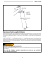
MAXIMUM FORK LENGTH
500 mm
Maximum Fork Length (500mm)
Maximum Fork Length is an important frame safety testing specication. You must observe the
measurement when installing headset parts, headset adapters, installing and adjusting a fork,
and selecting replacement forks. In this manual, the number is also listed in the specications
section.
HOW TO MEASURE: 1. Install headset and fork. 2. Extend fork and measure the distance from
the bottom of the head tube to the center of the wheel axle. Do not measure from the bottom of
headset bearing cups or head tube adapters. The measurement MUST be taken from the bottom
of the head tube!!
WARNING
DO NOT EXCEED MAXIMUM FORK LENGTH
Exceeding the MAXIMUM FORK LENGTH limit can overload the frame causing it to fail (break)
while riding.
YOU CAN BE SEVERELY INJURED, PARALYZED OR KILLED IN AN ACCIDENT
IF YOU IGNORE THIS WARNING.

8
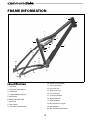
FRAME INFORMATION
1.
12.
15.
14.
13.
16.
17.
18.
20.
19.
6.
7.
8.
2.
9.
10.
11.
5.
4.
3.
Identication
1. Top Tube
2. Top Tube Shock Mount
3. Head Tube
4. Integrated Bearing Cup
5. Downtube
6. Bottom Bracket Shell
7. Seat Tube
8. Rear Shock
9. Seat tube Shock Mount
10. Shock Link Assembly
11. Seat Stay Bridge
12. Left Seat Stay
13. Right Seat Stay
14. Left Chainstay
15. Chainstay Bridge
16. Right Chainstay
17. Right Dropout
18. Rear Derailleur Hanger
19. Left Dropout
20. Rear Disc Brake Mounting

120871.PDF
9
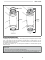
HEADSHOK
1⅛ “
KP058/
HD169/
QSISEAL/
(adapters w/
headset)
Integrated Head Tube
In both alloy and carbon frame models, the SI bearing cups are intergrated within the head
tube. In alloy frames, the cups are machined in the head tube. In carbon models, cups are
permanently bonded into the head tube. Cannondale Headshok System Integration bearings
are accepted directly into both type.
An adapter cup kit (KP058/) for 1
⅛” steering tubes and headsets is available (above right) for
either frame type.
CAUTION
1. Do not face, surface, or cut the head tube bearing cups.
2. Please note that when removing bearings from bonded cups, extra care must be used so
that the tool used to drive out the bearing is NOT located on any part of the bonded cup.

10
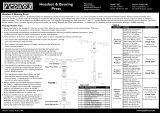
SI BB30 Crankset Compatability
The BB shell is compatable with the BB30 Standard. See http://www.bb30standard.com/ For
information see SI Cranksets Owner’s Manual Supplement. See http://www.cannondale.com/
tech/.
Bearing Maintenance
Shell bearings (KB6180/) are sealed cartridge type and do not require lubrication. Inspect
bearing condition annually (at a minimum) and anytime the crankset assembly is disassembled
or serviced. The bearings are a press t within the shell. Old bearings should not be reinstalled
if removed. Replace both bearings at the same time.
Replacements circlips (QC616/) are available if the circlips become damaged. The circlips can be
lifted from the BB groove (inset) by lifting the hooked end with a thin blade screwdriver.
CAUTION
DO NOT FACE, MILL OR MACHINE THE BOTTOM BRACKET SHELL FOR ANY REASON.
Doing so can result in serious damage and possibly a ruined bike frame.
Cannondale SI BB30 Tools
KT011/ is a bearing removal tool. KT010/ is a set of bearing installation tools to be used with
a standard headset press. KT013/ a two piece tool set required for removing SI Hollowgram
alloy cranksets. For information see SI Cranksets Owner’s Manual Supplement. See http://www.
cannondale.com/tech/.
SI BB30-to-68mm Standard Adapter
The adapter (Cannondale kit KF365/) converts the BB30 bottom bracket cranksets for use with
68mm bottom brackets.
The adapter IS NOT a repair part and will only work in undamaged frames in good condition.
Improper installation or removal can result in damage and void applicable frame warranty.

120871.PDF
11
KB6180/
KT011/
KT010/
Lo
c
tite 609 (g
r
een)
KF365/
groove
DRIVE SIDE
QC616/
KT013/
8mm

12
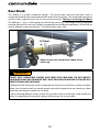
Rear Shock
The Scalpel is a unique suspension design. The living hinge seat and chainstays work in
conjunction with the rear shock and provide some of the spring rate. This integrated spring force
results in riders requiring much less air pressure than normal. The key is to set sag @ 8-10mm.
The eect of +/- 5 psi is much greater at these lower pressures. Percentage wise the dierence
between 50 and 55 on the new Scalpel is comparable to the dierence between 150 and 160 on
more traditional suspension designs. So, little changes mean a lot.
8-10mm
WARNING
SELECT ONLY COMPATIBLE SHOCKS AND FORKS FOR YOUR BIKE. DO NOT MODIFY
YOUR BIKE IN ANY WAY TO MOUNT ONE. HAVE YOUR SHOCK OR FORK INSTALLED BY A
PROFESSIONAL BIKE MECHANIC
• Riding with the wrong rear shock can damage the frame. You could have a serious accident.
Make sure the total travel, eye-to-eye length, and stroke length of the rear shock you select
meet the specications listed in this manual.
• When selecting dierent shocks or forks for your bike, make sure that the shock or fork you
select is compatible with your bike’s design and how you will use your bike.
Adjust air pressure to achieve 8-10mm of rear
shock sag.

120871.PDF
13
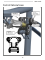
Shock Link Tightening Torques
5mm Allen
13 Nm, 115 In Lbs
4mm Allen
7 Nm, 62 In Lbs
Loctite 242 (blue)
4mm Allen
7 Nm, 62 In Lbs
Loctite 242 (blue)
5mm Allen
13 Nm, 115 In Lbs
4mm Allen
7 Nm, 62 In Lbs
Loctite 242 (blue)

14
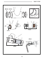
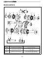
Shock Link Parts
121559
121549
A
E
117165
H
117165
H
135S
I
121559
E
116963
L
121563
K
121559
E
121648
B
121648
B
121564
J
121562
D
121560
C
121648
B
117165
H
121647
G
121559
E
121561
F
121561
F
135S
I
121648
B
121560
C
121562
D
FRONT SHOCK MOUNTING HARDWARE
ORDER KIT ITEM (QTY)
KP050/ SHOCK MOUNTING HARDWARE G (1), L (1), I (2), H (3)
KP051/ SHOCK LINK ASSY W/0 LINK
E (4), C (2), F (2), D (2), K (1), L (1), G (1), J (3),
I (2), B (4)
KP052/ COMPLETE SHOCK LINK ASSY
A (1), E (4), C (2), F (2), D (2), K (1),
J (1), L (1), G (1), H (3), I (2), B (4)

120871.PDF
15
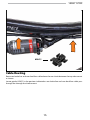
KP057/
Cable Routing
Route rear brake line and rear derailluer cable above the rear shock between the top tube mount
as shown.
Locate guides KP057/ in the postions indicated as rear brake line and rear derailluer cable pass
through the through the shock mount.

16
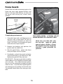
Frame Guards
Normal line and cable movement against the
frame can wear away painted nishes and
decals. Overtime, cable rubbing can wear into
the frame itself causing very serious frame
damage.
KF103/
(8 pcs)
To apply the guard material :
1. Clean the frame with a mild detergent and
wipe dry with a clean towel. Do not use
solvents or harsh chemicals to clean the
frame. OPTIONAL: Trim the adhesive guard
material to the shape required.
2. Remove the backing and position the
guard under the cable/ line.
3. Rub the guard rmly against the frame
with your ngers to x it in place.
4. Periodically, recheck the guards and other
areas of the frame as you continue to ride.
Replace the guards if they wear out.
PLEASE NOTE: Damage to your bike caused by
cable rubbing is not a condition covered under
your warranty. Also, adhesive frame guards
are not a x for incorrectly installed or routed
cables or lines. If you nd that applied guards
are wearing out very quickly, consult with your
Cannondale Dealer about the routing on your
bike.
THIS PHOTO SHOWS A TYPICAL USE OF
GUARD MATERIAL AT A CONTACT POINT.
Check over your bike after your
rst few rides. Apply the guard
material where rubbing is found.
When applied correctly, the guards
material is good protection for
your bike.

120871.PDF
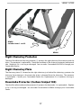
17
2.
1.
3.
KP054/
KP053/
includes items 1. and 2.
Right Chainstay Protector
The clear lm adhesive chainstay protector (1) protects the right chainstay from contact with the
chain. The protector is replaceable. Check the condition of the chainstay protector before each
ride. Replace it if it is missing or damaged. You can order Cannondale kit KP053/ through your
Cannondale Dealer.
Right Chainstay Plate
The chainstay plate (2) located on the right chainstay just behind the chainrings, protects the
chainstay from damage in the event the chain is dropped from the chainring. The protector
is replaceable. Contact your Cannondale Dealer for a replacement if it is becomes missing or
damaged.
Downtube Protector (Carbon Scalpel 100)
The clear lm adhesive downtube protector (3) protects the downtube. It is replaceable. Replace
it if it is missing or damaged. You can order Cannondale kit KP054/ through your Cannondale
Dealer.

18
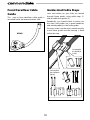
Front Derailleur Cable
Guide
This snap in front derailleur cable guide is
mounted under the bottom bracket shell.
KF085/
Guides And Cable Stops
Lines and cables on your bike are routed
through frame guides using cable stops (1)
and /or cable thru guides (2).
Periodically, you should check to make sure
the stops and guides are in good condition
and seated properly in the frame guides.
For stops, make sure the stop is seated securely
in the frame guide and the housing is xed
within the stop.
(a)
1
2
Cannondale
Kit # KF014/
(2 PK)
Cannondale
Kit # KF086/
(10 PK)

120871.PDF
19
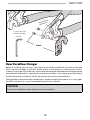
1.1 N•m, 10 In•Lbs
Loctite 242 (blue)
KH048/
2.5 mm
Appy a lm of
grease her
e
Rear Derailleur Hanger
Before re- installing (same or new): Clean dropout and inspect carefully for any cracks or damage.
Clean surfaces and apply a light lm of bike grease to the dropout to minimize any noise or
“creaking” that might result from very slight movement between the dropout and hanger during
movement of the derailleur. Apply grease and Loctite carefully. Do not contaminate the male or
female bolt threads with grease which would cause the Loctite to be ineective.
Check derailleur adjustment after replacement. Readjust wheel quick release so it is very tight.
See PART I Section 4. A in your Cannondale Bicycle Owner’s Manual.
CAUTION
Do not use a derailleur hanger alignment tool to straighten.

20
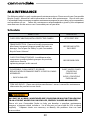
maintenance
The following table lists only supplemental maintenance items. Please consult your Cannondale
Bicycle Owner’s Manual for more information on basic bike maintenance. Consult with your
Cannondale Dealer to create a complete maintenance program for your riding style, components,
and conditions of use. Follow the maintenance recommendations given by the component
manufacturers for the various non-Cannondale parts of your bike.
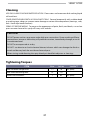
Schedule
WHAT TO DO HOW OFTEN
CHECK FOR CABLE RUB, INSTALL PROTECTIVE GUARDS AFTER FIRST RIDE
FRAME INSPECTION - Clean and visually inspect entire
bike frame/swingarm/linkage assembly for cracks or
damage. See “Inspect For Safety” in your Cannondale
Bicycle Owner’s Manual.
BEFORE AND AFTER
EACH RIDE
CHECK TIGHTENING TORQUES - In addition to other
component specic tightening torques for your bike,
check items listed in
tightening torques in this manual.
BEFORE EVERY RIDE
DISASSEMBLE, CLEAN, INSPECT, RE-GREASE,
REPLACE WORN OR DAMAGED PARTS IN THE FOLLOWING
ASSEMBLIES:
• SHOCK LINK ASSY
IN WET, MUDDY, SANDY
CONDITIONS
EVERY 25 HRS.
IN DRY, CONDITIONS
EVERY 50 HRS.
FORK AND SHOCK - Please consult the manufacturer’s owner’s manual for maintenance
information for your fork or rear shock.
WARNING
ANY PART OF A POORLY MAINTAINED BIKE CAN BREAK OR MALFUNCTION LEADING
TO AN ACCIDENT WHERE YOU CAN BE KILLED, SEVERELY INJURED OR PARALYZED.
Please ask your Cannondale Dealer to help you develop a complete maintenance
program, a program which includes a list of the parts on your bike for YOU to check
regularly. Frequent checks are necessary to identify the problems that can lead
to an accident.
Page is loading ...
Page is loading ...
Page is loading ...
Page is loading ...
-
 1
1
-
 2
2
-
 3
3
-
 4
4
-
 5
5
-
 6
6
-
 7
7
-
 8
8
-
 9
9
-
 10
10
-
 11
11
-
 12
12
-
 13
13
-
 14
14
-
 15
15
-
 16
16
-
 17
17
-
 18
18
-
 19
19
-
 20
20
-
 21
21
-
 22
22
-
 23
23
-
 24
24


Cannondale SCALPEL 100 User manual
- Category
- Bicycles
- Type
- User manual
Ask a question and I''ll find the answer in the document
Finding information in a document is now easier with AI
Related papers
-
Cannondale Scalpel 80 Owner's manual
-
-
-
-
-
-
-
-
-
Other documents
-
Kettler 8947-933 Owner's manual
-
sks ROWDY SET User manual
-
Bontrager 253427 User manual
-
-
-
-
-
 Yeti SB120 Bike Frame Protection Kit User manual
-
 K-EDGE K13-240 Installation guide
-
 PEDRO S 6450920 User guide


