
OPERATOR'S
MANUAL
for
tIIIEStERBEICE
1()
TWO
)\
MARINE ENGINE
AND
tIIIES.,.ERBEICE
SlCtIII
GENERATOR SET
Publication
Number
33105
Printed in
U.S.A.
J. H.
WESTERBEKE
CORP.
AVON
INDUSTRIAL
PARK,
AVON,
MASS.
02322·
{6f7}
588
7700
CABLE:
WESTCORP,
AVON·
TELEX:
92
4444

~------
C.ALI
IA

FOREWORD
Thank
you
for
having
selected
a
Westerbeke
Diesel
Engine
for
your
use.
This
manual
describes
the
procedures
for
proper
handling
and
maintenance
of
both:
(a)
10
Horsepower
Marine
Propulsion
Engine
(b)
3
KW
Marine
Generator
Set
To
obtain
best
operating
condition
and
longest
life,
it
is
important
to
use
it
sensibly
and
carry
out
operatiorl
and
maintenance
according
to
this
manual
•.
If
you
have
questions
about
your
equipment
or
in
the
event
of
a
failure,
please
contact
your
nearest
distributor
or
dealer.
We
look
forward
to
your
continued
patronage.
1

TABLE
OF
CONTENTS
PAGE
GENERAL
SPECIFICATIONS
••••••••••.••••
3
CAUTIONS
IN
HANDLING ENGINE
••••••••••
4
1
• B
REA
KIN
GIN
• • • • • • •
..
•
..
• • • 0
..
• • • •
••
5
2.
PREPARATIONS
.....................
6
3.
STARTING PROCEDURES
•.••...•.••••
7
4.
STOPPING PROCEDURES
.••••.••.••••
I0
5.
CAUTIONS
ON
STARTING
AND
OPERATION
•••
".
0
••
co
.........
0
..
10
6.
REQUIREMENTS FOR PROPER
OPERATION
6-1
Lubrication
System
•.•..•••.
12
6-2
Fuel
System
•.•••••••.••••••
13
6-3
Cool
System
..•••.•••••••
16
6-4
Wiring
iagram~~
•••••.••..•
18
6 - 5
Bel
t 'r
ens
ion.
..
• " e _ •
..
• • •
..
• •
..
18
6-6
Domestic
Hot
Water
.••••.•.•
18
7
RECOMfRIENDED
MAINTENANCE SERVICE
.19
8.. TRANSMISSIONS..
..
• •
..
.
...
...,
..............
22
9.
TROUBLESHOOTING
.....
~
0
•••••••
23
10
..
SERVICE
DATA
..................
"
..
_
......
24
11
..
TABLE
OF
TIGHTENING TORQUES"
..•
24
12.
INSTRUCTIONS:
3KW
GENERATOR
SET.25
14.
STOPPING
PROCEDUP~.e~o
••••••••••
28
15..
WIRING
DIAGRAM
............
"
...................
29
17
..
EXPLODED VIEW
GENERA
f
I
1
0R
PORTION
..
30
18
..
GENERAL
INFORMATION ELECTRICAL
••
31
19..
MAl
NlfENANCE
..
"
............
" ........
II
........
,,32
20.
INTERNAL WIRING
DIAGRAM
..........
33
21.
LIMITED
WARRANTY
•••••••••.•.•.••
34
2

GENERAL
SPECIFICATIONS
ENGINE
Type
Vertical
4
cycle,
water
cooled
No.
of
cylinders
Two
Bore
&
stroke
(inches)
2.56
X
2.68
Cubic
inch
displacement
27.52
Compression
ratio
25:1
Firing
order
1-2
Dry
weight,
engine
only
128
pounds
Injection
pump
Bosch
type
Injectors
Throttle
type
Combustion
chamber
Swirl
type
Fuel
#2
diesel
Governor
Centrifugal
weight
type
Lubrication
system
Pressure
by
trochoid
pump
Oil
filter
Paper
type,
engine
mounted
Engine
oil
capacity
2
quarts
Cooling
system
Forced
circulation
through
heat
exchanger
Electric
starter
12
volt,
1
horsepower
Alternator
35
ampere,
12
volt
Glow
plugs
Sheathed
quick
heat
type
Battery
capacity
Recommend
60
amp
hour
Generator
type
Insulation
GENERATOR
4
pole,
revolving
regulated,
self
excited,
AC
slip
design
Class
F
3
armature,
inherently
limiting,
rectifier
rings,
single
bearing

INSTALLATION
AND
SUPPLY CAUTIONS
*
Check
important
aspects
of
installation
before
operating
engine
.
(1)
Alignment
(Error
to
be
no
more
than
one
thousandth
of
an
inch
per
inch
of
coupling
diameter)
(2)
Provide
sufficient
ventilation
(3)
Provide
around
clauses)
adequate
service
room
engine
(See
warranty
.
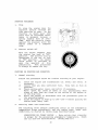
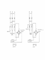
003
FEELER
GAGE
CHECKING
COUPLING
ALIGNMENT
*
Fill
fuel
tank
with
CLEAN
#2
diesel
from
a
reputable
manufacturer.
*
Fill
lubricating
oil
to
full
mark
on
dipstick
(Select
readily
available
lubricating
oil
of
grade
CC
or
CD).
*
Fill
water
with
suitable
mixture
of
water
and
antifreeze
to
suit
your
temperature
zone.
See
page
16.
*
Plug-in
Panel
Harness
Connection.
After
assembly,
joint
should
be
taped
to
prevent
corrosion
or,
preferably,
assembled
using
a
sili-
con
grease
which
can
be
obtained
at
an
electronic
store
such
as
Radio
Shack.
SAFETY PRECAUTIONS
*
*
*
*
Never
operate
engine
with
inadequate
ventilation.
Do
not
touch
moving
parts
during
operation.
Do
not
touch
hot
parts
such
as
exhaust
pipe,
and
do
not
place
com-
bustible
materials
near.
Inspect
and
adjust
parts
of
the
engine
only
after
it
is
stopped.
*
Check
and
refill
engine
oil,
cooling
water
and
fuel
after
the
engine
is
brought
to
a
stop.
*
In
checking
the
water
level
for
refilling,
remove
the
pressure
cap
only
after
the
water
temperature
has
fallen
enough
to
prevent
a
steam
burn.
*
Always
use
tools
that
fit
cor
rectly
and
use
caution
dur
ing
ser-
vicing.
* Be
sure
that
current
carrying
wires
are
protected
from
abrasion
and
that
all
connections
are
tight.
4

BREAKING IN
YOUR
NEW
ENGINE
While
your
engine
has
had
individual
test
operations
sufficient
to
demonstrate
accurate
assembly
and
correct
operation
of
all
systems,
it
still
requires
break
in
time~
Service
life
of
your
engine
is
dependent
on
how
your
engine
is
operated
and
serviced
during
the
initial
twenty
hours
of
operation.
Your
new
engine
needs
twenty
hours
of
conditioning
operation
for
breaking
in
each
moving
part,
thus
maximizing
performance
and
life
of
eng
Ine.
Perform
this
condi
tioning
carefully,
keeping
the
following
points
in
mind.
1.
Start
engine,
run
idle
while
checking
that
all
systems
are
functioning
-
sea
water
pump,
oil
pressure,
battery
charge.
2.
Warm
eng
ine,
preferably
by
running
propeller
at
fast
idle
while
tied
down,
until
water
temperature
gauge
moves
into
the
130
-
140
degree
range.
3.
Then
use
engine
at
moderate
load
(60%
±)
for
first
five
hours.
4.
Avoid
rapid
acceleration.
5.
Use
caution
not
to
overload
engine.
Grey
or
black
smoke
is
a
sign
of
overload.
6.
Next
fifteen
hours
may
be
run
at
70
-
75%
load.
Explanation:
"Breaking
in"
a new
en~ine
is
basically
a
seating
of
the
piston
rings
to
the
cylinder
walls.
This
is
not
accomplished
by
long
per
iods
of
runnIng
idle,
nor
by
early
running
under
full
load,
nor
by
varying
loads
with
intervals
of
fast
acceleration
and/or
excessive
speed.
Idle
running
may
glaze
the
cylinder
walls
causing
oil
consumption
and
smoky
operation.
Excessive
speeds
and
loads
may
score
cylinder
walls
with
similar
results.
As
indicated
above,
use
a
short
warm
up
at
idle
and
put
engine
under
moderate
load
and
speed
for
the
first
five
hours
of
operationo
For
the
next
fifteen
hours,
use
approximately
70%
load.
'rhis
kind
of
careful
operation
will
result
in
best
results
from
your
engine&
5

PREPARATIONS
Take
steps
as
shown
below
in
starting
your
engine
for
the
first
time
or
after
a
prolonged
shut-down.
1.
Fill
your
engine
with
oil
up
to
or
near
the
upper
limit
on
the
dipstick.
Use
a
good
grade
of
oil
with
API
specification
of
CC
or
better.
For
quantity
of
oil,
you
may
refer
to
the
General
Specifications
page.
However,
it
is
best
always
to
be
guided
by
dipstick
measure-
ment
as
angle
of
installation
has
some
effect.
2.
Your
engine
is
supplied
with
a
coolant
recovery
system
to
which
the
following
instruc-
tions
apply:
a)
Fill
engine
completely
to
the
neck
of
the
manifold
cap.
b)
Then
fill
the
recovery
tank
to
the
bottom
level
line.
Need
for
adding
coolant
is
indicated
when
a
cold
engine
has
coolant
level
below
the
bottom
level
line.
c)
In
winter
add
antifreeze
as
described
on
page
16.
Anti-
freeze
may
be
used
year
round
if
changed
annually.
3.
Fill
the
fuel
tank
with
Diesel
fuel.
The
interior
of
the
fuel
tank
must
be
maintained
clean.
Be
careful
not
to
allow
intro-
duction
of
dirt
when
filling
fuel
..
4 •
Engine
oil,
coolant
transmission
levels
should
checked
at
least
once
a
prior
to
engine
use.
and
be
day
6
011
filler
port

STARTING
PROCEDURES
Instrument
panel,
description
and
use
of:
......
"'"
Note
1:
When
engine
is
stopped
after
use,
the
water
temperature
and
oil
pressure
gauges
may
stay
at
their
running
readings.
Note
2:
When
eng
ine
is
next
to
be
used,
turn
start
swi
tch
to
"ON".
The
temperature
and
pressure
gauges
will
"ZERO"
and
the
volt-
meter
will
register
battery
voltage.
The
electric
fuel
pump,
mounted
on
the
engine,
will
also
begin
to
operate,
purging
any
air
accumulated
in
the
system.
Note
3:
The
engine
is
now
prepared
for
starting.
7

STARTING
PROCEDURES
1.
Turn
the
starter
switch
to
the
liON"
posi
tiona
If
making
an
ini
tial
start
after
lay-up,
fuel
filter
servicing
or
repairs,
allow
fuel
pump
to
work
lS-2S
seconds
to
purge
the
system
of
any
air.
Check
that
clutch
is
in
neutral
and
that
throttle
is
in
full
forward.
2.
Glow
plug
preheating
with
key
in
1I0N
II
position,
push
in
about
1/4
inch
or
enough
so
that
voltmeter
indicates
dis-
charge.
Hold
key
in
depressed
posi
tion
until
glow
plugs
are
sufficiently
hot.
Follow
Table
below
for
preheating
time.
Quick-heat
type
(Yl14T)
Atmospheric
temperature
+S-C
(+41-F)
or
higher
+S-C
(+41-F)
to
-S-C
(+23-F)
-S·C
(+23-F)
or
lower
Limit
of
continuous
use
3_
Proper
glow
plug
function
is
indicated
by
vol
tmeter
drop
when
key
is
depressed
_
This
drop
will
be
slight
but
dis-
cernible_
If
no
voltage
drop
is
noted,
it
may
indicate
defecti
ve
glow
plugs
or
a
faulty
preheat
circuit
(check
for
loose
connection).
8
Preheating
Approx.
10
Approx.
20
Approx.
30
1
minute
time
sec.
sec.
sec
..

4.
Starting
Continuing
to
hold
the
key
depressed,
turn
to
the
"START"
position.
The
starter
motor
will
run
thereby
cranking
the
engine.
Hold
throttle
open
until
engine
runs
and
then
reduce
throttle.
Should
the
engine
not
start
even
when
the
starter
switch
is
left
at
"s"
position
for
10
seconds,
take
your
hand
off
the
starter
switch
for
30
seconds,
and
then
attempt
to
start
the
engine
again
by
sufficiently
preheating
the
glow
plug.
The
starter
motor
should
never
be
allowed
to
run
for
more
than
30
seconds
at
a
time.
5.
Operation
As
soon
as
the
engine
has
star
ted,
release
the
key.
The
key
will
automatically
return
to
the
"ON"
posi
tiona
Leave
the
key
at
"ON"
dur
ing
oper
a-
tion.
Check
that
wi
th
eng
ine
running,
oil
pressure
and
bat-
tery
charge
voltage
are
registering
and
that
raw
water
is
discharging
with
the
exhaust.
During
engine
operation,
do
not
turn
the
key
to
"s"
position.
may
damage
the
starter
motor.
6.
Warm-up
operation
Run
a
few
minutes
at
"IDLE"
position
to
assure
that
all
functions
are
operating.
Then
operate
under
reduced
load
until
water
temperature
rises
into
the
140-150·
range.
9
This

STOPPING
PROCEDURE
1.
Stop
To
stop
the
engine
move
the
throttle
control
through
the
idle
position
to
stop.
As
the
throttle
is
moved
past
idle
there
will
be
increased
resis-
tance
to
movement
because
a
spring
loading
must
be
over-
come.
Hold
the
throttle
firmly
against
the
pressure
until
the
engine
comes
to
a
complete
stop.
2.
Starter
switch
off
Wi
th
the
eng
ine
stopped,
turn
the
starter
key
back
to
"OFF"
position.
The
battery
will
be
discharged
if
the
key
is
left
at
"ON"
position.
An
engine
alarm
buzzer
is
provided
to
warn
the
operator
of
this
possibility.
Best
precaution
is
always
to
remove
the
key.
CAUTIONS
ON
STARTING
AND
OPERATION
1.
Normal
starting
Follow
the
procedures
below
for
routine
starting
of
your
engine.
I}
Check
the
engine
and
transmission
oil
levels
and
refill
if
necessary.
2}
Insure
that
you
have
sufficient
fuel.
Keep
tank
as
full
as
possible.
3}
Check
cooling
water
level,
and
refill
if
necessary~
Note:
Check
for
leaks
of
water
or
oil,
particularly
\-lhen
signs
of
such
leak
are
found
on
the
bottom
of
the
e~gine
or
in
the
drip
tray.
4)
Start
the
engine
in
accordance
with
the
procedures
given
on
the
preceding
pages.
5}
Allow
the
engine
to
warm
up
to
140·-150·
F
before
placing
the
engine
under
heavy
load.
2.
Starting
under
cold
conditions
The
following
three
adverse
conditions
concur
as
the
atmospheric
temperature
drops
exceedingly,
and
the
engine
must,
under
such
conditions,
be
started
by
taking
steps
described
below:
LUBRICATING
OIL
TURNS
VISCOUS Make
certain
that
viscosity
is
proper
for
the
prevailing
atmospheric
temperature.
Check
the
oil
also
for
deterioration.
(Study
page
12.)
10

VOLTAGE
ACROSS
BATTERY
TERMINALS
DROPS
battery
is
fully
charged.
Check
that
the
THE
TEMPERATURE
OF
INTAKE
AIR
IS
LOW
AND
COMPRESSION
TEMPERATURE
DOES
NOT
RISE
ENOUGH
Allow
the
glow
plug
to
operate
sufficiently
to
aid
starting.
See
table
on
page
8.
3.
Cautions
during
operation
Confirm
that
the
oil
pressure
is
normal
during
normal
operation.
Confirm
that
exhaust
gas
is
as
follows:
*
*
*
While
engine
is
cold
....•..•.•.•.••..•...
White
smoke
When
the
engine
grows
warm
...•..•.....•..
Almost
smokeless
When
the
engine
is
overloaded
.....•..•...
Some
black
smoke
Check
for
abnormal
noise
such
as
knocking,
fr
iction
or
leaking
sounds,
and
vibration
and
blow-back
sounds.
Check
for
leaks
of
fuel
and
engine
oil.
A
knocking
sound
is
heard
while
the
engine
is
cold,
during
quick
acceleration
and
at
idle.
Confirm
that
no
knocking
sound
is
heard
in
other
cases.
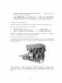
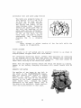
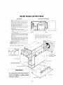
Photo
above
is
right
hand
side
of
WlOtwo
wi
th
2:
1
reverse
and
reduction
gear.
Note
convenient
cable
attachment
brackets
for
clutch
and
throttle,
accessible
filter
location
and
lube
oil
drain
hose.
11

REQUIREMENTS
FOR
PROPER OPERATION
LUBRICATION
SYSTEM
1.
Engine
oil
For
engine
lubrication,
use
diesel
engine
oil.
Diesel
engine
oils
are
classified
according
to
the
API
Specifications
into
grades
CA,
CB,
CC
and
CD.
Anyone
of
them
is
usable,
but
use
of
CC
or
higher
grades
prepared
by
well-known
makers
is
recommended.
2.
Engine
oil
viscosity
Use
oil
having
viscosity
best
suited
to
the
atmospheric
tem-
perature.
Use
of
an
all-season
oil
SAEIOW-30
with
minimum
visco-
sity
change
under
different
temperatures
is
suggested.
20·C
(6S·F)
or
higher
SAE
30
or
1~W-30
SAE
20
or
10W-30
S·C
(41·F)
or
lower
SAE
IOW-30
3.
Oil
pressure
The
oil
pressure
during
operation
of
the
engine
is
indicated
by
the
oil
pressure
gauge.
During
normal
operation
....•.•.....
Oil
pressure
will
range
between
50
and
70
PSI.
At
the
time
of
cranking
•........•..
Pressure
will
rise
proportion-
ately
with
speed.
4.
Engine
oil
change
To
renew
engine
oil,
discharge
old
oil
through
the
sump
drain
hose
attached
at
front
of
engine
while
engine
is
still
warm.
Drain
old
oil
completely,
replace
the
hose,
plug
the
end
securely
and add
fresh
oil
through
the
oil
inlet
port
on
the
valve
cover.
After
refilling
oil,
idle
the
engine
for
several
minutes
and
stop.
Then
check
the
quantity
of
oil
by
the
oil
level
gauge.
Fill
to
but
not
over
the
high
mark
on
the
dipstick.
Always
observe
old
oil
as
it
is
removed.
A
yellow/grey
emulsion
indicates
presence
of
water
in
the
oil.
While
this
condition
is
rare,
it
does
require
prompt
attention
to
prevent
serious
damage.
12

5.
Replacement
of
oil
filter
Being
a
replaceable
cartridge
type,
the
oil
fil
ter
requires
no
cleaning
inside.
In
installing
the
oil
filter,
apply
eng
ine
oil
th
inly
on
to
the
O-ring,
and
then
tighten
it
by
hand
firmly.
When
removing
the
used
fil
ter
,
cover
over
with
a
plastic
bag.
This
will
allow
both
filter
element
and
spilled
oil
to
be
collected
cleanly
without
spilling
oil
in
the
bilge.
Note
A:
Note
B:
After
market
filters
are
not
recommended
since
the
material
standard
or
diameters
of
important
items
might
be
entirely
different
from
genuine
parts.
Immediately
after
filter
change
and
oil
fill,
run
engine
to
ensure
that
oil
pressure
is
normal
and
that
there
are
no
oil
leaks.
FUEL
SYSTEM
1.
Diesel
fuel
2.
USE
#2
DIESEL FUEL.
NEVER
USE
KEROSENE
OR
HEAVY
OIL.
In
cold
weather
particularly,
water
vapor
is
produced
by
conden-
sation
when
air
is
present
in
the
fuel
tank.
The
tank,
therefore,
should
be
kept
full
as
much
as
possible.
The
fuel
tank,
furthermore,
needs
to
be
kept
completely
free
of
dirt
and
water.
It
is
required
that
a
primary
fuel
filter
of
the
water
entrapment
type
be
installed
betvleen
the
fuel
tank
and
the
eng
ine.
Such
a
fil
ter,
shovln
her
e,
is
avail
able
under
Par
t
#32974
from
your
local
Wester
beke
representati
ve
or
your
boat
builder.
rrhis
fil-
ter,
adapted
for
boat
builder
use,
comes
complete
wi
th
fi
t-
tings
for
either
hose
or
metal
tubing~
Mount
in
an
accessible
place,
inspect
often
and
drain
off
water
accumulation
fre~
quently
..
13
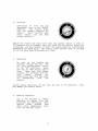
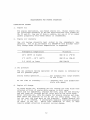
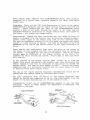
WATER LEVEI,
INDICATOR-
--~"
..
,,,,,~-,,-,,,,,,,,,-,,,-,,,-,,-
RING

3.
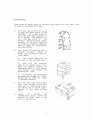
Notes
on
fuel
system
See
on
facing
page
a
typical
explode~
view
of
a
fuel
system
for
a
two
cylinder
engine.
It
is
also
illustrative
of
the
self-bleeding
system
used
on
the
Westerbeke
3
KW
marine
generator
set.
The
Westerbeke
self-bleeding
fuel
system
is
automatic
in
opera-
tion.
While
it
is
unlikely
that
the
operator
will
be
forced
to
service
the
system
at
sea,
the
possibility
does
exist.
Therefore,
it
is
recommended
that
the
following
parts
be
carried
onboard.
Banjo
washers
#'s
11,
30, 31,
33, 34,
45
Injector
seat
washers
#42
Lift
pump
filter
and
gaskets
#'s
6,
7,
8
Fuel
filter
element
and
gaskets
#'s
13,
14
,15
I f a
leak
should
develop
at
a
banjo
or
washer
that
cannot
be
remedied
by
a
simple
tightening
of
the
screw,
renew
the
washers.
The
engine
can
be
started
by
taking
the
steps
described
on
pages
8
and
9.
In
cases
where
the
engine
cannot
be
started
easily,
loosen
two
injection
nuts
on
the
nozzle
side,
turn
the
speed
control
lever
to
"full
open"
position,
turn
the
starter
motor
and
then
tighten
the
nuts
firmly.
4.
Cleaning
fuel
filter
and
replacing
filter
element
After
the
first
50
hours
of
operation,
loosen
the
retainer
ring
#16
and
discard
filter
element
#15.
Clean
bowl
#17
and
re-install
new
filter,
using
new
gasket
#13
and
#14.
This
same
treatment
is
required
of
the
filter
element
#6
in
the
fuel
lift
pump.
Similarly,
replace
new
filter
element
#6
using
new
gasket
#7
and
#8.
After
the
first
50
hour
change,
the
change
period
may
be
increased
to
200
hours
or
once
per
season.
5.
Fuel
injection
pump
The
fuel
injection
pump
is
one
of
the
most
important
components
of
the
diesel
engine
and
thus
it
calls
for
the
,utmost
caution
in
handling.
Furthermore,
the
fuel
injection
pump
has
been
thoroughly
shop-adjusted
and
should
never
be
readjusted
care-
lessly.
Such
adj
ustment,
whenever
necessary,
should
be
per
formed
at
an
authorized
service
station,
as
a
precision
pump
tester
and
skills
are
required.
To
obtain
long
and
satisfactory
use
of
your
injection
pump:
Always
use
fuel
which
is
free
from
impurities.
Clean
and
renew
the
fuel
filter
periodically.
Inspect
water
entrapment
filter
regularly.
14

If
a
water
trap
type
filter
(see
page
13)
is
not
interposed
bet-
ween
the
fuel
tank
and
engine
lift
pump,
any
entrained
water
will
tend
to
lay
in
bottom
of
lift
pump.
Internal
metal
parts
of
the
lift
pump
will
rust.
Particles
will
pass
on
to
filters
and
even-
tually
to
injection
pump
and
injectors
with
damaging
and
expensive
results.
While
many
boat
builders
do
supply
a
water
trap
filter,
there
are
some
who
do
not.
It
is
to
prevent
such
omission
that
Westerbeke
offers
a
sedimenter/water
trap
filter
as
a
desirable
optional
extra
at
moderate
cost.
It
is
supplied
with
fittings
for
either
hose
piping
or
metal
tube
piping.
Order
it
wi
th
the
eng
ine,
install
it
in
an
accessible
place,
inspect
it
daily
and
drain
as
needed.
15

10
Cooling
water
As
cooling
water,
use
soft
water
with
least
impurity
content
such
as
tap
water
(potable
water)
or
rainwater,
and
never
use
hard
water
or
foul
water~
Use
of
hard
water
or
water
containing
much
impurity
will
lead
to
collection
of
scale
in
the
engine
and
heat
exchanger
with
resultant
decline
in
cooling
effects.
2..
Antifreeze
In
cold
districts,
care
should
be
taken
to
prevent
cooling
water
from
freezing"
Cooling
water,
'itlhen
frozen,
expands
to
break
the
heat
exchanger
and
the
cylinder
block
f
and
it
is
essential
that
antifreeze
be
added
to
cooling
water
in
a
quantity
proportional
to
the
lUvlest
temperature
of
the
dist.rict..
It
is
recommended
that
the
antifreeze
mixture
be
used
throughout
the
yearo
*Antifreeze
of
poor
quality
or
without
rust
inhibitor
will
cause
corrosion
of
the
cooling
system.
Always
use
antifreeze
prepared
by
a
reliable
maker,
and
never
use
it
mixed
with
antifreeze
of
a
different
brand.
*Make
sure
that
the
cooling
system
of
the
engi.ne
is
cleaned
well
before
adding
antifreeze~
*Recommended
antifreeze
for.
year
round
use
is
ZEREX
or
PRE;STONE vIi
th
rust
inhibi
tor"
ANTIFREEZE ADDITION
DATA
Antifreeze
Concentration
%
13
23
30
35
45
50
60
--~--"""":"~-~""'-~."""~"""""-"-""~-~'''''''.'''~---''~'.'~-'
Freezing
..
c
-5
-10
-15
-20
-30
-40
-50
t
e.~.E.~E_a
t
~
r.
E:
C'
F)
(23)
(14)
(
5.)
(-4)
(-22)
(-40)
(-58)
Note:
It
is
advisa.ble
that
antifreeze
concen"tration
be
selected
on
the
basis
of
a
temperature
which
is
about
5«C
(106F)
lower
than
the
actual
atmospheric
tem-
pera.ture
expected
..
3.
Fresh
water
cooling
system
The
system
consists
of
a
sea
water
pump
which
pumps
raw
sea
water
through
a
heat
exchanger
to
remove
heat
from
the
coolant.
The
raw
water
is
discharged
overboard
through
the
exhaust
line$
The
engine
coolant
(fresh
water
with
or
without
antifreeze)
is
circulated
by
the
fresh
water
pump
in
continuous
circuit.,
pumped
through
the
cylinder
block,
cylinder
head,
heat
exchanger
and
back
to
the
fresh
water
pump.
16

The
total
system
is
very
reliable
and
requires
only
a
daily
check
of
the
water
level
in
the
system
plus
routine
check
of
hose
clamps
and
fittings.
It
is
likely
that
zinc
electrodes
will
waste
away
from
contact
with
sea
water.
It
is
also
possible
for
the
raw
water
pump
impeller
to
fail
due
to
lack
of
sea
water
or
deter
ioration..
An
early
sign
of
impeller
failure
is
less
water
and
more
steam
at
the
exhaust
through
hull
fitting.
It
is
recommended,
therefore,
that
zinc
electrodes
#11885,
water
pump
belt
#32942,
alternator
belt
#13585,
sea
water
pump
assembly
#32617
and
sea
water
impeller
kit
#32620
be
carried
onboard
at
all
times..
These
parts
should
be
ordered
from
your
nearest
stocking
dealer
and
used
as
inspection
dictates
..
17

Alternator
belt
and
water
pump
tension
The
belts
are
properly
tense
if
they
deflect
10
to
12
mm
(0.39
to
0.47
in)
as
they
are
de-
pressed
wi
th
a
finger
between
the
pulley
and
pulley
of
the
long
distance
side.
Excessi
ve
tension
can
cause
quick
wear
of
the
belt
and
bearings
of
the
water
pump
and
the
al
ternator.
Excessive
slackness
or
presence
of
oil
on
the
belt,
on
the
other
hand,
can
lead
to
engine
overheating
and
insufficient
charging
due
to
a
slipping
belt.
CAUTION:
Never
attempt
to
adjust
tension
of
the
fan
belt
while
the
engine
is
in
operation.
WIRING
DIAGRAM
Your
engine
is
of
12V
system
and
its
electric
circuit
is
as
shown
in
diagram
#24666
shipped
loose
with
this
manual.
For
installing
electrical
parts,
connect
them
correctly
by
referring
to
the
diagram
and
at
the
same
time
check
for
damaged
wire
sheathing
and
confirm
that
grounding
is
provided
properly.
Care
must
always
be
taken
while
working
on
the
electrical
system.
Never
shut
the
engine
battery
switch
off
while
the
engine
is
running.
Damage
to
the
battery
charging
alternator
will
result
should
this
be
done.
DOMESTIC
HOT
WATER
The
smaller
of
two
hoses
at
top
left
in
the
photo
is
the
FLOWCONTROLLER
bypass.
When
you
connect
your
eng
ine
to
supply
domestic
hot
water,
remove
the
bypass
hose,
connect
the
spud
on
the
thermostat
housing
to
the
lower
connection
on
the
water
heater
coil.
Connect
the
higher
connection
on
the
water
heater
coil
to
the
spud
on
the
manifold.
Study
instruc-
tions
and
illustrations
on
next
page.
18
Page is loading ...
Page is loading ...
Page is loading ...
Page is loading ...
Page is loading ...
Page is loading ...
Page is loading ...
Page is loading ...
Page is loading ...
Page is loading ...
Page is loading ...
Page is loading ...
Page is loading ...
Page is loading ...
Page is loading ...
Page is loading ...
Page is loading ...
Page is loading ...
-
 1
1
-
 2
2
-
 3
3
-
 4
4
-
 5
5
-
 6
6
-
 7
7
-
 8
8
-
 9
9
-
 10
10
-
 11
11
-
 12
12
-
 13
13
-
 14
14
-
 15
15
-
 16
16
-
 17
17
-
 18
18
-
 19
19
-
 20
20
-
 21
21
-
 22
22
-
 23
23
-
 24
24
-
 25
25
-
 26
26
-
 27
27
-
 28
28
-
 29
29
-
 30
30
-
 31
31
-
 32
32
-
 33
33
-
 34
34
-
 35
35
-
 36
36
-
 37
37
-
 38
38


Westerbeke 2.4 WMD - 50 Hz User manual
- Type
- User manual
Ask a question and I''ll find the answer in the document
Finding information in a document is now easier with AI
Related papers
-
Westerbeke 25.0 WMF - 60 Hz User manual
-
Westerbeke W 46 User manual
-
-
-
Westerbeke 4.4 WMD User manual
-
-
Universal M2-12A(C) User manual
-
Westerbeke W 21A User manual
-
Westerbeke 11.0 TWG User manual
-
Other documents
-
 Solé Diesel MINI-10 User manual
-
Hyundai u125 series Installation & Operation Manual
-
 John Deere rhino pd54 User manual
-
Ransomes 898810 Owner's manual
-
 Solé Diesel MINI-23 User manual
-
-
Nothern Lights M99C User manual
-
Kawasaki LTD 440 Assembly & Preparation Manual
-
Shibaura N843L User manual
-
Vetus m-line User manual


