Ransomes 62287, 62288, 62289, 62302, 62303, 62304, 62305, 62306 User manual
- Category
- Lawnmowers
- Type
- User manual

4
4247530-Rev A 4-1
Chapter 4
Electrical
Specifications . . . . . . . . . . . . . . . . . . . . . . . . . . . . . . . . . . . . . . . . . . . . . . . . . . . . . . . . . . . . . . . . . 4-3
Test and Adjustment Specifications . . . . . . . . . . . . . . . . . . . . . . . . . . . . . . . . . . . . . . . . . . . 4-3
Repair Specifications . . . . . . . . . . . . . . . . . . . . . . . . . . . . . . . . . . . . . . . . . . . . . . . . . . . . . . . 4-3
Theory and Diagnostic Information . . . . . . . . . . . . . . . . . . . . . . . . . . . . . . . . . . . . . . . . . . . . . . . 4-4
Electrical Component Symbols . . . . . . . . . . . . . . . . . . . . . . . . . . . . . . . . . . . . . . . . . . . . . . . 4-4
Electrical Schematic Component Identification . . . . . . . . . . . . . . . . . . . . . . . . . . . . . . . . . . . . . 4-7
Electrical Schematic—Diesel . . . . . . . . . . . . . . . . . . . . . . . . . . . . . . . . . . . . . . . . . . . . . . . . 4-8
Electrical Schematic—Gasoline . . . . . . . . . . . . . . . . . . . . . . . . . . . . . . . . . . . . . . . . . . . . . 4-10
Theory of Operation and Sub-Circuit Schematics . . . . . . . . . . . . . . . . . . . . . . . . . . . . . . . . . . 4-12
Power Circuit Diesel—Theory of Operation . . . . . . . . . . . . . . . . . . . . . . . . . . . . . . . . . . . . 4-12
Power Circuit Gasoline—Theory of Operation . . . . . . . . . . . . . . . . . . . . . . . . . . . . . . . . . . 4-13
Glow Plug Circuit—Theory of Operation . . . . . . . . . . . . . . . . . . . . . . . . . . . . . . . . . . . . . . . 4-14
Glow Plug Circuit Schematic . . . . . . . . . . . . . . . . . . . . . . . . . . . . . . . . . . . . . . . . . . . . . . . . 4-14
Start Circuit—Theory of Operation . . . . . . . . . . . . . . . . . . . . . . . . . . . . . . . . . . . . . . . . . . . 4-15
Start Circuit Schematic—Diesel . . . . . . . . . . . . . . . . . . . . . . . . . . . . . . . . . . . . . . . . . . . . . 4-16
Start Circuit Schematic—Gasoline . . . . . . . . . . . . . . . . . . . . . . . . . . . . . . . . . . . . . . . . . . . 4-17
Charging Circuit—Theory of Operation . . . . . . . . . . . . . . . . . . . . . . . . . . . . . . . . . . . . . . . . 4-18
Charging Circuit Schematic—Diesel . . . . . . . . . . . . . . . . . . . . . . . . . . . . . . . . . . . . . . . . . . 4-19
Charging Circuit Schematic—Gasoline . . . . . . . . . . . . . . . . . . . . . . . . . . . . . . . . . . . . . . . . 4-20
Run Circuit Diesel—Theory of Operation . . . . . . . . . . . . . . . . . . . . . . . . . . . . . . . . . . . . . . 4-21
Run Circuit Schematic Diesel—On Seat . . . . . . . . . . . . . . . . . . . . . . . . . . . . . . . . . . . . . . . 4-22
Run Circuit Schematic Diesel—Off Seat . . . . . . . . . . . . . . . . . . . . . . . . . . . . . . . . . . . . . . . 4-23
Run Circuit Gasoline—Theory of Operation . . . . . . . . . . . . . . . . . . . . . . . . . . . . . . . . . . . . 4-24
Run Circuit Schematic Gasoline—On Seat . . . . . . . . . . . . . . . . . . . . . . . . . . . . . . . . . . . . . 4-25
Run Circuit Schematic Gasoline—Off Seat . . . . . . . . . . . . . . . . . . . . . . . . . . . . . . . . . . . . . 4-26
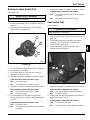
Backlap Circuit—Theory of Operation . . . . . . . . . . . . . . . . . . . . . . . . . . . . . . . . . . . . . . . . . 4-27
Backlap Circuit Schematic—Diesel . . . . . . . . . . . . . . . . . . . . . . . . . . . . . . . . . . . . . . . . . . . 4-28
Backlap Circuit Schematic—Gasoline . . . . . . . . . . . . . . . . . . . . . . . . . . . . . . . . . . . . . . . . . 4-29
Instrumentation Circuit—Theory of Operation . . . . . . . . . . . . . . . . . . . . . . . . . . . . . . . . . . . 4-30
Instrumentation Circuit Schematic—Diesel . . . . . . . . . . . . . . . . . . . . . . . . . . . . . . . . . . . . . 4-31
Instrumentation Circuit Schematic—Gasoline . . . . . . . . . . . . . . . . . . . . . . . . . . . . . . . . . . . 4-32
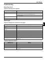
Troubleshooting . . . . . . . . . . . . . . . . . . . . . . . . . . . . . . . . . . . . . . . . . . . . . . . . . . . . . . . . . . . . . . 4-33
Glow Plug Circuit . . . . . . . . . . . . . . . . . . . . . . . . . . . . . . . . . . . . . . . . . . . . . . . . . . . . . . . . . 4-33
Start Circuit . . . . . . . . . . . . . . . . . . . . . . . . . . . . . . . . . . . . . . . . . . . . . . . . . . . . . . . . . . . . . 4-33
Charging Circuit . . . . . . . . . . . . . . . . . . . . . . . . . . . . . . . . . . . . . . . . . . . . . . . . . . . . . . . . . . 4-34
Run Circuit . . . . . . . . . . . . . . . . . . . . . . . . . . . . . . . . . . . . . . . . . . . . . . . . . . . . . . . . . . . . . . 4-34
Backlap Circuit . . . . . . . . . . . . . . . . . . . . . . . . . . . . . . . . . . . . . . . . . . . . . . . . . . . . . . . . . . 4-34
Instrumentation Circuit . . . . . . . . . . . . . . . . . . . . . . . . . . . . . . . . . . . . . . . . . . . . . . . . . . . . 4-35

4-2 4247530-Rev A
ELECTRICAL
4
Component Testing . . . . . . . . . . . . . . . . . . . . . . . . . . . . . . . . . . . . . . . . . . . . . . . . . . . . . . . . . . . 4-37
Electrical System and Component Testing . . . . . . . . . . . . . . . . . . . . . . . . . . . . . . . . . . . . . 4-37
Fuse Test . . . . . . . . . . . . . . . . . . . . . . . . . . . . . . . . . . . . . . . . . . . . . . . . . . . . . . . . . . . . . . . 4-38
Engine Stop Relay Test (Gasoline) . . . . . . . . . . . . . . . . . . . . . . . . . . . . . . . . . . . . . . . . . . . 4-38
Time Delay Relay Test . . . . . . . . . . . . . . . . . . . . . . . . . . . . . . . . . . . . . . . . . . . . . . . . . . . . 4-39
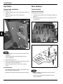
Micro Switch Test . . . . . . . . . . . . . . . . . . . . . . . . . . . . . . . . . . . . . . . . . . . . . . . . . . . . . . . .4-39
Glow Plug Switch Test . . . . . . . . . . . . . . . . . . . . . . . . . . . . . . . . . . . . . . . . . . . . . . . . . . . . . 4-40
Key Switch Test . . . . . . . . . . . . . . . . . . . . . . . . . . . . . . . . . . . . . . . . . . . . . . . . . . . . . . . . . . 4-40
Backlap Lockout Switch Test . . . . . . . . . . . . . . . . . . . . . . . . . . . . . . . . . . . . . . . . . . . . . . . . 4-41
Seat Switch Test . . . . . . . . . . . . . . . . . . . . . . . . . . . . . . . . . . . . . . . . . . . . . . . . . . . . . . . . . 4-41
Start Solenoid Test (Diesel) . . . . . . . . . . . . . . . . . . . . . . . . . . . . . . . . . . . . . . . . . . . . . . . . . 4-42
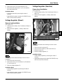
Voltage Regulator Test (Diesel) . . . . . . . . . . . . . . . . . . . . . . . . . . . . . . . . . . . . . . . . . . . . . . 4-42
Fuel Shutoff Solenoid Test (Diesel) . . . . . . . . . . . . . . . . . . . . . . . . . . . . . . . . . . . . . . . . . . . 4-43
Carb Solenoid Test (Gasoline) . . . . . . . . . . . . . . . . . . . . . . . . . . . . . . . . . . . . . . . . . . . . . . 4-44
Repair . . . . . . . . . . . . . . . . . . . . . . . . . . . . . . . . . . . . . . . . . . . . . . . . . . . . . . . . . . . . . . . . . . . . . . 4-45
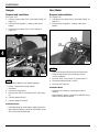
Battery . . . . . . . . . . . . . . . . . . . . . . . . . . . . . . . . . . . . . . . . . . . . . . . . . . . . . . . . . . . . . . . . . 4-45
Alternator (Diesel) . . . . . . . . . . . . . . . . . . . . . . . . . . . . . . . . . . . . . . . . . . . . . . . . . . . . . . . . 4-45
Starter Motor (Diesel) . . . . . . . . . . . . . . . . . . . . . . . . . . . . . . . . . . . . . . . . . . . . . . . . . . . . .4-46
Starter Motor (Gasoline) . . . . . . . . . . . . . . . . . . . . . . . . . . . . . . . . . . . . . . . . . . . . . . . . . . . 4-46
Instrument Panel . . . . . . . . . . . . . . . . . . . . . . . . . . . . . . . . . . . . . . . . . . . . . . . . . . . . . . . . . 4-47
Key Switch . . . . . . . . . . . . . . . . . . . . . . . . . . . . . . . . . . . . . . . . . . . . . . . . . . . . . . . . . . . . . . 4-48
Micro Switches . . . . . . . . . . . . . . . . . . . . . . . . . . . . . . . . . . . . . . . . . . . . . . . . . . . . . . . . . . . 4-48
Glow Plug Switch . . . . . . . . . . . . . . . . . . . . . . . . . . . . . . . . . . . . . . . . . . . . . . . . . . . . . . . . .4-50
Backlap Lockout Switch . . . . . . . . . . . . . . . . . . . . . . . . . . . . . . . . . . . . . . . . . . . . . . . . . . . . 4-51
Warning Lights . . . . . . . . . . . . . . . . . . . . . . . . . . . . . . . . . . . . . . . . . . . . . . . . . . . . . . . . . . . 4-51
Fuse and Fuse Holder . . . . . . . . . . . . . . . . . . . . . . . . . . . . . . . . . . . . . . . . . . . . . . . . . . . . . 4-52
Engine Stop Relay (Gasoline) . . . . . . . . . . . . . . . . . . . . . . . . . . . . . . . . . . . . . . . . . . . . . . . 4-53
Time Delay Relay . . . . . . . . . . . . . . . . . . . . . . . . . . . . . . . . . . . . . . . . . . . . . . . . . . . . . . . .4-54
Start Solenoid (Diesel) . . . . . . . . . . . . . . . . . . . . . . . . . . . . . . . . . . . . . . . . . . . . . . . . . . . . .4-54
Voltage Regulator (Diesel) . . . . . . . . . . . . . . . . . . . . . . . . . . . . . . . . . . . . . . . . . . . . . . . . . . 4-55
Voltage Regulator (Gasoline) . . . . . . . . . . . . . . . . . . . . . . . . . . . . . . . . . . . . . . . . . . . . . . . 4-55
Gauges . . . . . . . . . . . . . . . . . . . . . . . . . . . . . . . . . . . . . . . . . . . . . . . . . . . . . . . . . . . . . . . . 4-56
Hour Meter . . . . . . . . . . . . . . . . . . . . . . . . . . . . . . . . . . . . . . . . . . . . . . . . . . . . . . . . . . . . . . 4-56
Fuel Shutoff Solenoid (Diesel) . . . . . . . . . . . . . . . . . . . . . . . . . . . . . . . . . . . . . . . . . . . . . . . 4-57
Engine Oil Pressure Switch (Diesel) . . . . . . . . . . . . . . . . . . . . . . . . . . . . . . . . . . . . . . . . . . 4-57
Engine Oil Pressure Switch (Gasoline) . . . . . . . . . . . . . . . . . . . . . . . . . . . . . . . . . . . . . . . . 4-58
Engine Temperature Sensor (Diesel) . . . . . . . . . . . . . . . . . . . . . . . . . . . . . . . . . . . . . . . . . 4-58

ELECTRICAL
4247530-Rev A 4-3
4
Specifications
Test and Adjustment Specifications
Repair Specifications
Specification
Resistance Across Fuel Shutoff Pull-In Coil at 68° F ohm 0.5 ± 10%
Resistance Across Fuel Shutoff Hold-In Coil at 68° F
ohms 13.5 ± 10%
Resistance Across Carb Solenoid Coil at 68° F
ohms 40 ± 10%
Specification
Starter Mounting Screw Torque
(Diesel)
lb-ft (N·m) 17–21 (23–28)

4-4 4247530-Rev A
ELECTRICAL
4
Theory and Diagnostic
Information
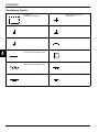
Electrical Component Symbols
The following symbols are used in the electrical
schematics to represent various electrical components.
Switches
1
1 The sample switch symbols shown are just a few of the many switch configurations. Switches are
designated by the number of “poles” (circuits controlled) and “throws” (actuator positions). Unless otherwise
specified, switches are shown in the “Normally Open” (N.O.) position.
Single Pole, Single Throw
(SPST)
Double Pole, Single Throw
(DPST)
Single Pole, Double Throw
(SPDT)
Double Pole, Double Throw
(DPDT)
Proximity Switch
Switching Devices
Temperature Switch Pressure Switch
Relay
Circuit Protection Devices
Fuse Circuit Breaker
N.O.
Blk Wht
(+)
t˚
P
87 87A85
86 30

ELECTRICAL
4247530-Rev A 4-5
4
Motors and Generating Devices
Electric Motors (may also
include “AC” or “DC.”)
Stator
Alternator
Actuating Devices
Solenoid Valve PTO Clutch
Engine-Related Devices
Ignition Coil Spark Plug
Regulator Fuel Shutoff Solenoid
Lights
Single-Element Light Dual-Element Light
M
G
G
U
3
U
Hold-In
Coil
Pull-In
Coil

4-6 4247530-Rev A
ELECTRICAL
4
Miscellaneous Symbols
Enclosure
(cabinet, housing, etc.)
Wires (crossing but not
connected)
Ground (to earth) Wiring Connections
Ground (to chassis) Coil
Direct Current (DC)
(as shown on an oscilloscope)
Battery
Alternating Current (AC)
(as shown on an oscilloscope)
Diode
Resistor Pin and Socket Connector
(+)
(-)

ELECTRICAL
4247530-Rev A 4-7
4
Electrical Schematic Component Identification
Electrical components shown in the main schematic are identified with an alphanumeric callout. All electrical
components shown in the electrical schematic are listed below.
• B1—Engine Oil Pressure Switch (See Figures 4-2
and 4-4.)
• B2—Engine Temperature Sensor (See Figure 4-2.)
• E1—Park Brake Light (See Figures 4-2 and 4-4.)
• E2—Engine Oil Pressure Light (See Figures 4-2 and
4-4.)
• F1—30A Fuse (Diesel) (See Figure 4-1.)
• F2—30A Fuse (Diesel) (See Figure 4-1.)\
• F3—6A Fuse (See Figures 4-1 and 4-3.)
• F4—20A Fuse (Gasoline) (See Figure 4-3.)
• G1—12V Battery (See Figures 4-1 and 4-3.)
• G2—Alternator (See Figure 4-1.)
• G3—Stator (See Figure 4-3.)
• H1—Volt Meter (See Figures 4-2 and 4-4.)
• H2—Engine Temperature Gauge (See Figure 4-2.)
• H3—Hour Meter (See Figures 4-2 and 4-4.)
• J1—Optional Light Connector (See Figures 4-1 and
4-3.)
• K1—Start Solenoid (Diesel) (See Figure 4-1.)
• K2—Time Delay Relay (Diesel) (See Figure 4-2.)
• K2—Engine Stop Relay (Gasoline) (See Figure 4-3.)
• M1—Starter Motor (See Figures 4-1 and 4-3.)
• N1—Voltage Regulator (See Figures 4-1 and 4-3.)
• R1—Glow Plugs (See Figure 4-1.)
• S1—Key Switch (See Figures 4-1 and 4-3.)
• S2—Glow Plug Switch (See Figure 4-1.))
• S3—Seat Switch (See Figures 4-2 and 4-4.)
• S4—Backlap Lockout Switch (See Figures 4-2 and
4-4.)
• S5—Traction Switch (See Figures 4-2 and 4-4.)
• S6—Brake Switch (See Figures 4-2 and 4-4.)
• S7—Mow Switch (See Figures 4-2 and 4-4.)
• S8—Backlap Switch (See Figures 4-2 and 4-4.)
• S9—Park Brake Light Switch (See Figures 4-2 and
4-4.)
• Y1—Fuel Shutoff Solenoid (Diesel) (See Figure 4-1.)
• Y2—Carb Solenoid (Gasoline) (See Figure 4-3.)

4-8 4247530-Rev A
ELECTRICAL
4
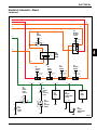
Electrical Schematic—Diesel
See Figures 4-1 and 4-2.
Figure 4-1
Wht
Grn
Grn
Pur
Gry
Pur
Red
Red Red
Red
Wht
Wht
Blk
Red
Red
M1
Starter
Motor
Grn
R1
Glow
Plugs
M
S1
Key
Switch
G1
12V
Battery
Gry
BrnBrn
Brn
Org
Org
Blk
Org
Org
Blu
Blu
Org
Org
Red
BluBlu
Blu Blu
Yel Yel
Off
Run
Start
B
X
I
S
A
Y
(+)
(-)
Wht
Y1
Fuel
Shutoff
Solenoid
Red
Red
Red
Pur
Pnk
Pnk Pnk
Pur
Blk
Wht
K1
Start
Solenoid
Grn
On
Off
S2
Glow
Plug
Switch
WhtWhtWht
F3
6A
Fuse
F2
30A
Fuse
AC
AC B+
G
G2
Alternator
B+
N1
Voltage
Regulator
J1
Optional
Light
Connector
Unswitched Power Circuit
Switched Power Circuit
Interlock Circuit
Ground Circuit
Blk
8630
8587
Red
Red
F1
30A
Fuse
Hold-InPull-In
Blk
TN3337A

ELECTRICAL
4247530-Rev A 4-9
4
Electrical Schematic—Diesel
Continued
Figure 4-2
Blu
Yel Yel
Yel
YelYel
YelYel
Yel
Yel
Yel
(B)
(L) (G)
(S)
Yel
Brn Brn
Brn
Brn
Gry
Gry Gry Gry Gry Gry
Gry
Gry Gry
Gry
Gry Pur
PurGry
GryGry
Gry
Blk
Pnk
Yel Yel
On
Off
S3
Seat
Switch
S9
Park
Brake
Light
Switch
On
Off
Blu
B
L
G
M
Mow
Backlap
S4
Backlap
Lockout
Switch
K2
Time
Delay
Relay
WhtWht
WhtWht
Blk
Output Gnd
Enable+12V
1 Sec.
Off Delay
E2
Engine
Oil
Pressure
Light
E1
Park
Brake
Light
Blk
B1
Engine
Oil
Pressure
Switch
P
Blu
Blu
+12V
Gnd
H3
Hour
Meter
Blk
B2
Engine
Temperature
Sensor
Blk
+12V
SignalGnd
H2
Engine
Temperature
Gauge
Blk
+12V
Gnd
H1
Volt
Meter
Grn
Grn
Pnk
Locked
Released
S6
Brake
Switch
Pnk
Neutral
Engaged
S5
Traction
Switch
Neutral/
Reverse
Forward
S7
Mow
Switch
Pnk
Neutral/
Forward
Reverse
S8
Backlap
Switch
Pnk Blu
TN3338

4-10 4247530-Rev A
ELECTRICAL
4
Electrical Schematic—Gasoline
See Figures 4-3 and 4-4.
Figure 4-3
Pur
Pur
Pur
Pur
Red
Pur
BrnBrn
Brn
Blk
Red
Pnk/Wht
Pnk/Wht Pnk/Wht
Yel Yel
Red
Org
Org Org
YelYel
F3
6A
Fuse
J1
Optional
Light
Connector
Ignition
Module
Ignition
Module
Wht
Wht
Blk Pur
Blu
Blu
Blk
Blk
K2
Engine
Stop
Relay
Y2
Carb
Solenoid
8787A 85
8630
S1
Key
Switch
Off
Run
Start
B
X
I
S
A
Y
Unswitched Power Circuit
Switched Power Circuit
Interlock Circuit
Ground Circuit
Red
Red
Blk
G1
12V
Battery
Red
(+)
(-)
Pur
Pur
Red
Pur
F4
20A
Fuse
AC
AC
G
G3
Stator
Output (+)
N1
Voltage
Regulator
Grn
M1
Starter
Motor
M
TN3339

ELECTRICAL
4247530-Rev A 4-11
4
Electrical Schematic—Gasoline
Continued
Figure 4-4
Pnk/Wht
Yel
Yel
YelYel
Brn Brn
Brn
Pur
Pur Pur Pur Pur Pur
Pur
Pur Pur
Gry Pur
PurPur
Pur
Blk
Org
Yel Yel
On
Off
S3
Seat
Switch
S9
Park
Brake
Light
Switch
On
Off
Pnk/Wht
B
L
G
M
Mow
Backlap
S4
Backlap
Lockout
Switch
Yel
E2
Engine
Oil
Pressure
Light
E1
Park
Brake
Light
Blk
B1
Engine
Oil
Pressure
Switch
P
Blu/
Wht
Blu/
Wht
+12V
Gnd
H3
Hour
Meter
Blk
Blk
+12V
Gnd
H1
Volt
Meter
Unswitched Power Circuit
Switched Power Circuit
Interlock Circuit
Ground Circuit
Org
Locked
Released
S6
Brake
Switch
Pnk
Neutral
Engaged
S5
Traction
Switch
Neutral/
Reverse
Forward
S7
Mow
Switch
Pnk
Neutral/
Forward
Reverse
S8
Backlap
Switch
Pnk Blu
TN3340

4-12 4247530-Rev A
ELECTRICAL
4
Theory of Operation and
Sub-Circuit Schematics
Power Circuit Diesel—Theory of
Operation
Reference electrical schematic. See Figures 4-1 and 4-2.
Unswitched Power Circuit
Unswitched power is provided from the battery positive
terminal to the starter motor battery terminal and then
from the starter motor battery terminal to the start
solenoid terminal 30. Start solenoid terminal 30 provides
unswitched power to the key switch terminal X. Junction
at key switch terminal X provides unswitched power to 6A
fuse F3. Unswitched power is provided from 6A fuse F3
to the traction and backlap lockout switches.
The starter motor battery terminal also provides
unswitched power through 30A fuse F1 to the glow plug
switch.
Interlock Circuit
The interlock circuit provides voltage to the key switch.
The following must occur before the key switch is
provided with voltage:
• Traction switch in the neutral position
• Brake switch in the locked position
• Mow switch in the neutral position
• Backlap switch in the neutral position
With the traction switch in the neutral position, voltage is
provided from the traction switch to the brake switch.
With the brake switch in the locked position, voltage is
provided from the brake switch to the mow switch.
With the mow switch in the neutral position, voltage is
provided from the mow switch to the backlap switch.
With the backlap switch in the neutral position, voltage is
provided from the backlap switch to the key switch
terminal B.
Switched Power Circuit
When the key switch is turned to the run position, voltage
is provided from key switch terminal I to the fuel shutoff
solenoid hold-in coil. Key switch terminal I also provides
voltage to the following:
• Park brake light switch
• Engine oil pressure light
• Volt meter
• Engine temperature gauge
• Hour meter
With voltage provided to the hour meter, the hour meter
starts logging hours.
With the key switch in the run position and the engine
operating, the voltage regulator provides voltage to key
switch terminal Y through 30A fuse F2. Key switch
terminal X provides voltage to start solenoid terminal 30
and then to the starter motor battery terminal. Voltage is
provided from the starter motor battery terminal to the
battery positive terminal. (See “Charging Circuit—Theory
of Operation” on page 4-18.)
Key switch terminal Y also provides voltage to the
optional light connector.

ELECTRICAL
4247530-Rev A 4-13
4
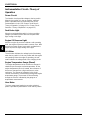
Power Circuit Gasoline—Theory of
Operation
Reference electrical schematic. See Figures 4-3 through
4-4.
Unswitched Power Circuit (Gasoline)
Unswitched power is provided from the battery positive
terminal to the starter motor battery terminal and then
from the starter motor battery terminal to key switch
terminal X. The starter motor battery terminal provides
unswitched power to 6A fuse F3. Unswitched power is
provided from 6A fuse F3 to the traction and seat
switches.
When the engine is operating, the voltage regulator
provides voltage to the starter motor battery terminal
through 20A fuse F4 and then to the battery. (See
“Charging Circuit—Theory of Operation” on page 4-18.)
Interlock Circuit
The interlock circuit provides voltage to the key switch.
The following must occur before the key switch is
provided with voltage:
• Traction switch in the neutral position
• Brake switch in the locked position
• Mow switch in the neutral position
• Backlap switch in the neutral position
With the traction switch in the neutral position, voltage is
provided from the traction switch to the brake switch.
With the brake switch in the locked position, voltage is
provided from the brake switch to the mow switch.
With the mow switch in the neutral position, voltage is
provided from the mow switch to the backlap switch.
With the backlap switch in the neutral position, voltage is
provided from the backlap switch to key switch terminal
B.
Switched Power Circuit
When the key switch is turned to the run position, voltage
is provided from key switch terminal I to the carb solenoid
and engine stop relay terminal 86. Key switch terminal I
also provides voltage to the following:
• Park brake light switch
• Engine oil pressure light
• Volt meter
• Hour meter
With voltage provided to the hour meter, the hour meter
starts logging hours.
With the key switch in the run position, key switch
terminal Y provides voltage to the optional light
connector.

4-14 4247530-Rev A
ELECTRICAL
4
Glow Plug Circuit—Theory of
Operation
Unswitched Power Circuit
The starter motor battery terminal provides unswitched
power through 30A fuse F1 to the glow plug switch.
Glow Plug Circuit
When the glow plug switch is held in the on position,
voltage is provided to the glow plugs, heating the glow
plugs.
Glow Plug Circuit Schematic
See Figure 4-5.
Figure 4-5
Blk
Red Red
Red
M1
Starter
Motor
Grn
R1
Glow
Plugs
M
G1
12V
Battery
Red
(+)
(-)
Grn
On
Off
S2
Glow
Plug
Switch
Unswitched Power Circuit
Glow Plug Circuit
Ground Circuit
Red
Red
F1
30A
Fuse
TN3359

ELECTRICAL
4247530-Rev A 4-15
4
Start Circuit—Theory of Operation
Interlock Circuit
The interlock circuit provides voltage to the key switch.
The following must occur before the key switch is
provided with voltage:
• Traction switch in the neutral position
• Brake switch in the locked position
• Mow switch in the neutral position
• Backlap switch in the neutral position
With the traction switch in the neutral position, voltage is
provided from the traction switch to the brake switch.
With the brake switch in the locked position, voltage is
provided from the brake switch to the mow switch.
With the mow switch in the neutral position, voltage is
provided from the mow switch to the backlap switch.
With the backlap switch in the neutral position, voltage is
provided from the backlap switch to the key switch
terminal B.
Start Circuit (Diesel)
When the key switch is turned to the run position, voltage
is provided from key switch terminal I to the fuel shutoff
hold-in coil.
When the key switch is turned to the start position,
voltage is provided from key switch terminal S to the start
solenoid, energizing the solenoid. With the start solenoid
energized, voltage is provided from start solenoid
terminal 87 to the starter motor solenoid, energizing the
solenoid. With the starter motor solenoid energized,
voltage is provided from the starter motor solenoid
contacts to the starter motor, engaging the motor.
The starter solenoid contacts also provide voltage to the
fuel shutoff solenoid pull-in coil, energizing the coil. With
the pull-in coil energized, the solenoid plunger retracts.
The hold-in coil keeps the solenoid plunger in the
retracted position until it is de-energized. With the
solenoid plunger retracted, fuel is allowed to flow, and as
the starter motor cranks the engine, the engine starts
operating.
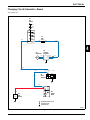
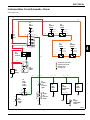
Start Circuit (Gasoline)
When the key switch is in the run position, key switch
terminal I provides voltage to the carb solenoid,
energizing the solenoid. With the solenoid energized, the
carb solenoid plunger retracts, allowing fuel to flow.
With the key switch in the run position, key switch
terminal I also provides voltage to engine stop relay
terminal 86, energizing the relay. With the relay
energized, the engine stop relay un-grounds the ignition
modules, allowing the modules to produce spark when
the engine is turning.
When the key switch is turned to the start position,
voltage is provided from key switch terminal S to the
starter motor solenoid, energizing the solenoid. With the
starter motor solenoid energized, voltage is provided
from the starter motor solenoid contacts to the starter
motor, engaging the motor.

4-16 4247530-Rev A
ELECTRICAL
4
Start Circuit Schematic—Diesel
See Figure 4-6.
Figure 4-6
Wht
Grn
Grn
Pur Pur
Red
Red
Wht
Wht
Blk
Red
M1
Starter
Motor
M
S1
Key
Switch
G1
12V
Battery
Red
BluBlu
Blu Blu
Off
Run
Start
B
X
I
S
A
Y
(+)
(-)
Red
Red
Red
Pur
Pnk
Pnk Pnk
Wht
K1
Start
Solenoid
F3
6A
Fuse
Pnk
Locked
Released
S6
Brake
Switch
Pnk
Neutral
Engaged
S5
Traction
Switch
Pnk
Neutral/
Reverse
Forward
S7
Mow
Switch
Pnk
Neutral/
Forward
Reverse
S8
Backlap
Switch
Pnk Blu
Unswitched Power Circuit
Switched Power Circuit
Interlock Circuit
Ground Circuit
Start Circuit
Fuel Pull-In Circuit
Blk
8630
8587
Wht
Y1
Fuel
Shutoff
Solenoid
Pur
Hold-InPull-In
Blk
TN3363

ELECTRICAL
4247530-Rev A 4-17
4
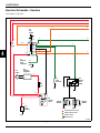
Start Circuit Schematic—Gasoline
See Figure 4-7.
Figure 4-7
Pur
Pur Pur
Pnk/Wht
Pnk/Wht Pnk/Wht
Org
Red
Org
F3
6A
Fuse
Ignition
Module
Ignition
Module
Wht
Wht
Blk Pur
Blu
Blk
Blk
K2
Engine
Stop
Relay
Y2
Carb
Solenoid
8787A 85
8630
S1
Key
Switch
Off
Run
Start
B
X
I
S
A
Y
Org
Locked
Released
S6
Brake
Switch
Pnk
Neutral
Engaged
S5
Traction
Switch
Pnk
Neutral/
Reverse
Forward
S7
Mow
Switch
Pnk
Neutral/
Forward
Reverse
S8
Backlap
Switch
Pnk Pnk/Wht
Unswitched Power Circuit
Switched Power Circuit
Start Circuit
Interlock Circuit
Ground Circuit
Red
Red
Blk
G1
12V
Battery
Red
(+)
(-)
M1
Starter
Motor
M
TN3364

4-18 4247530-Rev A
ELECTRICAL
4
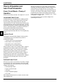
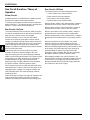
Charging Circuit—Theory of
Operation
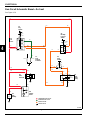
Charging Circuit (Diesel)
The charging circuit is an alternator with a external
voltage regulator design. As the alternator turns, the
alternator produces AC voltage. The AC voltage is
rectified by the voltage regulator, and DC voltage is
produced. The DC voltage is used to charge the battery.
When the battery voltage is low, the voltage regulator
supplies regulated voltage to charge the battery. When
the battery is fully charged, the regulator stops providing
regulated voltage to the battery.
With the key switch in the run position, the voltage
regulator provides voltage to key switch terminal Y
through 30A fuse F2. Key switch terminal X provides
voltage to start solenoid terminal 30 and then to the
starter motor battery terminal. Voltage is provided from
the starter motor battery terminal to the battery positive
terminal.
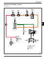
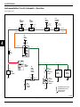
Charging Circuit (Gasoline)
The charging circuit is a permanent magnet and stator
design. As the flywheel turns, the magnets pass the
stator coils, producing AC voltage. The AC voltage is
rectified by the voltage regulator, and DC voltage is
produced. The DC voltage is used to charge the battery.
When the battery voltage is low, the voltage regulator
supplies regulated voltage to charge the battery. When
the battery is fully charged, the regulator stops providing
regulated voltage to the battery.
The voltage regulator provides voltage to the starter
motor battery terminal through 20A fuse F4 and then to
the battery.

ELECTRICAL
4247530-Rev A 4-19
4
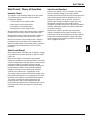
Charging Circuit Schematic—Diesel
See Figure 4-8.
Figure 4-8
Red
Red Red
Blk
Red
M1
Starter
Motor
M
S1
Key
Switch
G1
12V
Battery
Org Org Org
Org
Blu
Blu
Org
Org
Red
Off
Run
Start
B
X
I
S
A
Y
(+)
(-)
Red
Red
Red
Blk
Blk
Wht
K1
Start
Solenoid
F2
30A
Fuse
AC
AC B+
G
G2
Alternator
B+
N1
Voltage
Regulator
Unswitched Power Circuit
Charging Circuit
Ground Circuit
TN3357

4-20 4247530-Rev A
ELECTRICAL
4
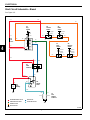
Charging Circuit Schematic—Gasoline
See Figure 4-9.
Figure 4-9
Unswitched Power Circuit
Charging Circuit
Ground Circuit
Red
Blk
G1
12V
Battery
Red
(+)
(-)
Pur Pur
Red
Pur
F4
20A
Fuse
AC
AC
G
G3
Stator
Output (+)
N1
Voltage
Regulator
M1
Starter
Motor
M
TN3358
Page is loading ...
Page is loading ...
Page is loading ...
Page is loading ...
Page is loading ...
Page is loading ...
Page is loading ...
Page is loading ...
Page is loading ...
Page is loading ...
Page is loading ...
Page is loading ...
Page is loading ...
Page is loading ...
Page is loading ...
Page is loading ...
Page is loading ...
Page is loading ...
Page is loading ...
Page is loading ...
Page is loading ...
Page is loading ...
Page is loading ...
Page is loading ...
Page is loading ...
Page is loading ...
Page is loading ...
Page is loading ...
Page is loading ...
Page is loading ...
Page is loading ...
Page is loading ...
Page is loading ...
Page is loading ...
Page is loading ...
Page is loading ...
Page is loading ...
Page is loading ...
-
 1
1
-
 2
2
-
 3
3
-
 4
4
-
 5
5
-
 6
6
-
 7
7
-
 8
8
-
 9
9
-
 10
10
-
 11
11
-
 12
12
-
 13
13
-
 14
14
-
 15
15
-
 16
16
-
 17
17
-
 18
18
-
 19
19
-
 20
20
-
 21
21
-
 22
22
-
 23
23
-
 24
24
-
 25
25
-
 26
26
-
 27
27
-
 28
28
-
 29
29
-
 30
30
-
 31
31
-
 32
32
-
 33
33
-
 34
34
-
 35
35
-
 36
36
-
 37
37
-
 38
38
-
 39
39
-
 40
40
-
 41
41
-
 42
42
-
 43
43
-
 44
44
-
 45
45
-
 46
46
-
 47
47
-
 48
48
-
 49
49
-
 50
50
-
 51
51
-
 52
52
-
 53
53
-
 54
54
-
 55
55
-
 56
56
-
 57
57
-
 58
58


Ransomes 62287, 62288, 62289, 62302, 62303, 62304, 62305, 62306 User manual
- Category
- Lawnmowers
- Type
- User manual
Ask a question and I''ll find the answer in the document
Finding information in a document is now easier with AI
Related papers
-
Ransomes 67923, 67924, 67938, 67955, 67956, 67957 User manual
-
-
-
-
-
-
-
Ransomes Eclipse 322 62803 User manual
-
Textron 68080 User manual
-
Other documents
-
Speed Queen SLW570RAW Datasheet
-
Amana PALW540RMW1 Datasheet
-
-
Harper ATM 72LC Owner's manual
-
-
Tennant 7200 Instruction Bulletin
-
Toro 244-5 Yard Tractor User manual
-
-
AEM 30-3821 Operating instructions
-
Panduit Model PN60B User manual