Extron AXP 64 C AT User manual

Category
Serial switch boxes
Type
User manual

Extron AXP 64 C AT is a versatile audio expansion processor designed to enhance audio capabilities in various professional environments. With its digital and analog connectivity options, it provides flexible signal routing and processing for up to 56 channels of Dante audio. The device features six balanced/unbalanced microphone or mono line level inputs with 48-volt phantom power for the first four inputs. Four balanced/unbalanced mono line level or two stereo outputs offer versatile connectivity for audio distribution.

Extron AXP 64 C AT is a versatile audio expansion processor designed to enhance audio capabilities in various professional environments. With its digital and analog connectivity options, it provides flexible signal routing and processing for up to 56 channels of Dante audio. The device features six balanced/unbalanced microphone or mono line level inputs with 48-volt phantom power for the first four inputs. Four balanced/unbalanced mono line level or two stereo outputs offer versatile connectivity for audio distribution.

1
Product Category
IMPORTANT:
Refer to www.extron.com for the
complete user guide and installation
instructions befor
e connecting the
pr
oduct to the power sour
ce.
This guide provides basic instructions for an experienced technician
to install the AXP64 CAT Audio Expansion Processor. For additional
information and specications, see the AXP64 CAT product page at
www.extron.com.
AXP64CAT • Setup Guide
Disconnecting Power and Mounting the AXP64CAT
Before beginning installation, disconnect power to the AXP64CAT and turn off all devices that will be connected to it. The
AXP64CAT is housed in a half rack wide, 9.5 inches deep, 1U high metal enclosure. It can be placed on a table (with the
provided rubber feet attached), or it can be mounted under or through furniture. Select a suitable mounting location, and then
choose an appropriate mounting option.
Make all external device connections before applying power.
Rear Panel Connections
AXP 64 C AT
RESET
1
1
1
IN G
POWER
12V
1.0A MAX
01 02
234
I/O
INPUTS
OUTPUTS
AT
2
IN G0102
3
IN G0102
4
IN G0102
2 3 4 5 6 1 2 3 4
A
12 VDC power input connector
D
Audio output connectors
B
Digital I/O connectors
E
AT port connectors
C
Mic/Line input connectors
F
Reset button, recessed
Figure 1. AXP 64 C AT Rear Panel
A
12 VDC power input – Connect the provided 12VDC power supply to the rear panel captive screw connector (see figure2
on page 2) and plug in the power cord. The front panel power LED blinks while the unit is booting, then lights steadily when
the AXP is powered and operational (see figure 3,
A
, on page 3). Verify that the power LED lights.
B
Digital I/O connectors — Four 4-pole, 3.5 mm captive screw connectors associated with the
mic/line inputs provide digital input and output ports to connect microphones with logic circuits.
Each has an input (IN), a ground (G), and two output (O1 and O2) ports. The input port can enable
mic mute from a remote source. The two output ports can provide tally back to the mic LEDs to
indicate mic status. To wire these connectors, see the illustration at right.
C
Mic/Line 1-6 input connectors — Connect up to six balanced or unbalanced microphone or
mono line level devices using the 3-pole, 3.5mm captive screw connectors. Wire as shown below.
Inputs 1 through 4 provide 48 volts phantom power.
Balanced Input
Tip
Sleev
e
Ring
Tip
Sleeve
Unbalanced Input
NOTE: The first four inputs can access any Dante™ channel on the network. An input can be analog or digital. Each
channel can select either the associated rear panel analog input or the AT digital channel input assigned by Dante
Controller (see Dante Operation on page 9).
Do not tin the wires!
(5 mm) MAX.
3 "
16
IN
G
O1
O2
Digital I/O Wiring
2
AXP64CAT • Setup Guide (Continued)
D
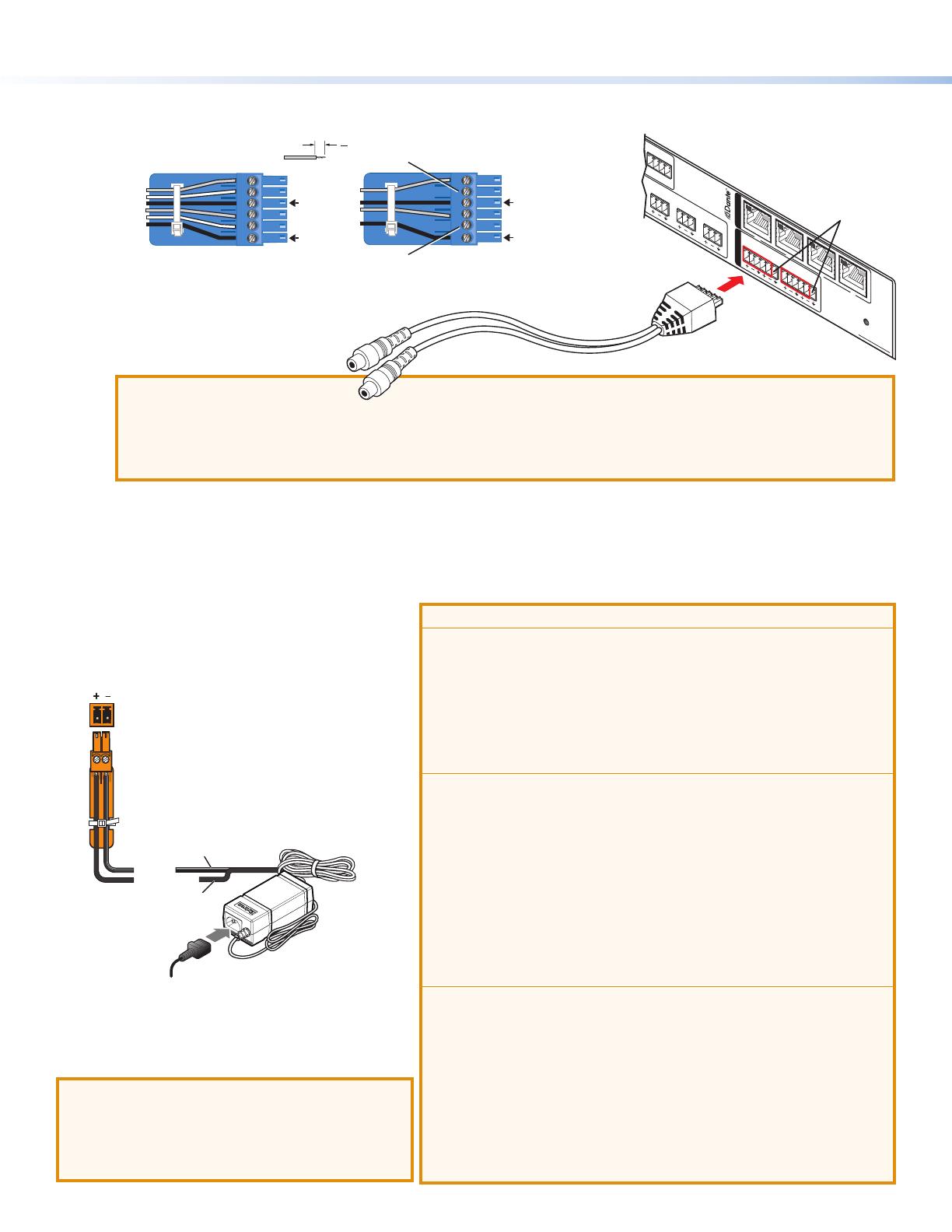
Analog audio output connectors 1 through 4 — Connect up to four balanced or unbalanced mono line level or two
stereo outputs to these 6-pole 3.5 mm captive screw audio output connectors. Wire as shown below.
Do not tin the wires!
(5 mm) MAX.
3 "
16
Balanced Output
Unbalanced Output
+
+
Tip
Ring
Tip
Ring
Slee
ves
Tip
No Ground Here
No Ground Here
Tip
Sleeves
Slee
ves
Sleeves
+
+
Alternatively, 3-pole or 5-pole
connectors can be used (see the
5-pole wiring example at right).
ATTENTION:
For unbalanced audio outputs, connect the sleeves to the ground contact. DO NOT connect the sleeves to the
negative (-) contacts.
Pour l’audio asymétrique, connectez les manchons au contact au sol. Ne PAS connecter les manchons aux
contacts négatifs (–).
E
AT port connectors — This four-port Gigabit switch with four RJ-45 Ethernet connectors supports digital audio
transport (AT) and communications. Connect one or more ports to a LAN using standard CAT cable. Connect one or more
AXP64CATs to an audio mixing processor such as a DMP128AT to form a larger matrix system (see Creating a Physical
Dante Network on page8). Up to 56 channels can be connected.
F
Reset button — Pressing this recessed button returns the AXP64 C AT to its factory default state (see “Resetting” in the
AXP64CAT User Guide).
ATTENTION:
Always use a power supply provided by or specied by Extron.
Use of an unauthorized power supply voids all regulatory
compliance certication and may cause damage to the supply
and the end product.
Utilisez toujours une source d’alimentation fournie par Extron.
L’utilisation d’une source d’alimentation non autorisée annule
toute conformité réglementaire et peut endommager la source
d’alimentation ainsi que l’unité.
Unless otherwise stated, the AC/DC adapters are not suitable for
use in air handling spaces or in wall cavities. The power supply is
to be located within the same vicinity as the Extron AV processing
equipment in an ordinary location, Pollution Degree2, secured to
the equipment rack within the dedicated closet, podium, or desk.
Sauf mention contraire, les adaptateurs AC/DC ne sont pas
appropriés pour une utilisation dans les espaces d’aération ou
dans les cavités murales. La source d’alimentation doit être
située à proximité de l’équipement de traitement audiovisuel
dans un endroit ordinaire, avec un degré2 de pollution, fixé à un
équipement de rack à l’intérieur d’un placard, d’une estrade, ou
d’un bureau.
The installation must always be in accordance with the applicable
provisions of National Electrical Code ANSI/NFPA 70, article 725
and the Canadian Electrical Code part 1, section 16. The power
supply shall not be permanently xed to building structure or
similar structure.
Cette installation doit toujours être en accord avec les mesures
qui s’applique au National Electrical Code ANSI/NFPA70,
article725, et au Canadian Electrical Code, partie1, section16.
La source d’alimentation ne devra pas être fixée de façon
permanente à une structure de bâtiment ou à une structure
similaire.
Connecting Power
Wire the 12 VDC power supply as shown in gure 2.
Rear Panel
Power Receptacle
DC Power Cord
Captive Screw
Connector
Ground
all devices.
External
Power Supply
12 VDC, 1 A max.
Extr
on Part Number 70-775-01 (28-071-57LF)
– Return
+12 VDC input
Ridged
Smooth
1A MAX
100-240V 50-60Hz
Figure 2. External Power Supply Connection
With all connections made, power up the input
devices, then apply power to the AXP64CAT.
ATTENTION:
Do not connect power to the AXP until you
have read the Attention notices at right.
Ne branchez pas l’alimentation au AXP avant
d’avoir lu les mises en garde Attention a droit.
DO NOT
Connect Here
AXP 64 C AT
RESET
1
1
1
IN G
POWER
12V
X.XA MAX
01 02
2 3 4
I/O
INPUTS
OUTPUTS
AT
2
IN G 01 02
3
IN G 01 02
4
IN G 01 02
2
3
4
5
6
1
2
3
4
5-pole CSR
3
Product Category
Front Panel Indicators
AXP 64 C AT
INPUTS OUTPUTS
1
CLIP
SIGNAL
AUDIO EXPANSION PROCESSOR
Extron
2 3 4 1 2 3 45 6
CLIP
SIGNAL
Figure 3. AXP64CAT Front Panel
A
Power LED This green LED blinks during boot-up and lights steadily when the AXP64CAT is powered on and ready to
operate.
B
Input LEDs One pair for each of the six inputs:
Clip indicators — These red LEDs light when the corresponding input signal exceeds -3 dBFS. The clip indicator
remains on for 200ms after the input signal drops below that level.
Signal indicators — These green LEDs light when there is an active source on the corresponding input.
C
Output LEDs — One pair for each of the four analog outputs:
Clip indicators — These red LEDs light when the corresponding output signal exceeds -3 dBFS. The clip indicator
remains on for 200ms after the output signal drops below that level.
Signal indicators — These green LEDs light when a signal is detected on the corresponding output.
Connecting the AXP 64 C AT to a Network
The AXP 64 supports 100 and 1000 Mbps halfduplex and full duplex connections. You can use either a straight-through Ethernet
cable or a crossover cable to connect the AXP to a network via any one of the four AT ports (see figure 1,
E
, on page 1). The
control device must be connected to the same network. If you do not know the IP address of the AXP 64, use Dante Controller
to obtain it (see Finding a Dante Device Address on page 6). When all connections are made and power is applied, the green
(activity) LED of the connected AT port blinks to indicate data activity on the connection.
Downloading and Installing Dante Controller and DSP Configurator Software
There are no hardware controls for
the AXP64CAT. Dante Controller
from Audinate
®
is required to select
and route digital inputs and outputs
to connected Dante-compatible
devices. DSP Congurator is used for
conguration.
Install DSP Congurator and Dante
Controller on a PC running Microsoft
®
Windows
®
7 or newer. For full details
about computer requirements, see
the product page on the Extron
website. Dante Controller must be
installed to rename the connected
AXP64CAT to assist identication
on the network.
Both software applications are
available at www.extron.com.
1. On the Extron Electronics web
page, click the Download tab.
The Download screen opens.
2. On Download screen, click the
Dante Controller link (
1
) on the left sidebar.
4
AXP64CAT • Setup Guide (Continued)
3. On the Dante Controller web page, click Download (
1
).
4. On the Download Center page, follow the prompts to download the Dante Controller installer le.
5. If the Download Center page has closed, click the Download tab again to access the left sidebar.
6. On the left sidebar, click DSP Congurator Software.
7. On the DSP Congurator web page, click the Download button. The Download Center page is displayed again.
8. Follow the prompts to download DSP Congurator.
9. If you have saved either or both software les, install them when ready.
By default, the installed Dante Controller program les are saved in C:\Program Files (x86)\Audinate\Dante
Controller\DanteController.exe.
By default, the DSP Congurator les are installed in C:\Program Files (x86)\Extron\DSP Congurator.
NOTE: On the first installation of DSP Configurator, a USB driver automatically loads. Follow the on-screen instructions. After
the USB driver loads, installation continues.
5
Product Category
Setting Up the Dante Network
Communication between the AXP64CAT and a controlling device or a computer running software such as Extron DataViewer is
performed via a TCP socket using port 4333. Use a standard Ethernet cable to connect the AXP to a network via one of the four
RJ-45 AT ports (see figure 1,
E
, on page 1).
Renaming an AXP64CAT
Dante Controller auto-discovers all Dante devices on the network and advertises itself to allow other Dante-enabled devices to
communicate with it.
NOTE: The default device name is the model number followed by the last six digits of the MAC address of the device (located
on a sticker on the rear panel).
Multiple devices on the same network can present difculty
identifying inputs and outputs. To avoid confusion, rename
each device to a unique identier.
NOTE: To simplify renaming, connect only one Dante
device to the network at a time. As each device is
renamed, it can remain connected.
1. Ensure that the control computer and a single unnamed
AXP64CAT are connected to the same network.
2. Open the Dante Controller software on your computer.
The Dante Controller - Network View screen is
displayed. All Dante devices on the network are discovered
and listed.
3. From the Device menu, select Device View.
4. The Dante Controller - Device View dialog
opens. Select your device from the (Select a Dante
Device...) drop-down list.
NOTE: If there are multiple AXP64s connected to the network that have not been renamed, to identify an individual
device you must obtain the media access code (MAC) address of the desired device from the label on the rear panel.
The Device View dialog populates with the selected AXP64CAT information.
6
AXP64CAT • Setup Guide (Continued)
5. Click the Device Cong tab (
1
) to open the device conguration page.
6. In the Rename Device panel, enter the new name of the device in the text eld. No spaces are allowed in the name.
7. Click Apply. A conrmation prompt opens.
8. Click Yes to enter the new name, then close the Device Conguration dialog box.
The new name is written to the AXP64CAT. Repeat as necessary for all AXP64CAT devices.
NOTE: After the AXP64CAT is renamed, it can remain connected to the network. However, subsequent devices must be
connected one at a time and renamed before the next device is connected.
Finding a Dante Device IP Address
To nd the IP address of a Dante device, you need the name of the device (see Renaming an AXP64CAT on the previous
page).
NOTE: If the AXP 64 has not been renamed, its default name consists of the product name followed by a hyphen (AXP64-)
plus the last 6 digits of the unit MAC address (for example, AXP64-040C06).
1. Open Dante Controller for Windows (see Renaming an AXP 64 C AT).
2. On the Dante Controller main screen, click the Device Info tab (
1
).
3. On the Device Info screen, locate the name of your AXP. The IP address is in the Primary Address column (
1
).
4. Connect the AXP to a computer (using a host communication utility such as Extron DataViewer) or to a control system.
5. Select a TCP/IP connection and enter the IP address of the AXP 64 where indicated. Enter 4333 for the port number.
7
Product Category
Configuring the AXP64CAT
After the device is named, use the DSP Congurator to congure the AXP64CAT as desired.
1. Ensure the control computer and AXP64CAT are connected to the same network and that the AXP64CAT is renamed for
identication (see Renaming an AXP64CAT on page5).
2. Start the DSPCongurator software. From the drop-down list on the opening page, select AXP64CAT and press OK.
The main screen opens. The main screen provides access to all the features of the AXP64CAT. Full details about using the
software are found in the AXP64CAT User Guide on the Extron website or in the DSP Congurator help les.
3. The program starts in Emulate mode. Select the appropriate operating mode as follows:
To create a conguration ofine to upload (push) to the AXP64CAT at a
later time, keep the AXP in emulate mode.
To push a conguration to the AXP, pull a conguration from the device, or to
make immediate changes to the conguration or operation, click the Live
button to place the AXP in Live mode.
NOTE: Changing from emulate to live mode opens the Connect to
device... dialog box (shown at right). Select the device in the
Dante Devices panel.
On the next dialog box that appears, select the appropriate radio
button to pull data from the selected device to update your
conguration, or to push data from the current conguration to the
selected device, overwriting any existing data.
8
AXP64CAT • Setup Guide (Continued)
Loading Building Blocks
The discrete signal paths can be individually loaded with pre-congured, modular templates called building blocks. These blocks
are designed for specic microphones, source devices, analog and digital inputs, and can streamline initial conguration. The
building blocks contain conguration parameters tailored to a selected input device.
Loading a building block congures each block in the signal path with pre-determined parameters to match the selected device
characteristics. Although tailored for the specic device, the processing blocks can still be customized, if necessary.
To load a building block:
1. Click the input number. The Building Blocks dialog opens.
2. Choose a building block that best describes the connected input device. As the pointer moves over the selection, the text is
underlined. Click the selection to load the block.
The building block loads pre-congured processor and gain block parameters. Processor blocks are initially bypassed.
3. If necessary, further customize the processor blocks according to the requirements of the system (see the AXP64CAT User
Guide on the Extron website).
Creating a Physical Dante Network
A physical network is required to share Dante audio channels between AXP64CAT and devices such as the DMP128 AT. The
AXP64CAT and the DMP128AT each have a four-port switch with four RJ-45 connectors located on the back panel that accept
standard network cables. A DMP128-based Dante network can be congured in a daisy-chain or star network topology using the
four-port switch and the Dante Controller in switched mode.
Star Network
Star network topology places one DMP128AT as the central unit, which connects directly to up to three AXP units (see gure 4).
Alternatively, a larger network switch in place of the central DMP128AT allows more than four AXP64CATs to connect in the
star conguration.
100-240V ~ --A MAX
50/60 Hz
LAN
EXP
RS-232
Tx Rx G
RESET
MIC +48V
5678
1234
8
4 1
1 2345G6
1234
78910 G
11 12 13 14 15 G1617181920G
234
56 78
910
11 127
3
6
2
5
1
MIC/LINE INPUT
S
OUTPUTS
DIGITAL I/O
REMOTE AT
DMP 128 C AT
AXP 64 C AT
AXP 64 C AT
RESET
1
1
1
IN G
POWER
12V
X.XA MAX
01 02
234
I/OINPUTS
OUTPUTS
AT
2
IN G0102
3
IN G0102
4
IN G0102
2 3 4 5 6 1 2 3 4
AXP 64 C AT
AXP 64 C AT
RESET
1
1
1
IN G
POWER
12V
X.XA MAX
01 02
234
I/OINPUTS
OUTPUTS
AT
2
IN G0102
3
IN G0102
4
IN G0102
2 3 4 5 6 1 2 3 4
DMP 128 C AT
AXP 64 C AT
AXP 64 C AT
RESET
1
1
1
IN G
POWER
12V
X.XA MAX
01 02
234
I/OINPUTS
OUTPUTS
AT
2
IN G0102
3
IN G0102
4
IN G0102
2 3 4 5 6 1 2 3 4
Figure 4. Star Network Topology
9
Product Category
Daisy Chain Configuration
A daisy chain conguration can also be used. Each unit is connected to both the previous unit and the next unit in the chain.
DMP 128 AT
100-240V ~ --A MAX
50/60 Hz
LAN
EXP
RS-232
Tx Rx G
RESET
MIC +48V
5678
1234
8
4 1
1 2345G6
1234
78910G
11 12 13 14 15 G1617181920G
234
56 78
910
11 127
3
6
2
5
1
MIC/LINE INPUTS
OUTPUTS
DIGITAL I/O
REMOTE AT
DMP 128 C AT
AXP 64 C AT #1
AXP 64 C AT #2
AXP 64 C AT #3
AXP 64 C AT
RESET
1
1
1
IN G
POWER
12V
X.XA MAX
01 02
234
I/OINPUTS
OUTPUTS
AT
2
IN G0102
3
IN G0102
4
IN G0102
2 3 4 5 6 1 2 3 4
AXP 64 C AT
RESET
1
1
1
IN G
POWER
12V
X.XA MAX
01 02
234
I/OINPUTS
OUTPUTS
AT
2
IN G0102
3
IN G0102
4
IN G0102
2 3 4 5 6 1 2 3 4
AXP 64 C AT
RESET
1
1
1
IN G
POWER
12V
X.XA MAX
01 02
234
I/OINPUTS
OUTPUTS
AT
2
IN G0102
3
IN G0102
4
IN G0102
2 3 4 5 6 1 2 3 4
Figure 5. Daisy Chain Topology
Hybrid versions combining the star and daisy chain topologies can be built, but a ring topology, or any topology that creates a
duplicate connection causes a connection failure in Dante Controller.
NOTE: Connections between ports in either a star or daisy chain network do not need to be sequential (1 to 2, 2 to 3, 3 to 4),
nor do they need to be made between the same port numbers (1 to 1, 2 to 2, 3 to 3, 4 to 4).
Dante Operation
Selecting Devices
After the inputs of the AXP64CAT are congured, they must be routed to the other Dante devices on the audio network. To do
this, use Dante Controller.
1. Ensure the control computer and AXP64CAT are
connected to the same network.
2. From the start menu select:
All Programs > Audinate > Dante Controller >
Dante Controller.
The Dante Controller - Network View screen opens.
Dante Controller auto-discovers Dante devices on the
network and advertises itself to allow other Dante-enabled
devices to communicate with it. Device inputs are Dante
receivers (listed vertically on the left) and device outputs
are Dante transmitters (listed horizontally across the top).
Transmitters (outputs) connect to receivers (inputs) using
the connection matrix.
3. Click the + box next to any Dante device in the Dante
Receivers panel, (such as the DMP128 (
1
in the
example at right) to show all device inputs.
4. Click the + box next to the AXP64CAT (
2
) in the Dante
Transmitters panel to show all device outputs.
10
© 2017 Extron Electronics All rights reserved. All trademarks mentioned are the property of their respective owners. www.extron.com
68-2721-50 B
12 17
Routing Inputs and Outputs
1. Click the + box next to the input channels (receivers) on
another Dante device (DMP128-Rack01 DIGITAL_IN-01
in the example at right).
All device outputs (transmitters) display horizontally.
2. Click the junction of the desired connection (
1
).
Example: AXP64-Lab OUTPUT-01 to
DMP128-Rack01 DIGITAL_IN-01 (shown at right).
A check mark at the junction indicates the connection is
made. A check mark is also placed next to the receiver
channel.
NOTE: An input (receiver) can connect to only one
output (transmitter). An output (transmitter) can
connect to multiple inputs (receivers).
3. Click the junction again to disconnect the input from the
output.
Additional AXP64CAT outputs (Dante transmitters) can
be connected to or disconnected from other Dante device
inputs (Dante receivers) using the same method (see the
“Dante Controller” section of the AXP64 C AT User Guide for
information on Dante Controller operation).
  • Page 1 1
  • Page 2 2
  • Page 3 3
  • Page 4 4
  • Page 5 5
  • Page 6 6
  • Page 7 7
  • Page 8 8
  • Page 9 9
  • Page 10 10

Extron AXP 64 C AT User manual

Category
Serial switch boxes
Type
User manual

Extron AXP 64 C AT is a versatile audio expansion processor designed to enhance audio capabilities in various professional environments. With its digital and analog connectivity options, it provides flexible signal routing and processing for up to 56 channels of Dante audio. The device features six balanced/unbalanced microphone or mono line level inputs with 48-volt phantom power for the first four inputs. Four balanced/unbalanced mono line level or two stereo outputs offer versatile connectivity for audio distribution.

Ask a question and I''ll find the answer in the document

Finding information in a document is now easier with AI