Mettler Toledo (software version 1.x) transmitter module pH 2700i(X) Operating instructions
- Category
- Measuring, testing & control
- Type
- Operating instructions

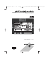
pH 2700i(X) module
Instruction manual
Order number: 52 121 276
69904_E_2700i.QXD 28.09.2005 15:01 Uhr Seite 1 gro DAISY.DATA01:NETDATA:MAC2ALL:BA:M700X_Version_6:pH2

TA-201.035-MTE01 011005 Software version 1.x
Registered trademarks
The following registered trademarks are used in this instruction manual
without further marking
Calimatic
Sensocheck
Sensoface
ServiceScope
VariPower
SMARTMEDIA
®
is a registered trademark of Toshiba Corp., Japan
InPro
®
is a registered trademark of Mettler-Toledo GmbH, Switzerland
Warranty
Defects occurring within 1 year from delivery date shall be remedied free of charge at our plant
(carriage and insurance paid by sender).
©2005 Subject to change without notice
Mettler-Toledo GmbH, Process Analytics, Industrie Nord,
CH-8902 Urdorf, Tel. +41 (44) 736 22 11 Fax +41 (44) 736 26 36
Subject to technical changes. Mettler-Toledo GmbH, 09/05.
Printed in Germany.
Return of products under warranty
Please contact your local Mettler-Toledo representative before returning a defective device. Ship the
cleaned device to the address you have been given. If the device has been in contact with process fluids,
it must be decontaminated/disinfected before shipment. In that case, please attach a corresponding
certificate, for the health and safety of our service personnel.
Disposal
Please observe the applicable local or national regulations concerning the disposal of “waste electrical
and electronic equipment”.
69904_E_2700i.QXD 28.09.2005 15:01 Uhr Seite 2 gro DAISY.DATA01:NETDATA:MAC2ALL:BA:M700X_Version_6:pH2

69904_E_2700i.QXD 28.09.2005 15:01 Uhr Seite 3 gro DAISY.DATA01:NETDATA:MAC2ALL:BA:M700X_Version_6:pH2

Warranty ......................................................................................................2
Registered trademarks..................................................................................2
EC Declaration of Conformity ......................................................................3
Intended use ................................................................................................8
Safety information........................................................................................9
Software version .......................................................................................10
Modular concept and instruction manuals ...........................................11
Short description: M 700 FRONT ................................................................12
Short description: Menu structure ..............................................................13
Short description: M 700 BASE...................................................................15
Parameter tables (Excel) at www.mtpro.com...............................................17
ISM - Intelligent Sensor Management...................................................18
ISM - Plug and Measure...........................................................................19
ISM - First Calibration ..............................................................................20
ISM - Parameter setting ...........................................................................21
ISM - Predictive maintenance...................................................................22
ISM - Diagnostics.....................................................................................23
Setting ISM diagnostics messages as favorite ...........................................24
Terminal plate ..........................................................................................27
Inserting the module ..................................................................................28
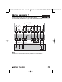
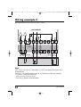
Wiring examples
ISM pH/ORP measurement with glass electrode .......................................29
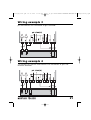
ISM pH measurement with ISFET sensor ..................................................30
pH measurement with Sensocheck of glass electrode ..............................31
Simultaneous pH and ORP measurement.................................................31
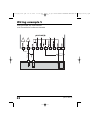
ORP measurement with Sensocheck for reference electrode ....................32
Quick start:
Menu selection, menu structure .................................................................34
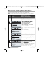
Passcode entry............................................................................................35
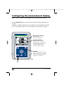
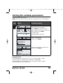
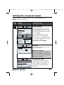
Configuring the measurement display ........................................................36
Contents
4
pH 2700i(X)
69904_E_2700i.QXD 28.09.2005 15:01 Uhr Seite 4 gro DAISY.DATA01:NETDATA:MAC2ALL:BA:M700X_Version_6:pH2

5
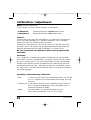
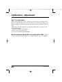
Calibration / adjustment ........................................................................38
Adjustment ................................................................................................39
Calibration methods ................................................................................40
Temperature compensation......................................................................41
Select calibration method ........................................................................42
Calimatic automatic buffer recognition....................................................44
Calibration with manual entry of buffer values .......................................46
Product calibration (calibration with sampling) ........................................48
Data entry of premeasured electrodes .....................................................50
Monitoring functions for calibration ........................................................51
ORP adjustment ......................................................................................52
Temperature dependence of commonly used reference systems ..............53
ISFET zero adjustment .............................................................................54
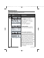
Maintenance ............................................................................................56
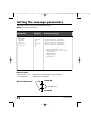
Setting the module parameters
Operating levels.......................................................................................57
Enable / lock functions.............................................................................58
Setting the module parameters................................................................59
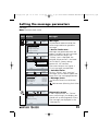
Setting the sensor data parameters .........................................................60
Sensoface ................................................................................................61
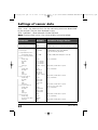
Settings of sensor data ............................................................................62
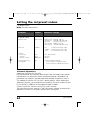
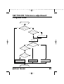
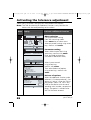
Tolerance adjustment: Program flow .......................................................65
Activating the tolerance adjustment (SW 700-005)..................................66
TC process medium .................................................................................68
ORP/rH value ...........................................................................................71
Delta function..........................................................................................71
Messages.................................................................................................73
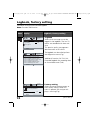
Setting the logbook parameters (System control)
Logbook ..................................................................................................74
Factory setting .........................................................................................74
Contents
69904_E_2700i.QXD 28.09.2005 15:01 Uhr Seite 5 gro DAISY.DATA01:NETDATA:MAC2ALL:BA:M700X_Version_6:pH2

6
pH 2700i(X)
Contents
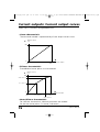
Setting the system control and the outputs (BASE)
Setting the current output .......................................................................75
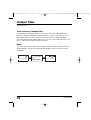
Output filter (time constant) ....................................................................78
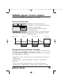
NAMUR signals (current outputs) - Behavior during messages - ...............79
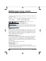
NAMUR signals (relay contacts):
failure, maintenance request, function check...........................................80
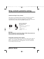
Relay contacts: protective wiring..............................................................81
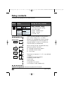
Setting the relay contacts ........................................................................82
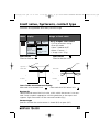
Limit value, hysteresis, contact type .........................................................83
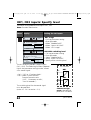
Setting the OK1, OK2 inputs (BASE)
Optocoupler inputs (BASE): Usage and switching level.............................84
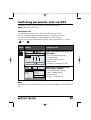
Switching parameter sets via OK2 (system control) ..................................85
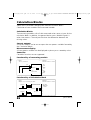
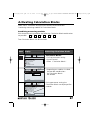
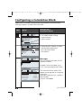
Calculation Blocks (System control)
Calculation of new variables from measured variables .............................86
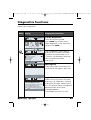
Diagnostics functions ..............................................................................89
Device description....................................................................................90
FRONT module ........................................................................................90
BASE module...........................................................................................90
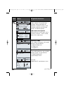
Module diagnostics..................................................................................91
Sensor monitor ........................................................................................91
ServiceScope (SW 700-004) .....................................................................91
Cal timer .................................................................................................92
Adaptive cal timer ...................................................................................92
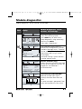
Tolerance band recorder (SW 700-005)....................................................92
Cal record................................................................................................93
Sensor network diagram..........................................................................93
Statistics ..................................................................................................93
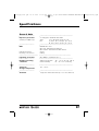
Specifications ...........................................................................................94
69904_E_2700i.QXD 28.09.2005 15:01 Uhr Seite 6 gro DAISY.DATA01:NETDATA:MAC2ALL:BA:M700X_Version_6:pH2

7
Contents
Appendix:
Minimum measuring spans for current outputs ..........................................98
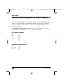
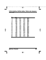
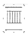
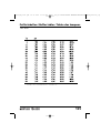
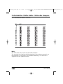
Buffer tables...............................................................................................99
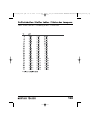
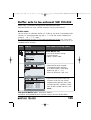
Buffer set to be entered (SW 700-002).....................................................105
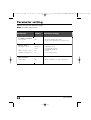
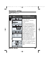
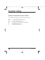
Overview of parameter setting............................................................106
Index.......................................................................................................111
Overview of icons .................................................................................115
Overview of menu selection ................................................................116
69904_E_2700i.QXD 28.09.2005 15:01 Uhr Seite 7 gro DAISY.DATA01:NETDATA:MAC2ALL:BA:M700X_Version_6:pH2

8
pH 2700i(X)
Intended use
The module is used for simultaneous pH, ORP, and temperature measurement
with glass electrodes, ISFET sensors, or sensors with ISM technology (Intelligent
Sensor Management). The use of ISFET sensors is an additional function which
can be enabled by a separately orderable TAN.
The pH 2700iX module is intended for operation in locations subject to
explosion hazards which require equipment of Group II, device category 2(1),
gas/dust.
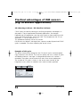
Conformity with FDA 21 CFR Part 11
In their directive “Title 21 Code of Federal Regulations, 21 CFR Part 11,
Electronic Records; Electronic Signatures” the US American health agency
FDA (Food and Drug Administration) regulates the production and processing
of electronic documents for pharmaceutical development and production.
This results in requirements for measuring devices used for corresponding
applications. The following features ensure that the M 700(X) modular
process analysis system meets the demands of FDA 21 CFR Part 11:
Electronic Signature
Access to the device functions is regulated and limited by individually
adjustable codes – “Passcodes”. This prevents unauthorized modification of
device settings or manipulation of the measurement results. Appropriate use
of these passcodes makes them suitable as electronic signature.
Audit Trail Log
Every change of device settings can be automatically recorded and docu-
mented in the Audit Trail Log on the SmartMedia card. The recording can be
encoded.
69904_E_2700i.QXD 28.09.2005 15:01 Uhr Seite 8 gro DAISY.DATA01:NETDATA:MAC2ALL:BA:M700X_Version_6:pH2

9
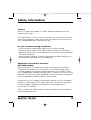
Safety information
Caution!
Never try to open the module! If a repair should be required, return the
module to our factory.
If the specifications in the instruction manual are not sufficient for assessing
the safety of operation, please contact the manufacturer to make sure that
your intended application is possible and safe.
Be sure to observe during installation:
• Switch off power supply before replacing or inserting a module.
•Protect the signal inputs of the modules against electrostatic discharge.
• Before commissioning it must be proved that the device may be connected
with other equipment.
• Observe correct shielding: To avoid interferences, the cable shielding must
be completely covered by the ESD shielding cap.
Application in hazardous locations:
pH 2700iX module
When using the M 700 module pH 2700iX, the stipulations for electrical
installations in hazardous areas (EN 60079-14) must be observed. When
installing the device outside the range of applicability of the 94/9/EC direc-
tive, the appropriate standards and regulations in the country of use must be
observed. The module has been developed and manufactured in compliance
with the applicable European guidelines and standards.
Compliance with the European Harmonized Standards for use in hazardous
locations is confirmed by the EC-Type-Examination Certificate. Compliance
with the European guidelines and standards is confirmed by the EC
Declaration of Conformity.
There is no particular direct hazard caused by the operation of the device in
the specified environment.
69904_E_2700i.QXD 28.09.2005 15:01 Uhr Seite 9 gro DAISY.DATA01:NETDATA:MAC2ALL:BA:M700X_Version_6:pH2

10
pH 2700i(X)
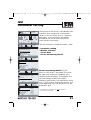
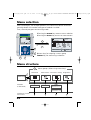
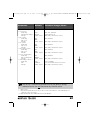
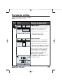
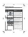
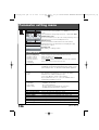
Menu Display Device description
Provides information about all mod-
ules installed: Module type and func-
tion, serial number, hardware and
software version and device options.
Select the different modules (FRONT,
BASE, slots 1 - 3) using the arrow
keys.
Device description
Return
22.7 °C
7.00 pH
M 700 operating panel
Module FRONT 700X-015
Hardware: 2, Software: 6.2
Serial number: 0000815
BASE
Module
FRONT
Software version
pH 2700i(X) module
Device software M 700(X)
The pH 2700i module is supported by software version 6.2 or higher.
The pH 2700iX module is supported by software version 6.2 or higher.
Module software pH 2700i(X)
Software version 1.0 xx.xx.2005 pH module with ISM functionality.
Query actual device/module software
When the analyzer is in measuring mode:
Press menu key, open Diagnostics menu.
Options
69904_E_2700i.QXD 28.09.2005 15:01 Uhr Seite 10 gro DAISY.DATA01:NETDATA:MAC2ALL:BA:M700X_Version_6:pH

11
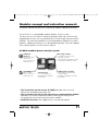
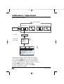
Modular concept and instruction manuals
Instruction manuals for basic unit, measuring module, additional functions.
• The instruction manual for the M 700(X) describes how to install,
commission and operate the basic unit.
• The instruction manual for the measuring or communication module
describes all functions required for commissioning and working with
the respective measuring or communication module.
• Additional functions are supplied with a function description.
The M 700(X) is an expandable modular process analysis system.
The basic unit (M 700 FRONT and BASE) provides three slots which can be
equipped by the user with any combination of measuring or communication
modules. The software capabilities can be expanded by additional functions
(options). Additional functions must be ordered separately. They are supplied
with a device-specific TAN for function release.
3 module slots
for free combination of
measuring and communica-
tion modules
Measuring modules
• pH / ORP / Temp (also ISM)
•0
2
/Temp (also ISM)
• Noncontacting conductivity / Temp
• Contacting conductivity / Temp
Additional
functions
Activation via device-
specific TAN
For an overview, see
www.mtpro.com
SmartMedia card
Data recording
For an overview, see
www.mtpro.com.
M 700(X) modular process analysis system
Communication modules
• Out (additional switching and
current outputs)
• PID (analog and digital controller)
•Profibus PA
r
e
t
r
o
f
it
a
b
l
e
O
p
t
i
o
n
69904_E_2700i.QXD 28.09.2005 15:01 Uhr Seite 11 gro DAISY.DATA01:NETDATA:MAC2ALL:BA:M700X_Version_6:pH

pH 2700i(X)
12
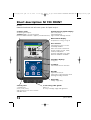
Short description: M 700 FRONT
M 700
Modular hardware and software system for liquid analysis.
Transflective LC graphic display
(240 x 160 pixels)
white backlighting,
high resolution and high contrast.
Red LED
signals failure (On) or
maintenance request/function check
(flashing) according to NE 44.
4 captive scews
for opening the analyzer
(Caution! Make sure that the gasket
between FRONT and BASE is properly seated and clean!)
Green LED
Voltage supply okay
5 self-sealing cable glands
M20 x 1.5
for entry of voltage supply and signal lines
2 softkeys
with context-sensitive functions.
User interface
with plaintext menus as recom-
mended by NAMUR.
Menu texts can be switched to:
German, English, French, Italian,
Swedish, and Spanish.
Intuitively acquirable menu logic,
based on Windows standards.
Control panel
3 function keys
(menu, meas, enter)
and 4 arrow keys for menu selection
and data entries
Measurement display
For parameter setting, see Pg 36
Secondary displays
see Pg 24
69904_E_2700i.QXD 28.09.2005 15:01 Uhr Seite 12 gro DAISY.DATA01:NETDATA:MAC2ALL:BA:M700X_Version_6:pH

13
Measuring
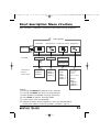
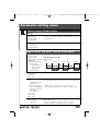
Short description: Menu structure
Basic functions: Calibration, maintenance, parameter setting, diagnostics
Calibration Maintenance Parameter setting Diagnostics
Menu groups
1
2
3
1147
2958
1246
Operator level
1989
Administrator level
Passcode:
Selection of
further
menu items:
Module 1
Module 2
Module 3
BASE
Module 1
Module 2
Module 3
SYSTEM
FRONT
BASE
Module 1
Module 2
Module 3
4
5
Legend:
(1) Pressing the menu key accesses menu selection
(2) Pressing the meas key returns to measurement
(3) Menu groups are selected using the arrow keys
(4) Press enter to confirm, enter passcode
(5) Further menu items are displayed
(6) Selected functions of the Diagnostics menu can be recalled via
softkey even when in measuring mode (“Favorites”, Pg 24)
Message list
Point of meas
description
Logbook
Device description
FRONT
BASE
Module 1
Module 2
Module 3
69904_E_2700i.QXD 28.09.2005 15:01 Uhr Seite 13 gro DAISY.DATA01:NETDATA:MAC2ALL:BA:M700X_Version_6:pH

04
pH 2700i(X)
14
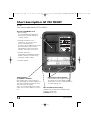
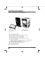
Short description: M 700 FRONT
M 700
View into the open device (M 700 FRONT)
Terminal plates
of “hidden” modules
Each module comes with an adhesive
label containing the contact assignments.
This label should be sticked to the inner
side of the front (as shown).
Then, the terminal assignments remain
visible even if further modules are insert-
ed.
Slot for SmartMedia card
• Data recording
The SmartMedia card expands the
measurement recorder capacity to
> 50000 records.
• Exchange of parameter sets
5 parameter sets can be stored
on the SmartMedia card,
2 of them can be loaded to the M 700
and switched by remote control.
Configurations can be transferred
from one transmitter to the other.
• Function expansions
are possible with additional software
modules which are released using
transaction numbers (TAN).
• Software updates
The circumferential sealing
guarantees IP 65 protection and allows spray
cleaning / disinfection.
Caution! Keep clean!
Replacing the front module
Pull off power cord and ground wire.
To separate the M 700 FRONT from the
M 700 BASE, turn the retaining screws of
the pivot hinge by 90°.
69904_E_2700i.QXD 28.09.2005 15:01 Uhr Seite 14 gro DAISY.DATA01:NETDATA:MAC2ALL:BA:M700X_Version_6:pH

15
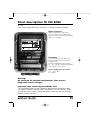
Short description: M 700 BASE
M 700
View into the open device (M 700 BASE, 3 function modules installed)
M 700 BASE
2 current outputs (free assignment of
process variable) and 4 relay contacts,
2 digital inputs.
VariPower broad-range power supply,
20 ... 265 V AC/DC, suitable for all public
mains supplies in the world.
Power supply units, IS version:
100 ... 230 V AC or
24 V AC/DC
Important note concerning SmartMedia card
The SmartMedia card may be inserted or replaced with the power supply
switched on. Before a memory card is removed, it must be “closed” in the
maintenance menu. When closing the device, make sure that the sealing is
properly seated and clean.
Module equipment
Module identification: Plug & Play
Up to 3 modules can be combined as
desired. Several input and communication
modules are available.
Warning!
Do not touch the terminal compartment, there may be
dangerous contact voltages!
69904_E_2700i.QXD 28.09.2005 15:01 Uhr Seite 15 gro DAISY.DATA01:NETDATA:MAC2ALL:BA:M700X_Version_6:pH

16
pH 2700i(X)
69904_E_2700i.QXD 28.09.2005 15:01 Uhr Seite 16 gro DAISY.DATA01:NETDATA:MAC2ALL:BA:M700X_Version_6:pH

17
Parameter tables (Excel):
www.mtpro.com
Parameter tables (Excel)
2 complete parameter sets can be stored in the basic device M 700(X). You
can document the parameter settings of your complete measuring point in
an Excel table that can be downloaded from our website.
The complete documentation is available in the download area of our
website www.mtpro.com.
69904_E_2700i.QXD 28.09.2005 15:01 Uhr Seite 17 gro DAISY.DATA01:NETDATA:MAC2ALL:BA:M700X_Version_6:pH

18
pH 2700i(X)
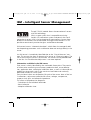
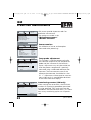
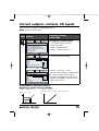
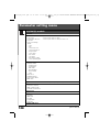
ISM – Intelligent Sensor Management
The pH 2700i(X) module allows the connection of sensors
with ISM technology.
ISM is an open system that is compatible to existing
VarioPin (VP) connection systems and permits the use of
conventional sensors. ISM is not restricted to pH measurement. Sensors from
different manufacturers can be connected. During pH measurement it is still
possible to continuously monitor the glass and reference electrode.
ISM sensors have an “electronic datasheet” which allows the storage of addi-
tional operating parameters such as calibration date and settings directly in the
sensor.
An ISM sensor is immediately identified due to the “Plug & Measure” con-
cept. This ensures the clear assignment of a sensor to a measuring point. The
risk of confusing the sensors is eliminated. The sensors can be precalibrated
in the lab. On-site calibration/adjustment is no more required.
Information available in the ISM sensor
Each sensor is clearly identified by the unalterable factory data. They consist
of information concerning manufacturer, production date, sensor descrip-
tion, application data, and original calibration data, as well as information on
predictive maintenance, such as the maximum load index and maximally
permitted number of CIP/SIP cycles.
Statistical data inform on the product life cycle of the sensor: data of the last
3 calibrations, adjustment record, buffer values, voltages, temperature,
response time, glass and reference impedance.
This allows a comprehensive diagnostic:
- Calculation of the individual load index
- Wear indication
- Adaptive calibration timer
69904_E_2700i.QXD 28.09.2005 15:01 Uhr Seite 18 gro DAISY.DATA01:NETDATA:MAC2ALL:BA:M700X_Version_6:pH

19
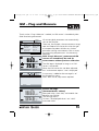
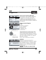
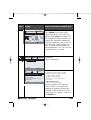
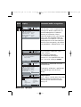
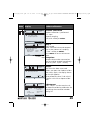
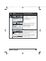
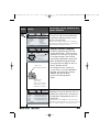
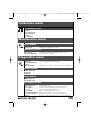
ISM – Plug and Measure
Thanks to the “Plug & Measure” method, an ISM sensor is immediately iden-
tified after being connected:
ISM sensor connected
25.6 °C
Proceed
Manufacturer:
Article No.:
6.53 pH
Adjustment:
Serial number:
Sensor:
Mettler-Toledo
52002559
09.05.05 08:15
0000313
InPro 3250SG
All sensor-typical parameters are automatically
sent to the analyzer.
These are, for example, the measurement range,
zero and slope of the sensor, but also the type
of temperature probe. Without any further
parameter setting, measurement starts at once,
the measuring temperature is simultaneously
detected.
With “Plug & Measure”, premeasured ISM
sensors can immediately be used for
measurement without previous calibration.
6.53
25.6
pH
°C
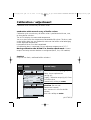
Date 09/06/05
Parameter set
The ISM logo is displayed as long as an ISM
sensor is connected.
When the ISM sensor has not been adjusted,
the “maintenance request” icon is displayed.
Failure message
(incorrect meas. values)
Measured value, alarm icon, and module slot
identifier are flashing.
The flashing means:
Caution! The displayed value is no “valid”
measured value!
A new entry is added to the message list of
the Diagnostics menu:
Warn New sensor, adjustment required
Message list 1 messg.
Return
Warn New sensor, adjustment required
25.6 °C
6.53 pH
16.53
125.6
pH
°C
Date 09/06/05
Parameter set
69904_E_2700i.QXD 28.09.2005 15:01 Uhr Seite 19 gro DAISY.DATA01:NETDATA:MAC2ALL:BA:M700X_Version_6:pH

20
pH 2700i(X)
ISM
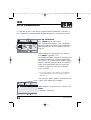
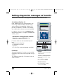
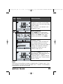
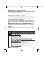
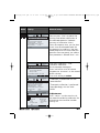
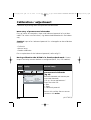
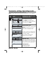
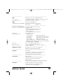
First Calibration
It is possible to use a new sensor without previous calibration. However, a
FIrst Calibration is recommended to achieve optimum measurement results.
Call up calibration
Press menu key to select menu.
The “maintenance request” and “calibration”
icons are flashing to indicate that calibration is
recommended. An entry is made in the mes-
sage list.
Menu selection
Return to meas
6.53 pH
25.6 °C
Select:
[enter]
Lingua
Select calibration using arrow keys, confirm
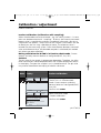
with enter. Passcode: 1147.
(To change passcode: Parameter setting/System
control/Passcode entry) After passcode entry,
the system is in function check mode: Current
outputs and relay contacts behave as config-
ured* and supply either the last measured
value or a fixed value until the Calibration
menu is exited.
* The current outputs / relay contacts are configured
in the M 700 BASE or the communication modules
(Out, PID).
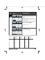
Calibration
Return
Info
Module pH 2700i
6.53 pH
25.6 °C
The“function check” mode is indicated by the
“Hold” icon (upper left of display).
Select module using arrow keys, confirm with
enter.
Calibration: See Pg 42.
69904_E_2700i.QXD 28.09.2005 15:01 Uhr Seite 20 gro DAISY.DATA01:NETDATA:MAC2ALL:BA:M700X_Version_6:pH
Page is loading ...
Page is loading ...
Page is loading ...
Page is loading ...
Page is loading ...
Page is loading ...
Page is loading ...
Page is loading ...
Page is loading ...
Page is loading ...
Page is loading ...
Page is loading ...
Page is loading ...
Page is loading ...
Page is loading ...
Page is loading ...
Page is loading ...
Page is loading ...
Page is loading ...
Page is loading ...
Page is loading ...
Page is loading ...
Page is loading ...
Page is loading ...
Page is loading ...
Page is loading ...
Page is loading ...
Page is loading ...
Page is loading ...
Page is loading ...
Page is loading ...
Page is loading ...
Page is loading ...
Page is loading ...
Page is loading ...
Page is loading ...
Page is loading ...
Page is loading ...
Page is loading ...
Page is loading ...
Page is loading ...
Page is loading ...
Page is loading ...
Page is loading ...
Page is loading ...
Page is loading ...
Page is loading ...
Page is loading ...
Page is loading ...
Page is loading ...
Page is loading ...
Page is loading ...
Page is loading ...
Page is loading ...
Page is loading ...
Page is loading ...
Page is loading ...
Page is loading ...
Page is loading ...
Page is loading ...
Page is loading ...
Page is loading ...
Page is loading ...
Page is loading ...
Page is loading ...
Page is loading ...
Page is loading ...
Page is loading ...
Page is loading ...
Page is loading ...
Page is loading ...
Page is loading ...
Page is loading ...
Page is loading ...
Page is loading ...
Page is loading ...
Page is loading ...
Page is loading ...
Page is loading ...
Page is loading ...
Page is loading ...
Page is loading ...
Page is loading ...
Page is loading ...
Page is loading ...
Page is loading ...
Page is loading ...
Page is loading ...
Page is loading ...
Page is loading ...
Page is loading ...
Page is loading ...
Page is loading ...
Page is loading ...
Page is loading ...
Page is loading ...
Page is loading ...
Page is loading ...
Page is loading ...
Page is loading ...
-
 1
1
-
 2
2
-
 3
3
-
 4
4
-
 5
5
-
 6
6
-
 7
7
-
 8
8
-
 9
9
-
 10
10
-
 11
11
-
 12
12
-
 13
13
-
 14
14
-
 15
15
-
 16
16
-
 17
17
-
 18
18
-
 19
19
-
 20
20
-
 21
21
-
 22
22
-
 23
23
-
 24
24
-
 25
25
-
 26
26
-
 27
27
-
 28
28
-
 29
29
-
 30
30
-
 31
31
-
 32
32
-
 33
33
-
 34
34
-
 35
35
-
 36
36
-
 37
37
-
 38
38
-
 39
39
-
 40
40
-
 41
41
-
 42
42
-
 43
43
-
 44
44
-
 45
45
-
 46
46
-
 47
47
-
 48
48
-
 49
49
-
 50
50
-
 51
51
-
 52
52
-
 53
53
-
 54
54
-
 55
55
-
 56
56
-
 57
57
-
 58
58
-
 59
59
-
 60
60
-
 61
61
-
 62
62
-
 63
63
-
 64
64
-
 65
65
-
 66
66
-
 67
67
-
 68
68
-
 69
69
-
 70
70
-
 71
71
-
 72
72
-
 73
73
-
 74
74
-
 75
75
-
 76
76
-
 77
77
-
 78
78
-
 79
79
-
 80
80
-
 81
81
-
 82
82
-
 83
83
-
 84
84
-
 85
85
-
 86
86
-
 87
87
-
 88
88
-
 89
89
-
 90
90
-
 91
91
-
 92
92
-
 93
93
-
 94
94
-
 95
95
-
 96
96
-
 97
97
-
 98
98
-
 99
99
-
 100
100
-
 101
101
-
 102
102
-
 103
103
-
 104
104
-
 105
105
-
 106
106
-
 107
107
-
 108
108
-
 109
109
-
 110
110
-
 111
111
-
 112
112
-
 113
113
-
 114
114
-
 115
115
-
 116
116
-
 117
117
-
 118
118
-
 119
119
-
 120
120


Mettler Toledo (software version 1.x) transmitter module pH 2700i(X) Operating instructions
- Category
- Measuring, testing & control
- Type
- Operating instructions
Ask a question and I''ll find the answer in the document
Finding information in a document is now easier with AI
Related papers
-
Mettler Toledo (software version 1.1) transmitter module OUT 700(X) Operating instructions
-
-
-
-
-
-
-
-
-
Other documents
-
 Meiji Techno ID-C X series Owner's manual
-
CMA ML72m User guide
-
JUMO AQUIS touch P Installation Instructions Manual
-
CMA Dishmachines ORP SENSOR BT57i User manual
-
EUTECH INSTRUMENTS ALPHA PH 1000 PHORP CONTROLLERTRANSMITTER User manual
-
GHM pH9648 Owner's manual
-
Scotts 70001-1 Operating instructions
-
Braun 5427, 5418, 5417, Flex Integral 3 User manual
-
-
Shinko WIL-101-ORP User manual
