Page is loading ...

RKC INSTRUMENT INC.
IMR02M04-E2
1-channel Type
Temperature Controller
with Built-in SSR
SB1
Instruction Manual

All Rights Reserved, Copyright 2011, RKC INSTRUMENT INC.
NOTICE
Modbus is a registered trademark of Schneider Electric.
Windows and Microsoft.NET Framework are registered trademark of Microsoft Corporation in the
U.S.A. and other countries.
Company names and product names used in this manual are the trademarks or registered
trademarks of the respective companies.
This manual assumes that the reader has a fundamental knowledge of the principles of
electricity, process control, computer technology and communications.
The figures, diagrams and numeric values used in this manual are only for explanation
purpose.
RKC is not responsible for any damage or injury that is caused as a result of using this
instrument, instrument failure or indirect damage.
RKC is not responsible for any damage and/or injury resulting from the use of instruments
made by imitating this instrument.
Periodic maintenance is required for safe and proper operation of this instrument. Some
components have a limited service life, or characteristics that change over time.
Every effort has been made to ensure accuracy of all information contained herein. RKC
makes no warranty, expressed or implied, with respect to the accuracy of the information.
The information in this manual is subject to change without prior notice.
No portion of this document may be reprinted, modified, copied, transmitted, digitized, stored,
processed or retrieved through any mechanical, electronic, optical or other means without
prior written approval from RKC.
Various symbols are used on the equipment, and they have the following meaning.
: Safety precaution
This symbol is used where the instruction manual needs to be consulted for the safety of
both the operator and the equipment. Carefully read the cautions in this manual before using
the instrument.
!

IMR02M04-E2 i-1
Safety Precautions
Pictorial Symbols (safety symbols)
Various pictorial symbols are used in this manual to ensure safe use of the product, to protect
you and other people from harm, and to prevent damage to property. The symbols are
described below.
Be sure you thoroughly understand the meaning of the symbols before reading this manual.
:
This mark indicates precautions that must be
taken if there is danger of electric shock, fire,
etc., which could result in loss of life or injury.
:
This mark indicates that if these precautions
and operating procedures are not taken,
damage to the instrument may result.
: This mark indicates that all precautions
should be taken for safe usage.
To prevent injury to persons, damage to the instrument and the equipment, a
suitable external protection device shall be required.
All wiring must be completed before power is turned on to prevent electric
shock, fire or damage to the instrument and the equipment.
This instrument must be used in accordance with the specifications to prevent
fire or damage to the instrument and the equipment.
This instrument is not intended for use in locations subject to flammable or
explosive gases.
Do not touch high-voltage connections such as power supply terminals, etc. to
avoid electric shock.
RKC is not responsible if this instrument is repaired, modified or
disassembled by other than factory-approved personnel. Malfunction may
occur and warranty is void under these conditions.
High temperature caution:
The back side and the heat radiating cover of the SB1 will be at a high
temperature when the power is ON or right after the power is turned OFF.
Do not touch the surfaces to avoid being burned.

IMR02M04-E2
i-2
● This product is intended for use with industrial machines, test and measuring equipment.
(It is not designed for use with medical equipment and nuclear energy plant.)
● This is a Class A instrument. In a domestic environment, this instrument may cause radio
interference, in which case the user may be required to take additional measures.
● This instrument is protected from electric shock by reinforced insulation. Provide reinforced
insulation between the wire for the input signal and the wires for instrument power supply,
source of power and loads.
● Be sure to provide an appropriate surge control circuit respectively for the following:
- If input/output or signal lines within the building are longer than 30 meters.
- If input/output or signal lines leave the building, regardless the length.
● This instrument is designed for installation in an enclosed instrumentation panel. All
high-voltage connections such as power supply terminals must be enclosed in the
instrumentation panel to avoid electric shock to operating personnel.
● All precautions described in this manual should be taken to avoid damage to the instrument or
equipment.
● If the equipment is used in a manner not specified by the manufacturer, the protection provided
by the equipment may be impaired.
● All wiring must be in accordance with local codes and regulations.
● To prevent instrument damage as a result of failure, protect the power line and the input/output
lines from high currents with a suitable overcurrent protection device with adequate breaking
capacity such as a fuse, circuit breaker, etc.
● A malfunction in this product may occasionally make control operations impossible or prevent
alarm outputs, resulting in a possible hazard. Take appropriate measures in the end use to
prevent hazards in the event of malfunction.
● Prevent metal fragments or lead wire scraps from falling inside instrument case to avoid electric
shock, fire or malfunction.
● For proper operation of this instrument, provide adequate ventilation for heat dissipation.
● Do not connect wires to unused terminals as this will interfere with proper operation of the
instrument.
● Turn off the power supply before cleaning the instrument.
● Do not use a volatile solvent such as paint thinner to clean the instrument. Deformation or
discoloration may occur. Use a soft, dry cloth to remove stains from the instrument.
When disposing of each part used for this instrument, always follows the procedure for
disposing of industrial wastes stipulated by the respective local community.
For Proper Disposal

IMR02M04-E2
i-3
Symbols
Pictorial Symbols (safety symbols)
: This mark indicates important information on installation, handling
and operating procedures.
: This mark indicates supplemental information on installation,
handling and operating procedures.
: This mark indicates where additional information may be located.
Character Symbols
0 1 2 3 4 5 6 7 8 9
Minus Period
0 1 2 3 4 5 6 7 8 9 - .
A B (b) C c D (d) E F G H I J K
A b C c D E F G H I J K
L M N (n) O (o) P Q R S T t U u
L M n o P Q R S T t U u
V W X Y Z
Degree
/
Prime
V W X Y Z
@
` Š
Abbreviation symbols
These abbreviations are used in this manual:
Abbreviation
symbols
Name
Abbreviation
symbols
Name
PV Measured value DI Digital input
SV Set value DO Digital output
MV Manipulated output value TC (input) Thermocouple (input)
AT Autotuning RTD (input) Resistance temperature detector (input)
ST Startup tuning LBA Control loop break alarm
OUT Output LBD LBA deadband
Dim lighting
Bright lighting
Flashing

IMR02M04-E2
i-4
About This Manual
There are four manuals pertaining to this product. Please be sure to read all manuals specific to your
application requirements.
The following manuals can be downloaded from the official RKC website:
http://www.rkcinst.com/english/manual_load.htm.
Manual
Manual
Number
Remarks
SB1 Installation Manual IMR02M01-E This manual is enclosed with instrument.
This manual explains the mounting and wiring.
SB1 Quick Operation Manual IMR02M02-E This manual is enclosed with instrument.
This manual explains the parts description,
communication setting, and message format.
SB1 Parameter List IMR02M03-E This manual is enclosed with instrument.
This list is a compilation of the communication data
items.
SB1 Instruction Manual * IMR02M04-E2
This manual you are reading now.
This manual describes mounting, wiring,
communication setting, protocol, t
he operation of
various functions
, troubleshooting and product
specification.
* Sold separately
Read this manual carefully before operating the instrument. Please place the manual in a
convenient location for easy reference.

IMR02M04-E2
i-5
Contents
Page
NOTICE
Safety Precautions ............................................................................................................................... i-1
Pictorial Symbols (safety symbols) .............................................................................................. i-1
WARNING ....................................................................................................................................... i-1
CAUTION ........................................................................................................................................ i-2
For Proper Disposal .............................................................................................................................. i-2
Symbols ................................................................................................................................................ i-3
Pictorial Symbols (safety symbols) .............................................................................................. i-3
Character Symbols ...................................................................................................................... i-3
Abbreviation symbols ................................................................................................................... i-3
About This Manual ................................................................................................................................ i-4
1. OUTLINE ........................................................................... 1-1
1.1 Features ...................................................................................................... 1-2
1.2 Input/Output and Function Blocks ................................................................ 1-3
1.3 Checking the Product .................................................................................. 1-4
1.4 Model Code ................................................................................................. 1-5
1.5 Parts Description ......................................................................................... 1-6
1.6 Handling Procedure to Operation ................................................................ 1-9
2. MOUNTING ....................................................................... 2-1
2.1 Mounting Cautions ....................................................................................... 2-2
2.2 Dimensions .................................................................................................. 2-4
Panel mounting type ......................................................................................................... 2-4
DIN rail mounting type ...................................................................................................... 2-4
Pipe wrapping type ........................................................................................................... 2-4
Pipe hanging type ............................................................................................................. 2-5
2.3 Procedures of Mounting .............................................................................. 2-6
Panel mounting ................................................................................................................. 2-6
DIN rail mounting .............................................................................................................. 2-6
Pipe wrapping ................................................................................................................... 2-7
Pipe hanging ..................................................................................................................... 2-8
3. WIRING .............................................................................. 3-1
3.1 Wiring Cautions ........................................................................................... 3-2
3.2 Protective Earth (PE) Terminal .................................................................... 3-4

IMR02M04-E2
i-6
Page
3.3 Terminal Layout ........................................................................................... 3-5
Connector configuration ................................................................................................... 3-5
Power supply/Event input/output/Communication connector (upper-side) ...................... 3-5
Measured input/Control output connector (lower-side) .................................................... 3-6
Isolation ............................................................................................................................ 3-6
3.4 Wiring for Host Computer ............................................................................ 3-7
Connection to the RS-485 port of the host computer ....................................................... 3-7
Connection to the RS-232C port of the host computer .................................................... 3-8
Connection to the USB of the host computer ................................................................... 3-9
3.5 Connections for Loader Communication ................................................... 3-10
4. BASIC OPERATION .......................................................... 4-1
4.1 Operation Menu ........................................................................................... 4-2
4.2 Changing Set value ..................................................................................... 4-4
5. SETUP PROCEDURES
PRIOR TO RUNNING THE INSTRUMENT ........................ 5-1
5.1 Initial Setting ................................................................................................ 5-3
Check the parameter related to the input ......................................................................... 5-3
Check the parameter related to the event ........................................................................ 5-4
Check the parameter related to the control action ........................................................... 5-5
5.2 Operation Setting ......................................................................................... 5-6
Set the control set value ................................................................................................... 5-6
Set the event set value ..................................................................................................... 5-7
5.3 Operation Start ............................................................................................ 5-8
Change from STOP to RUN ............................................................................................. 5-9
Tunes up PID parameters .............................................................................................. 5-10
To switch to ON/OFF control action ............................................................................... 5-13
6. OPERATIONS OF THE BASIC FUNCTIONS ................... 6-1
6.1 RUN/STOP Transfer .................................................................................... 6-2
RUN/STOP transfer by front key operation ...................................................................... 6-3
Performing RUN/STOP transfer in the “RUN/STOP setting” (Engineering mode) .......... 6-3
RUN/STOP transfer by digital input (DI) [optional] ........................................................... 6-5
6.2 Autotuning (AT) ........................................................................................... 6-7
Caution for using the Autotuning (AT) .............................................................................. 6-7
Requirements for Autotuning (AT) start............................................................................ 6-7
Requirements for Autotuning (AT) cancellation ............................................................... 6-7
Autotuning (AT) start/stop operation ................................................................................ 6-8

IMR02M04-E2
i-7
Page
6.3 Startup Tuning (ST) ................................................................................... 6-10
Caution for using the Startup tuning (ST) ....................................................................... 6-10
Requirements for Startup tuning (ST) start .................................................................... 6-11
Requirements for Startup tuning (ST) cancellation ........................................................ 6-11
Startup tuning (ST) setting ............................................................................................. 6-12
6.4 Fine Tuning ................................................................................................ 6-16
To make control response faster .................................................................................... 6-16
To make the control response slower ............................................................................ 6-17
6.5 Auto/Manual Transfer ................................................................................ 6-19
Bumpless function with Auto/Manual transfer ................................................................ 6-19
Auto/Manual transfer by front key operation .................................................................. 6-19
Auto/Manual transfer by digital input (DI) [optional] ....................................................... 6-20
Procedure for setting the Manipulated output value (MV) in Manual mode ................... 6-21
6.6 Protecting Setting Data (Data lock function) .............................................. 6-23
Set lock level .................................................................................................................. 6-23
Setting procedure flowchart ............................................................................................ 6-23
Set lock level of Parameter setting mode ....................................................................... 6-24
Locking all data which can be locked ............................................................................. 6-25
Selecting the parameter to lock ...................................................................................... 6-27
Locking F21 to F91 data ................................................................................................. 6-29
6.7 Display/No display Setting of Mode Screens ............................................. 6-31
Hiding the parameters of the Monitor display mode ....................................................... 6-33
Hiding the parameters of the Mode switching screen .................................................... 6-34
Hiding the parameters of the Parameter setting mode .................................................. 6-36
Displaying Function block 21 (F21) to Function block 91 (F91)
of the Engineering mode. ............................................................................................... 6-37
6.8 Interlock Release ....................................................................................... 6-38
Interlock release by front key operation ......................................................................... 6-39
Interlock release by digital input (DI) [optional] .............................................................. 6-40
7. OPERATING ADDITIONAL FUNCTIONS ......................... 7-1
7.1 SV Selection Function (Step SV function) ................................................... 7-2
Setting procedure ............................................................................................................. 7-2
SV selection by front key operation .................................................................................. 7-3
SV selection by digital input (DI) [optional] ....................................................................... 7-4
7.2 Power Saving Mode Function ...................................................................... 7-5
Setting procedure ............................................................................................................. 7-5
Action at Power saving mode ........................................................................................... 7-6
To exit Power saving mode .............................................................................................. 7-6
Counting method at changing Power saving mode setting .............................................. 7-6
7.3 Maintenance Mode Function ....................................................................... 7-7
To switch to the Maintenance mode................................................................................. 7-7

IMR02M04-E2
i-8
Page
Action at Maintenance mode ............................................................................................ 7-8
To release Maintenance mode ......................................................................................... 7-8
7.4 Load Power Shutoff Function ...................................................................... 7-9
Diagram of function .......................................................................................................... 7-9
Control action at Event ..................................................................................................... 7-9
Load power shutoff function ........................................................................................... 7-11
7.5 Burnout Status Monitoring Delay Function ................................................ 7-13
Setting procedure ........................................................................................................... 7-13
Function description ....................................................................................................... 7-14
7.6 SB Link/Peak Current Suppression Function............................................. 7-15
7.6.1 SB link function ............................................................................................................. 7-15
Communication specification .......................................................................................... 7-15
Function description ....................................................................................................... 7-15
SB link error (Err16)........................................................................................................ 7-16
Setting procedure ........................................................................................................... 7-17
7.6.2 Peak current suppression function ................................................................................ 7-19
Peak current suppression action .................................................................................... 7-19
To cancel Peak current suppression function ................................................................ 7-19
Proportional cycle time and Output limiter ..................................................................... 7-20
Setting example .............................................................................................................. 7-21
8. PARAMETER DESCRIPTION ........................................... 8-1
8.1 Monitor Display Mode .................................................................................. 8-2
8.1.1 Display sequence ............................................................................................................ 8-2
8.1.2 Monitor item ..................................................................................................................... 8-3
8.2 SV Setting Mode .......................................................................................... 8-6
8.2.1 Display sequence ............................................................................................................ 8-6
8.2.2 Setting item ..................................................................................................................... 8-7
8.3 Mode Switching ........................................................................................... 8-9
8.3.1 Display sequence ............................................................................................................ 8-9
8.3.2 Setting item ................................................................................................................... 8-10
8.4 Parameter Setting Mode ............................................................................ 8-12
8.4.1 Display sequence .......................................................................................................... 8-12
8.4.2 Parameter setting item .................................................................................................. 8-13
8.5 Engineering Mode ...................................................................................... 8-30
8.5.1 Display sequence .......................................................................................................... 8-30
8.5.2 Precaution against parameter change .......................................................................... 8-36
8.5.3 Engineering setting item ................................................................................................ 8-40
Function block 00 (F00) ................................................................................................ 8-40
Function block 01 (F01) [Set value] .............................................................................. 8-43
Function block 03 (F03) [Setting change rate limiter] ................................................... 8-46
Function block 04 (F04) [Event set value] .................................................................... 8-48

IMR02M04-E2
i-9
Page
Function block 05 (F05) [AT, ST] ................................................................................. 8-51
Function block 06 (F06) [P, I, D, ARW, Fine tuning] .................................................... 8-53
Function block 07 (F07) [LBA, LBD] ............................................................................. 8-56
Function block 08 (F08) [Proportional cycle time, Output limiter] ................................ 8-58
Function block 09 (F09) [PV bias, PV digital filter] ....................................................... 8-61
Function block 10 (F10) [MV, Power save, Maintenance] ............................................ 8-63
Function block 21 (F21) [Input] ..................................................................................... 8-66
Function block 23 (F23) [DI assignment] ...................................................................... 8-71
Function block 30 (F30) [Output action at STOP mode] .............................................. 8-72
Function block 41 (F41) [Event 1] ................................................................................ 8-73
Function block 42 (F42) [Event 2] ................................................................................ 8-73
Function block 46 (F46) [Load power shutoff function] ................................................ 8-90
Function block 51 (F51) [Control 1] .............................................................................. 8-94
Function block 52 (F52) [Control 2] .............................................................................. 8-97
Function block 60 (F60) [Communication protocol] .................................................... 8-100
Function block 70 (F70) [Time unit] ............................................................................ 8-103
Function block 80 (F80) [Burnout status monitoring delay] ........................................ 8-104
Function block 81 (F81) [SB link] ............................................................................... 8-105
Function block 91 (F91) [Others] ................................................................................ 8-108
9. COMMUNICATION ............................................................. 9-1
9.1 Outline ......................................................................................................... 9-2
9.2 Wiring .......................................................................................................... 9-4
9.2.1 Wiring for host communication ........................................................................................ 9-4
9.2.2 Connections for loader communication ........................................................................... 9-7
9.3 Setting ......................................................................................................... 9-8
9.3.1 Description of each parameters ...................................................................................... 9-8
9.3.2 Setting procedure example ............................................................................................. 9-9
9.3.3 Communication requirement ......................................................................................... 9-13
9.4 RKC Communication Protocol ................................................................... 9-15
9.4.1 Polling ............................................................................................................................ 9-15
9.4.2 Selecting ........................................................................................................................ 9-21
9.4.3 RKC communication identifier list ................................................................................. 9-25
9.5 Modbus Protocol ........................................................................................ 9-36
9.5.1 Message format ............................................................................................................ 9-36
9.5.2 Function code ................................................................................................................ 9-37
9.5.3 Communication mode ................................................................................................... 9-37
9.5.4 Slave responses ............................................................................................................ 9-38
9.5.5 Calculating CRC-16 ...................................................................................................... 9-39
9.5.6 Register read and write ................................................................................................. 9-42
9.5.7 Caution for handling communication data ..................................................................... 9-45
9.5.8 Modbus communication data list ................................................................................... 9-46
9.6 ASCII-7 Bit Code Table ............................................................................. 9-57

IMR02M04-E2
i-10
Page
10. TROUBLESHOOTING ................................................... 10-1
10.1 Error Display ............................................................................................. 10-2
Display when input error occurs ..................................................................................... 10-2
Self-diagnostic error ....................................................................................................... 10-3
10.2 Solutions for Problems ............................................................................. 10-5
Display ............................................................................................................................ 10-6
Control ............................................................................................................................ 10-7
Operation ........................................................................................................................ 10-9
Event function ............................................................................................................... 10-10
RKC communication ..................................................................................................... 10-11
Modbus ......................................................................................................................... 10-12
11. SPECIFICATIONS ......................................................... 11-1
Measured input ............................................................................................................... 11-2
Digital input (DI) [optional] .............................................................................................. 11-3
Output ............................................................................................................................. 11-4
Performance (at the ambient temperature 23 ±2 C) .................................................... 11-5
Control ............................................................................................................................ 11-6
PID control ...................................................................................................................... 11-6
Event function ................................................................................................................. 11-7
SV selection function ...................................................................................................... 11-9
Operation mode .............................................................................................................. 11-9
Action at mode transfer ................................................................................................ 11-10
Loader communication ................................................................................................. 11-10
Communication [optional] ............................................................................................. 11-11
SB link .......................................................................................................................... 11-13
Self-diagnostic function ................................................................................................ 11-14
Power ........................................................................................................................... 11-14
General specifications .................................................................................................. 11-15
Standard ....................................................................................................................... 11-17
INDEX .................................................................................... A-1
Alphabetical Order ............................................................................................. A-1
Character Order ................................................................................................. A-3

OUTLINE
IMR02M04-E2 1-1
This chapter describes features, package contents and model code, etc.
1.1 Features ........................................................................................... 1-2
1.2 Input/Output and Function Blocks ..................................................... 1-3
1.3 Checking the Product ....................................................................... 1-4
1.4 Model Code ...................................................................................... 1-5
1.5 Parts Description .............................................................................. 1-6
1.6 Handling Procedure to Operation ..................................................... 1-9

1. OUTLINE
1-2 IMR02M04-E2
1.1 Features
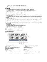
SB1 is a 1 channel temperature controller designed for flexible heating solutions such as heat trace of
pipelines (by controlling Jacket heater etc).
Features include:
Space-saving: 103 57 44 (Height Width Depth) [Instrument only]
Built-in SSR (Solid state relay): Instrument can be wired directly to heaters.
Data can be viewed locally by using the display, operation keys or loader
communication port.
Various ways to mount the instrument based on the pipe:
Pipe wrapping type, Pipe hanging type, Panel mounting type, etc.
UP to 31 units can be connected to the Host computer.
Communication interface: RS-485
Communication protocol: RKC communication or Modbus
Easy parameter setup via USB loader port
Saving parameter settings to a PC and copying parameters to other controllers becomes easy with
the USB port, a COM-K2 converter, and dedicated PROTEM2 software.
Download the software from the official RKC website: http://www.rkcinst.com/
SB1
Installation example
Host computer
RS-485
Jacket heater
SB1
SB1SB1
Pipe
Senso
r
input
Heate
r
output

1. OUTLINE
IMR02M04-E2 1-3
1.2 Input/Output and Function Blocks
This section describes the input/output and function blocks of the instrument.
Input processing
PV digital filter
PV bias
PV monitor
RTD
TC
SV1
SV2
SV monitor
COM-K2 must be used to connect to a
PC via the loader port.
MV monitor
Control output
OUT
(Contact open when error occurs)
Measured
input
Control output
Triac
Output
limiter
AUTO
MAN
: Monitor display
Marked
*: Optional
Set value
DI function assignment
SV selection
RUN/STOP transfer
AUTO/MAN transfer
Interlock release
DI is not available
with Communication
function.
DI *
Digital input
Dry contact
Communication function
is not available with DI.
RS-485
Protocol selections
Modbus
Control processing
PID control
ON/OFF control
Autotuning (AT)
Startup tuning (ST)
Fine tuning
Output limiter
Communication
processing
DO
Delay timer
Interlock
Energized/De-energized
Event 1 to 2 processing
Temperature alarm
Control loop break alarm
(LBA)
Monitor during RUN
Communication monitoring
FAIL
Event output
Relay contact
Event
FAIL output
SV selection
(Front key, DI,
communication)
Setting change rate limiter
Auto (AUTO)/Manual (MAN) transfer
(Front key, DI, communication)
Manual manipulated
output value
Interlock release
(Front key, DI,
communication
)
RUN/STOP transfe
r
(Front key, DI,
communication)
Communication
function *
RKC
communication
Loader
communication

1. OUTLINE
1-4 IMR02M04-E2
1.3 Checking the Product
Before using this product, check each of the following:
Model code
Check that there are no scratches or breakage in external appearance (case, front panel, or terminal, etc.)
Check that all of the items delivered are complete. (Refer to below)
Accessories
Q’TY Remarks
Instrument 1
Installation Manual (IMR02M01-E) 1 Enclosed with instrument
Quick Operation Manual (IMR02M02-E) 1 Enclosed with instrument
Parameter List (IMR02M03-E) 1 Enclosed with instrument
Instruction Manual (IMR02M04-E2)
1 This manual
(sold separately)
This manual can be downloaded from
the official RKC website:
http://www.rkcinst.com/english/
manual_load.htm.
Measured input/Control output connector [plug]
SB1P- C01
1 Optional (sold separately)
Power supply/Event input/output/Communication
connector [plug]
SB1P-C02
1 Optional (sold separately)
Fitting
SB1P-M01: Fitting for pipe wrapping type
SB1P-M02: Fitting for pipe hanging type
(Heat radiating cover)
SB1P-M03: Fitting for DIN rail mounting type
1 Optional (sold separately)
Strapping for pipe wrapping type
(Cross section: Extra heavy)
Width: 12.7 mm Length: 594 mm
SB1P-B01
Depending
on the order
quantity
Optional (sold separately)
Strapping for pipe hanging type
(Cross section: Heavy)
Width: 7.9 mm Length: 1000 mm
SB1P-B02
Depending
on the order
quantity
Optional (sold separately)
Operating tool for Measured input/Control output
connector
SB1P-C11
Depending
on the order
quantity
Optional (sold separately)
Push button (Connector operating lever)
for Measured input/Control output connector
SB1P-C12
Depending
on the order
quantity
Optional (sold separately)
Operating tool for Power supply/Event input/
Event output/Communication connector
SB1P-C13
Depending
on the order
quantity
Optional (sold separately)
ローダツール操作説明書 (IMR01W05-J)
1
別売り
If any of the products are missing, damaged, or if your manual is incomplete, please contact
RKC sales office or the agent.

1. OUTLINE
IMR02M04-E2 1-5
1.4 Model Code
Check that the product received is correctly specified by referring to the following model code list:
If the product is not identical to the specifications, please contact RKC sales office or the agent.
Suffix code
□
□□□-□-□*□□□□-□□□
(1) (2) (3) (4) (5) (6) (7) (8) (9) (
10
)(
11
)
Specifications
Suffix code
(1) (2) (3) (4) (5) (6) (7) (8) (9) (10) (11)
Control Method PID control with AT (Reverse action) F
Measured input and Range
Thermocouple K 0 to 800 C K04
Thermocouple K 0 to 999 F KB1
Thermocouple J 0 to 800 C J04
Thermocouple J 0 to 999 F JA8
RTD Pt100 0 to 400 C D17
RTD Pt100 0 to 800 F DB4
Control output Triac output T
Power supply voltage 100 to 240 V AC 4
Digital output (DO)
None
N
1 point 1
Digital input (DI)/
Communication function
None N
Digital input (1 point) D
Communication function RS-485 (RKC communication) 5
Communication function RS-485 (Modbus) 6
Mounting method
Without fitting (Panel mounting)
N
With fitting (Sold separately) 1
Quick start code
No quick start code N
Specify quick start code 1
Event 1 type
[Quick start code]
No code
No specify quick start code
N
Refer to Event Type Code Table. □
Event 2 type
[Quick start code]
No code
No specify quick start code
N
Refer to Event Type Code Table. □
Digital output assignment
[Quick start code]
No code
No specify quick start code
N
Event 1 1
Event 2 2
Logical OR of Event 1 and Event 2 3
Logical AND of Event 1 and Event 2 4
Event Type Code Table
Code Type Code Type
N
None
R
Deviation low with re-hold action
A
Deviation high
T
Deviation high/low with re-hold action
B
Deviation low
U
Band (High/Low individual setting)
C
Deviation high/low
V
SV high
D
Band
W
SV low
E
Deviation high with hold action
X
Deviation high/low (High/Low individual setting)
F
Deviation low with hold action
Y
Deviation high/low with hold action (High/Low individual setting)
G
Deviation high/low with hold action
Z
Deviation high/low with re-hold action (High/Low individual setting)
H
Process high
2
Control loop break alarm (LBA)
J
Process low
3
FAIL
K
Process high with hold action
4
Monitor during RUN
L
Process low with hold action
5
Output of the communication monitoring result
Q
Deviation high with re-hold action
SB1

1. OUTLINE
1-6 IMR02M04-E2
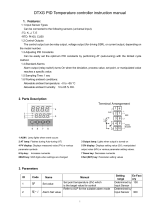
1.5 Parts Description
This section describes various display units and the key functions.
Front side
Upside Underside
Display [Green]
A
utotuning (AT) lamp [Green]
Output (OUT) lamp [Green]
Manual (MAN) mode lamp [Green]
STEP lamp [Green]
Measured value (PV) lamp [Green]
Digital output (DO) lamp [Red]
Up key
Down key
Set (SET) key
Shift (R/S) key
SET
R/S
SB1
888
A
T
OUT MAN
STEP
PV DO
Loader communication connector
(Standard equipment)
Protective earth (PE)
terminal
Measured input/Control output
connector [CN2]
Power supply/Event input/Event output/
Communication
connector [CN1]

1. OUTLINE
IMR02M04-E2
1-7
Display unit
Display [Green]
Displays Measured value (PV), Set value (SV), Manipulated output value (MV)
or various parameter symbols.
Indication lamps
Autotuning (AT) lamp [Green]
Flashes when Autotuning is activated. (After Autotuning is completed: AT lamp
will go out)
Light during Startup tuning (ST) execution.
Output (OUT) lamp [Green]
Lights when Output is turned on.
Manual (MAN) mode lamp [Green]
Lights when operated in Manual (MAN) mode.
STEP lamp [Green]
Lights when SV2 is selected for the Set value (SV).
Measured value (PV) lamp [Green]
Lights when the Measured value (PV) is displayed.
Digital output (DO) lamp [Red]
Lights when the Event output is turned on.
Operation keys
Set (SET) key
Used for calling up parameters and set value registration.
R/S
Shift (R/S) key
Shifts digits when settings are changed.
Used to switch monitor items, RUN/STOP, and modes.
Down key * Decreases numerals.
Up key * Increases numerals.
For switching to the Maintenance mode
* Also used to switch items within Mode switching (AUTO/MAN, Set data lock, and Interlock release).
To avoid damage to the instrument, never use a sharp object to press keys.
Connector/Terminal
Power supply/Event input/
Event output/Communication
connector [CN1]
The following signals are assigned: Power supply, Digital output (DO) [Event
output], Digital input (DI) [Event input] and Communication.
(DI and Communication cannot be selected at the same time.)
Measured input/Control output
connector [CN2]
The following signals are assigned: Sensor input (Measured input) and Control
output.
Loader communication connector
(Standard equipment)
Setting and monitoring on a personal computer (PC) is possible if the controller
is connected with our cable to a PC via our USB communication converter
COM-K2 (sold separately)
1
. Our communication software
2
must be installed on
the PC.
1
For the COM-K2, refer to COM-K2 Instruction Manual.
2
Only available as a download from the official RKC website.
http://www.rkcinst.com/.
Protective earth (PE) terminal
Terminals for Protective earth

1. OUTLINE
IMR02M04-E2
1-8
How to connect the controller to a PC via loader communication port
Connect the controller, COM-K2, and personal computer using a USB cable and a loader
communication cable. Make sure the connectors are oriented correctly when connecting.
The Loader port is only for parameter setup.
Loader communication can be used on a controller even when the Communication function
(optional) is not installed.
The loader communication corresponds to the RKC communication protocol “Based on
ANSI X3.28-1976 subcategories 2.5 and A4.”
A previous version of COM-K (version 1) can be also used. However, if communication tool
PROTEM2 is used using a COM-K, the PROTEM2 will not be supported by Windows 8 or
later.
USB cable 1 m
(COM-K2 accessory)
Connect to loader
communication connector
of the controller
Connect to USB
port of a personal
computer
Connect to loader
communication
connecter
Connect to
USB connecter
The device address for loader
communication is fixed at “0.”
The setting of the device address
is disregarded.
Loader
communication
connecto
r
SB1 Bottom View
Do not unplug the USB cable while the
power to the instrument is ON.
USB
communication
converter
COM-K2
Loader communication
cable 1.5 m (W-BV-01)
[COM-K2 optional]
Communication settings on the computer
(The following values are all fixed)
Communication speed: 9600 bps
Start bit: 1
Data bit: 8
Parity bit: Without
Stop bit: 1
Communication port of host computer
USB port: Based on USB Ver. 2.0
Communication tool PROTEM2
Software operation environment:
Consult the manual that
y
ou downloaded
/