
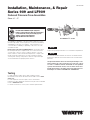
RP/IS-909S
No. 909QT-S 1
1
⁄2" shown
NOTICE
Inquire with governing authorities for local installation requirements
NOTICE
For Australia and New Zealand, line strainers should be installed
between the upstream shutoff valve and the inlet of the backflow
preventer.
Its important that this device be tested periodically in com-
pliance with local codes, but at least once per year or more
as service conditions warrant. If installed on a fire sprinkler
system, all mechanical checks, such as alarm checks and
backflow preventers, should be flow tested and inspected
internally in accordance with NFPA 13 and NFPA 25.
Installation, Maintenance, & Repair
Series 909 and LF909
Reduced Pressure Zone Assemblies
Sizes:
3
⁄4" – 2"
Local building or plumbing codes may require modifications to the
information provided. You are required to consult the local building
and plumbing codes prior to installation. If this information is not
consistent with local building or plumbing codes, the local codes
should be followed.
Need for Periodic Inspection/Maintenance: This product must
be tested periodically in compliance with local codes, but at least
once per year or more as service conditions warrant. Corrosive
water conditions, and/or unauthorized adjustments or repair could
render the product ineffective for the service intended. Regular
checking and cleaning of the product’s internal components helps
assure maximum life and proper product function.
WARNING
!
Read this Manual BEFORE using this equipment.
Failure to read and follow all safety and use information
can result in death, serious personal injury, property
damage, or damage to the equipment.
Keep this Manual for future reference.
Testing
For field testing procedure, refer to Watts installation sheets
IS-TK-DP/DL, IS-TK-9A, IS-TK-99E and IS-TK-99D found on www.
watts.com.
For other repair kits and service parts, refer to our Backflow
Prevention Products Repair Kits & Service Parts price list PL-RP-BPD
found on www.watts.com.
For technical assistance, contact your local Watts representative.

1. Backflow preventers must be installed in high-visibility locations
in order to allow for immediate notice of telltale discharge or
other malfunction. This location should also facilitate testing and
servicing, and protect against freezing and vandalism.
2. Installing a backflow preventer in a pit or vault is not recom-
mended as flooding of the pit will cause a crossconnection.
Ensure that all local codes and required safety provisions
are met. An air gap below the relief port must be maintained so
as to avoid, flooding and submersion of the assembly, which
may lead to a cross-connection.
3. A strainer should be installed ahead of the backflow preventer to
protect all internal components from unnecessary fouling.
CAUTION
!
Do not install a strainer ahead of the backflow preventer on seldom-
used, emergency water lines (i.e. fire sprinkler lines). The strainer
mesh could potentially become clogged with debris present in the
water and cause water blockage during an emergency.
4. Normal discharge and nuisance spitting are accommodated by
the use of a Watts air gap fitting and a fabricated indirect waste
line. Floor drains of the same size MUST be provided in case of
excessive discharge.
5. When a 909 and LF909 Series backflow preventer is installed for
dead-end service applications (i.e. boiler feed lines, cooling
tower makeup or other equipment with periodic flow require-
ments), discharge from the relief vent may occur due to water
supply pressure fluctuation during static no-flow conditions. A
check valve may be required ahead of the backflow preventer.
*Please see “Troubleshooting”, page 7, prior to installation.
6. The 909 and LF909 Series backflow preventer is designed so
that the critical level of the relief valve is positioned below the
first check. This unique feature allows the valve to be installed
either vertically or horizontally.
7. Installation procedures must comply with all state and
local codes. *Please see page 3 for specific installation proce-
dures.
8. Prior to installation, thoroughly flush all pipe lines to remove any
foreign matter.
9. Start up at Initial Installations and After Servicing: The down-
stream shutoff should be closed. Slowly open upstream shutoff
and allow the backflow preventer to fill slowly. Bleed air at each
test cock. When backflow preventer is filled, slowly open the
downstream shutoff and fill the water supply system. This is nec-
essary to avoid dislodging O-rings or causing damage to internal
components.
10. Test: The 909 and LF909 Series backflow preventer must be
tested by a certified tester at the time of installation in order to
ascertain that the assembly is in full working order and may be
relied upon to protect the safe drinking water as per applicable
standards.
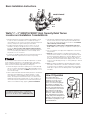
First
Check
Relief
Valve
Second
Check
909QT/LF909QT
How It Operates
The unique relief valve
construction incorporates two
channels: one for air, one for
water. When the relief valve
opens, as in the accompanying
air-in/water-out diagram, the
right hand channel admits air to
the top of the reduced pressure
zone, relieving the zone vacuum.
The channel on the left then
drains the zone to atmosphere.
Therefore, if both check valves
foul, and simultaneous negative
supply and positive backpressure
develops, the relief valve uses the
air-in/water-out principle to stop
potential backow.
Reduced
Pressure
Zone
Water Out
Air In
2
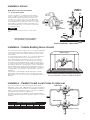
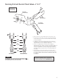
Basic Installation Instructions
Watts
3
⁄4" – 2" 909QT/LF909QT High Capacity Relief Series:
Location and Installation Considerations
For repair kits and parts, refer to our Backflow
Prevention Products Repair Kits & Service Parts
price list PL-RP-BPD found on www.watts.com.

Now available, WattsBox Insulated Enclosures,
for more information, send for ES-WB or ES-WB-T.
FIBERGLASS WattsBox
Min. 12"
ASSE approved for vertical installation
3
⁄4" – 2" flow up and down
3
For indoor installations, it is important that the valve be
easily accessible to facilitate testing and servicing. Series
909 and LF909 may be installed either vertically or hori-
zontally. If it is located in a line close to wall, be sure the
test cocks are easily accessible. A drain line and air gap
should be piped from the relief valve connection as shown,
where evidence of discharge will be clearly visible and so
that water damage will not occur. Therefore, never install
in concealed locations.
NOTICE
Test cock must be located on the first or inlet shutoff
valve.
Flow
Relief Valve
Below First Check
Valve
Air In
Water
Out
Main
▼
Min.
4
1
⁄2"
▼
▼
Air*
Gap
First
Check
Valve
909QT-S/
LF909QT-S
Vertical Installation - Upward Flow
*For Air Gap information contact your technical
sales representative or refer to ES-AG/EL/TC.
In an area where freezing conditions do not occur, Series 909/LF909
can be installed outside of a building. The most satisfactory installa-
tion is above ground and should be installed in this manner when-
ever possible.
In an area where freezing conditions can occur, Series 909/LF909
should be installed above ground in an insulated enclosure.
Series 909/LF909 may be installed in a vertical or horizontal line
and in an accessible location to facilitate testing and servicing. A
discharge line should be piped from the air gap at the relief valve
connection making sure there is adequate drainage. Never pipe the
discharge line directly into a drainage ditch, sewer or sump. Series
909 and Series LF909 should never be installed where any part of
the unit could become submerged in standing water. Consideration
should be given to the installation of external support structure as
applicable.
It is generally recommended that backflow preventers never be
placed in pits unless absolutely necessary, and then only, when
approved by local codes. In such cases, a modified pit installation is
preferred.
Two or more smaller size valves can be piped in parallel (when
approved) to serve a larger supply pipe main. This type of installation
is employed where increased capacity is needed beyond that provid-
ed by a single valve and permits testing or servicing of an individual
valve without shutting down the complete line.
The number of valves used in parallel should be determined by the
engineer’s judgement based on the operating conditions of a specific
installation.
Installation Indoors
Installation - Outside Building Above Ground
Installation - Parallel Consult Local Codes for Approval
909QT-S/LF909S
909QT-S/LF909QT-S
Air Gap
(Drawings not to scale)
TABLE ONE - CAPACITY REQUIRED FOR SYSTEM
50 gpm 100 gpm 150 gpm 200 gpm 250 gpm 350 gpm
Two
3
⁄4" Two 1" Two 1
1
⁄4" Two 1
1
⁄2" Two 1
1
⁄2" Two 2"
Devices Devices Devices Devices Devices Devices
Table shows total capacity provided with dual valve installations of various sizes.

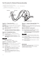
A. All needle valves must be closed on test kit.
B. Open test cock No. 4 and flush test cocks Nos. 1, 2 and 3 on reduced pressure
assembly then close test cock No. 4.
C. Attach hoses as shown. Bleed air from kit, close No. 2 shutoff.
909QT/LF909QT shown
No. 2 shutoff
Bleed Valve A
Bleed Valve B
High
(red)
Bypass
(yellow)
Low
(blue)
Test No. 1 - Check Valve No.2
Purpose: To test check valve No. 2 for tightness against
reverse ow.
Requirements: Valve must be tight against reverse ow under all
pressure differentials.
Step 1 Slowly open the needle valve “A” high side (red) and “C”
bypass (yellow). Keep the “B” low (blue) closed.
Step 2 Open test cock No. 4.
Step 3 Indicated pressure differential will decrease slightly. If
pressure differential continues to decrease (until the vent
opens) the No. 2 check valve is reported as “leaking”.
Test No. 2 - Shuto Valve No. 2
Purpose: To test shutoff valve No. 2 for tightness.
Step 1 After passing Test No. 1, continue to test No. 2 by
closing test cock No. 2.
Step 2 The indicated pressure differential will decrease slightly.
If pressure differential continues to decrease
(approaching “zero”), the No. 2 shutoff valve is reported
to be “leaking”.
NOTICE
A leaking No. 2 shutoff will give a
false reading in tests No. 3 and 4.
Test No. 3 - To Test No. 1 Check Valve
Purpose: To test check valve No. 1 for tightness.
Requirements: Valve must be tight against reverse ow under all
pressure differentials.
Step 1 Close needle valve “A” high side (red) and open test
cock No. 2
Step 2 Close test cock No. 4. Disconnect bypass hose (yellow)
at test cock No. 4.
Step 3 Open needle valve “B” low (blue) and “C” bypass
(yellow), bleeding to atmosphere, then closing needle
valve “B” (blue) restores the system to a normal
static condition.
Step 4 Observe the pressure differential gauge. If there is a
decrease in the indicated value, the No. 1 check valve is
reported as “leaking”.
Test No. 4 - Pressure Dierential Relief Valve
Purpose: To test operation of pressure differential
relief valve.
Requirements: The pressure differential relief valve must operate
to maintain the “zone” between the two check valves at least 2psi
less than the supply pressure.
Step 1 Close needle valve “C” bypass (yellow).
Step 2 Open needle valve “A” high side (red).
Step 3 Open needle valve “B” low (blue) very slowly until the
differential gauge needle starts to drop.
Step 4 Hold the valve at this position and observe the gauge
reading at the moment the rst discharge is noted from
the relief valve. Record this as the opening differential
pressure of the relief valve.
NOTICE
It is important that the differential gauge needle drops slowly.
Step 5 Close test cocks Nos. 2 and 3. Remove hose from test
cocks Nos. 2 and 3.
Step 6 Use bypass hose (yellow) to relieve pressure from test
kit by opening needle valve “A”, “B” and “C” and bleed
valves “A” and “B”.
Step 7 Remove all test equipment and open No. 2 shutoff
valve of the device.
4
CAUTION
!
To prevent freezing, hold Test Kit vertically to drain differential
gauge and hoses prior to placing in case.
For additional testing information, refer to IS-TK-DP/DL,
IS-TK-9A, IS-TK-99E or IS-TK-99D.
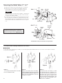
Test Procedure for Reduced Pressure Assembly

5
NOTICE
The springs and covers of the first and second check valves are not
interchangeable. The heavier spring loaded module should be in the first
check and the lighter in the second check module.
Cover
Cover
O-ring
Spring
Disc
Assembly
Seat
Seat
O-ring
First Check
Second Check
Servicing First and Second Check Valves
3
/4" to 2"
No special tools
required to service
Series 909/LF909
First Check
Service Parts Kit
Second Check
Service Parts Kit
Body
Relief Valve
Service Parts Kit
For repair kits and parts, refer to our Backflow
Prevention Products Repair Kits & Service Parts
price list PL-RP-BPD found on www.watts.com.
1. Remove the four screws holding the first check valve cover.
2. Lift off the first check valve cover. The check valve inside will
come out with the cover and is attached with a bayonet type
locking arrangement.
3. Holding the check valve module in both hands, rotate the
assembly quarter turn. This will disengage the disc assembly,
spring and seat cover into individual components.
4. The disc assembly may be cleaned and reassembled, or
depending upon its condition, it may be discarded and replaced
with a new assembly from theservice kit. O-rings should be
cleaned or replaced as necessary and lightly greased with the
FDA approved silicon grease which is also furnished with the
service kit.
5. Reassemble the check valve module in the reverse order.
Service is identical for both the first and second check valves.
For further details contact your local technical sales rep-
resentative.

1. Remove the four bolts that hold the relief valve cover in place.
2. Remove the cover. The stainless steel adapter, with O-ring
attached will be free to be removed simultaneous with the
removal of the cover. Pull out the relief valve assembly.
NOTICE
The spring tension in the relief valve assembly is contained in the
design of the relief valve; therefore, the relief can be removed in
a one-piece spool-type assembly.
3. The relief valve seat and disc may be cleaned without disassem-
bly of the relief valve assembly. If it is determined that the relief
valve diaphragm and/or disc should be replaced, the relief valve
module can be readily disassembled without the use of special
tools.
To Prevent Shaft Damage Assemble As Shown:
CAUTION
!
If cover will not press against body, assembly is crooked and tightening bolts will bend shaft. Do not force the cover into place as damage
may result from misalignment.
Figure 1
Figure 2
Figure 3
Figure 1:
To assemble the Relief Valve Assembly
have a screwdriver ready.
Figure 2:
Depress the Relief Valve Assembly,
carefully guiding it against the two pound
spring load. When properly aligned, the
piston is in the cylinder bore. Insert the
screwdriver as shown.
Figure 3:
The Relief Valve Assembly is held
encapsulated by the screwdriver. You
should now have both hands free to
bolt down the cover. Insert and snug
two bolts 180° apart to hold the cover.
Finish inserting the remaining bolts and
snug up evenly, alternating until secure.
Remove the screwdriver.
Disc Assembly
Piston
O-ring
Relief Valve
Assembly
RV O-Ring
Stem
Seat
Body
Cover
Diaphragm
Piston
6
Cover
Seat
O-ring
Size
3
⁄4” – 1”
Disc Assembly
(2) Piston
O-rings
Relief Valve
Assembly
(2) RV O-Rings
Stem
Seat
Diaphragm
Piston
Seat
O-ring
Size 1
1
⁄4" – 2"
For further details contact your local technical sales representative.
Servicing the Relief Valve
3
/4" to 2"
For repair kits and parts, refer to our Backflow
Prevention Products Repair Kits & Service Parts
price list PL-RP-BPD found on www.watts.com.

7
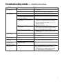
Problem Cause Solution
A. Valve spits periodically
from the vent
A.1 Fluctuating supply pressure. A.1 Install a soft seated check valve immediately upstream
of the de vice.
A.2 Fluctuating downstream pressure A.2 Install a soft seated check valve downstream of the
device close as possible to the shutoff valve.
B. Valve drips continually
from the vent
B.1 Fouled first check B.1 Flush valve. If flushing does not resolve problem, dis-
assemble valve and clean or re place the first check.
B.2 Damage or fouled relief valve seat. B.2 Clean or replace the relief valve seat.
B.3 Relief valve piston O-ring not free to
move due to pipe scale, dirt or build
up of mineral deposits.
B.3 Clean, grease or replace the piston O-ring.
B.4 Excessive back pressure, freezing, or
water hammer has distorted the sec-
ond check.
B.4 Elim i nate source of excessive backpressure or water
hammer in the system downstream of the device. Use
Watts No. 15 to eliminate water hammer. Replace
defective second check assembly.
In case of freezing; thaw, dis as sem ble and inspect
internal components.
Replace as necessary.
B.5 Electrolysis or relief valve seat or first
check seats.
B.5 Replace relief valve seat or inlet cover.
Electrically ground the piping system and/or electri-
cally isolate the device with plastic pipe immediately
upstream and down stream of the device.
B.6 Valve improperly reassembled. B.6 If valve is dis as sem bled during installation, caution
must be exercised to install check springs in their
proper location.
C. Valve exhibits high
pressure drop.
C.1 Fouled strainer. C.1 Clean strainer element or replace.
C.2 Valve too small for flows encountered. C.2 Install proper size device based upon
flow requirements.
D. No water flows down-
stream of valve.
D. Valve installed backwards. D. Install valve in accordance with flow direction arrow.
E. Valve does not test
properly
E.1 Follow manufacturer’s test procedure E.1, E.2 Clean or replace gate valve with full port ball
valves or resilient wedge shutoff valves.
E.2 Leaky downstream gate valve.
F. Valve quickly and
repeatedly fouls
following servicing.
F. Debris in pipe line is too fine to be
trapped by strainer.
F. Install finer mesh strainer element in the strainer.
G. Winterization of back-
flow preventers.
G. Electric heat-tape wrap closely together around valve
body. Build a small shelter around the valve
with a large light bulb installed and left on at all times.
If supply line is not used during the winter, removal
of the com plete body is the best. This would create
an air gap to eliminate any possible backflow.
Troubleshooting Guide — Backflow Preventers

For additional information, visit our web site at: www.watts.com
RP-IS-909S 2020 EDP# 0834246 © 2020 Watts
Limited Warranty: Watts (the “Company”) warrants each product to be free from defects in material and workmanship under normal usage for a period of one year from the date of original shipment.
In the event of such defects within the warranty period, the Company will, at its option, replace or recondition the product without charge.
THE WARRANTY SET FORTH HEREIN IS GIVEN EXPRESSLY AND IS THE ONLY WARRANTY GIVEN BY THE COMPANY WITH RESPECT TO THE PRODUCT. THE COMPANY MAKES NO OTHER
WARRANTIES, EXPRESS OR IMPLIED. THE COMPANY HEREBY SPECIFICALLY DISCLAIMS ALL OTHER WARRANTIES, EXPRESS OR IMPLIED, INCLUDING BUT NOT LIMITED TO THE IMPLIED
WARRANTIES OF MERCHANTABILITY AND FITNESS FOR A PARTICULAR PURPOSE.
The remedy described in the first paragraph of this warranty shall constitute the sole and exclusive remedy for breach of warranty, and the Company shall not be responsible for any incidental,
special or consequential damages, including without limitation, lost profits or the cost of repairing or replacing other property which is damaged if this product does not work properly, other costs
resulting from labor charges, delays, vandalism, negligence, fouling caused by foreign material, damage from adverse water conditions, chemical, or any other circumstances over which the Company
has no control. This warranty shall be invalidated by any abuse, misuse, misapplication, improper installation or improper maintenance or alteration of the product.
Some States do not allow limitations on how long an implied warranty lasts, and some States do not allow the exclusion or limitation of incidental or consequential damages. Therefore the above
limitations may not apply to you. This Limited Warranty gives you specific legal rights, and you may have other rights that vary from State to State. You should consult applicable state laws to
determine your rights. SO FAR AS IS CONSISTENT WITH APPLICABLE STATE LAW, ANY IMPLIED WARRANTIES THAT MAY NOT BE DISCLAIMED, INCLUDING THE IMPLIED WARRANTIES OF
MERCHANTABILITY AND FITNESS FOR A PARTICULAR PURPOSE, ARE LIMITED IN DURATION TO ONE YEAR FROM THE DATE OF ORIGINAL SHIPMENT.
USA: T: (978) 689-6066 • F: (978) 975-8350 • Watts.com
Canada: T: (888) 208-8927 • F: (905) 332-7068 • Watts.ca
Latin America: T: (52) 55-4122-0138 • Watts.com
-
 1
1
-
 2
2
-
 3
3
-
 4
4
-
 5
5
-
 6
6
-
 7
7
-
 8
8


Ask a question and I''ll find the answer in the document
Finding information in a document is now easier with AI
Related papers
-
Watts 0794079 Installation guide
-
Watts 912HP 1 Installation guide
-
Febco TK-1 Installation guide
-
Watts SR909-OSY 8 Installation guide
-
-
-
-
Ames Fire & Waterworks ATG-1 Installation guide
-
-
Other documents
-
 T & S Brass & Bronze Works B-0917 Datasheet
-
Dwyer Series BTK User manual
-
Zurn WILKINS 950LF Installation, Testing, Maintenance Instructions
-
Rain Bird HVF Installation guide
-
Ames Fire & Waterworks LFM300,M200,M300 Installation guide
-
Zurn Wilkins 3-375ASTROSY-A User manual
-
 Dormont Mfg C500 Installation guide
-
-
Zurn Wilkins 212-375OSY Installation guide
-

