
OJ Microline
®®
Type OCD2
IINNSSTTRRUUCCTT IIOONNSS
English
T
ype OCD2 is for flush mounting in a wall
socket. A baseplate for external wall mounting
i
s available.
W
ARNING – Important Safety Instructions
Isolate supply before carrying out any
i
nstallation or maintenance work on this control
u
nit and associated components. This control
unit and associated components should only be
installed by a competent person (i, e qualified
e
lectrician). Electrical installation to be in
a
ccordance with latest appropriate Statutory
Regulations.
M
ounting of sensor
F
loor sensor: Placed in an approved non
conductive installation pipe in accordance with
E
N 61386-1, which is embedded in the floor.
(
fig. 3) The pipe is closed in the end and placed
as high as possible in the concrete layer. The
installation pipe must be centered in between
t
he heating cable.
Sensor cable can be extended up to 100 m. by
m
eans of a separate cable. If the extension
cable is lighter than H05VV-F, it shall equally be
installed in an unbroken installation pipe
between the sensor cable and the extension
cable. Two remaining cores of a multi-core
cable which, for example, supplies current to
the floor heating wires, must not be used. The
switching peaks of such current supply lines
may create interfering signals that prevent
optimum controller function. If a shielded cable
is used, the shield must not be earthed but
must be connected to terminal 6. The two-core
cable must be placed in a separate pipe.
Mounting of thermostat with built-in sensor
(fig. 4)
The room sensor is used for comfort
temperature regulation in rooms. The
thermostat is mounted on the wall with free air
circulation about 1.6 m above the floor. Draught,
direct sunlight, or any other direct heating outlet
must be avoided. No external sensor is to be
connected.
Mounting of thermostat
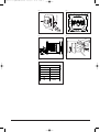
1. Release the front cover ONLY by inserting a
small screwdriver into the air grills on both
sides of the thermostat (see fig. 1).
DO NOT open the thermostat by releasing
the four fixing clips on the back.
2. Connect cables according to the diagram
(fig. 2)
3. The thermostat is mounted in the wall
socket. The cover and the frame are
remounted.
Operation
The first time the thermostat is connected, time
and day must be set:
Setting of time
(the clock flashes during setting)
Setting of day
(day flashes during setting)
Programming
See user’s manual.
Fault location
If the sensor is disconnected or short -circuited,
☞
☞
the heating system is cut out. The sensor can
be checked according to the resistance table
f
ig. 5.
Error codes
E
0: Internal error. The thermostat must be
r
eplaced.
E
1: Built-in sensor short-circuited or
disconnected.
E
2: External sensor short-circuited or
d
isconnected.
CE marking
A
ccording to the following standards,
E
MC EN 61000-6-1: 2001,
EN 61000-6-3: 2001
LVD: EN 60730-1, EN 60730-2-9
C
lassification
The product is a class II device (enhanced
i
nsulation) and the product must be connected
t
o the following leads,
Term. 1: Phase (L) 230 V±15%, 50/60 Hz
Term. 2: Neutral (N)
T
erm. 3–4: Load max. 16A, 3.600W
Environment and recycling
P
lease help us to protect the environment by
disposing of the packaging in accordance with
the national regulations for waste processing.
Recycling of obsolete appliances
Appliances with this label must not
be disposed off with the general
waste. They must be collected
separately and disposed off
according to local regulations.
OJ Electronics A/S
Stenager 13B · DK - 6400 Sønderborg
Tel: +45 73 12 13 14 · Fax: +45 73 12 13 13
[email protected] · www.oj.dk
Deutsch
Typ OCD2 ist für Unterputzmontage in einer
Wanddose vorgesehen. Als Zubehör ist eine
Unterlage für Aufwandmontage erhältlich.
ACHTUNG – Wichtiger Sicherheitshinweis
Vor der Ausführung von Installations- oder
Instandhaltungsarbeiten an dieser Regel einheit
und zugehörigen Komponenten ist die
Spannungsversorgung zu unterbrechen. Diese
Regeleinheit und zugehörige Komponenten
dürfen nur von einer fachlich befähigten Person
(d. h. autorisierter Elektriker) installiert werden.
Die Elektro installation muss in Übereinstimmung
mit den neuesten EU-Richtlinien für elektrische
Betriebsmittel und den geltenden dies -
bezüglichen Rechtsvorschriften erfolgen.
Montage des Fühlers
Bodenfühler: Platzierung in einem gemäß EN
61386-1 zugelassenen nichtleitenden
Installations rohr, das im Boden eingelassen ist
(Abb. 3). Das Rohr ist am Ende verschlossen
und so hoch wie möglich in der Betonschicht
platziert. Das Installationsrohr muss zwischen
den Heizkabelserpentinen zentriert werden.
Das Fühlerkabel kann mit einem separaten
Kabel bis zu 100 m verlängert werden. Ist das
Verlängerungskabel dünner als H05VV-F, muss
es ebenfalls in einem zwischen Fühlerkabel und
Thermostat durchgehenden Installationsrohr
verlegt werden. Zwei freie Leiter eines
M
ehrleiterkabels, das beispiels weise Boden -
h
eizdrähte mit Strom versorgt, dürfen nicht
verwendet werden. Die Schalts pitzen einer
d
erartigen Stromversorgung können das Signal
b
eeinträchtigen und eine optimale Regler -
f
unktion verunmöglichen. Wird ein
abgeschirmtes Kabel verwendet, darf die
A
bschirmung nicht geerdet werden, sondern ist
a
n Klemme 6 anzuschließen. Das
Zweileiterkabel ist in einem separaten Rohr zu
verlegen.
M
ontage des Thermostaten für Modelle mit
eingebautem Fühler (Fig. 4)
Der Raumfühler wird für die Regelung der
K
omforttemperatur in Räumen verwendet. Der
T
hermostat wird an einer Wand mit freier
Luftzirkulation und etwa 1,6 m über dem Boden
m
ontiert. Zugluft, direkter Sonnenschein oder
e
ine andere direkte Wärmebeeinflussung sollten
vermieden werden. Ein externer Fühler soll nicht
angeschlossen werden.
M
ontage des Thermostaten
1. Einen Schraubenzieher in den Luftgittern auf
d
en beiden Seiten des Thermostaten
einstecken und den Deckel dadurch lösen
(siehe Abb. 1). Der Thermostat darf nicht
durch Lösen der vier Schnappschlösse hinten
geöffnet werden.
2. Kabel anschließen laut Diagramm (Fig. 2).
3. Den Thermostaten in der Wanddose
montieren.
- Deckel und Rahmen wieder anmontieren.
Inbetriebnahme
Beim ersten Anschluss des Thermostaten
werden Zeit und Tag eingestellt:
Einstellung von Zeit (die Uhr blinkt
während der Einstellung)
Einstellung von Tag
(Tag blinkt während der Einstellung)
Programmierung
Siehe Benutzeranleitung.
Fehlersuche
Falls der Fühler ausgeschaltet oder
kurzgeschlossen ist, wird die Wärmeanlage
ausgeschaltet. Der Fühler kann laut der Wider-
standstabelle in Fig. 5 kontrolliert werden.
Fehlercodes:
E0: Interner Fehler. Der Thermostat muss
ausgewechselt werden.
E1: Der eingebaute Fühler ist kurzgeschlossen
oder ausgeschaltet.
E2: Der externe Fühler ist kurzgeschlossen oder
ausgeschaltet.
CE-Markierung
Laut folgenden Standards:
EMC: EN 61000-6-1: 2001,
EN 61000-6-3: 2001
LVD: EN 60730-1, EN 60730-2-9
Klassifikation
Das Produkt ist ein Klasse II Gerät (verstärkte
Isolierung) und das Produkt muss an folgende
Leiter angeschlossen werden:
Term. 1: Phase (L) 230 V ±15%, 50/60 Hz
Term. 2: Null (N)
Term. 3–4: Belastung max. 16A, 3.600W
☞
☞
1
5
7570A 09/09 (DJU)
© 2009 OJ Electronics A/S · ® The OJ trademark is a registred trademark belonging to OJ Electronics A/S
57570A-09-09.qxd:skabelon-A4 15/09/09 13:12 Side 1
Page is loading ...
Page is loading ...
Page is loading ...
Page is loading ...

6 © 2009 OJ Electronics A/S · ® The OJ trademark is a registred trademark belonging to OJ Electronics A/S
57570A-09-09.qxd:skabelon-A4 15/09/09 13:13 Side 6

© 2009 OJ Electronics A/S · ® The OJ trademark is a registred trademark belonging to OJ Electronics A/S
57570A
57570A-09-09.qxd:skabelon-A4 15/09/09 13:13 Side 7

© 2009 OJ Electronics A/S · ® The OJ trademark is a registred trademark belonging to OJ Electronics A/S
BR929A10
F
ig. 1
BR929A02
F
ig. 3
BR929A08
Sensor
Temp.(˚C) Value (ohm)
-10
0
10
20
30
64000
38000
23300
14800
9700
F
ig. 5
BR929A05
N
SENSOR
1
2
3 4 5 6
MAX 16A
3600W
230VAC
L
F
ig. 2
F
ig. 4
57570A-09-09.qxd:skabelon-A4 15/09/09 13:13 Side 8
-
 1
1
-
 2
2
-
 3
3
-
 4
4
-
 5
5
-
 6
6
-
 7
7
-
 8
8


OJ Electronics OCD2 Operating instructions
- Type
- Operating instructions
- This manual is also suitable for
Ask a question and I''ll find the answer in the document
Finding information in a document is now easier with AI
in other languages
- français: OJ Electronics OCD2 Mode d'emploi
- Deutsch: OJ Electronics OCD2 Bedienungsanleitung
- Nederlands: OJ Electronics OCD2 Handleiding
- dansk: OJ Electronics OCD2 Betjeningsvejledning
- polski: OJ Electronics OCD2 Instrukcja obsługi
- svenska: OJ Electronics OCD2 Bruksanvisningar
Related papers
-
 Arnold Rak OCC2 Owner's manual
-
 Arnold Rak Room thermostat Surface-mount 7 day mode 5 up to 40 °C User manual
-
OJ Electronics OTN Operating instructions
-
-
-
-
-
-
-


Other documents
-
AEG FRTD 902 User manual
-
Grundfos PM 1 Installation And Operating Instructions Manual
-
 Watts Industries WFHTRF-HC User manual
-
-
STIEBEL ELTRON RTF-TC Operation Instruction
-
Danfoss Floor Sensor for Icon thermostats Installation guide
-
-
Tefal 39398125 Owner's manual
-
DeLonghi HCO420F Owner's manual
-
Tyco TA Operation And Use Manual
