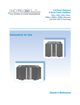
iBias Power Amplifier
Duo 125, 175, and 300 Stereo Amplifiers
Solo 375 and Solo 575 Mono Amplifiers
Trio 300 Three Channel Amplifier
Chorus 4200, 5200, and 7200 Multi Channel Amplifiers
SETUP GUIDE
Getting Started
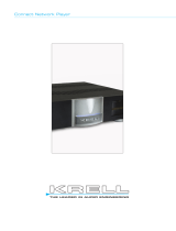
THE LEADER IN AUDIO ENGINEERING
Krell’s history is rich with breakthrough Class A amplifiers that have helped build
the Krell legacy of offering the best sounding amplifiers available. Audiophiles have
always considered Class A technology to be the best sounding operating state for
amplifiers. However, despite Class A’s unrivaled sound quality, it has fallen out
of fashion because of recent demands to reduce power consumption and heat in
home electronics products. Krell engineering took this challenge and redefined the
meaning of high performance power amplifier. Our goal – unmatched performance,
elegant design, and a compelling array of features. The breakthrough, iBias, a
patent pending circuit delivering Class A operation without the excessive heat
and wasted energy of conventional designs, housed in a striking new form factor,
with network connectivity for advanced access and monitoring. The sound is open
and unconstrained, in a manner that rivals live performance and the true sound of
voices and instruments. Music and dialogue are reproduced with a richness, detail,
and startling dynamics that fill a room.The iBias amplifier is easy to operate and
integrate into your system.
Do not place the amplifier where it could be exposed to dripping or splashing.
Do not remove or bypass the ground pin on the end of the AC cord. This may cause radio
frequency interference (RFI) to be introduced into your playback system.
The ventilation slots on the top and bottom of the amplifier as well as the fan openings on the
back must be unobstructed at all times during operation. Do not place flammable material on top
of or beneath the component.
Turn off all systems’ power before connecting the amplifier to any component.
Make sure all cable terminations are of the highest quality, free from frayed ends, short circuits, or
cold solder joints.
THERE ARE NO USER-SERVICEABLE PARTS INSIDE ANY KRELL PRODUCT.
1. Open the shipping box and remove the top layer of foam. You will see these items:
2. Carefully remove all items from the shipping box.
3. Place the amplifier in a safe location and remove the protective plastic wrapping.
Place the iBias amplifier on a firm, level surface, away from excessive heat, humidity,
or moisture. The amplifier requires at least one inch (2.54 cm) of clearance on each
side and at least two inches (5 cm) of clearance above to provide adequate ventilation.
Installations inside cabinetry may need extra ventilation.
WARNINGS
Krell iBias Amplifier 1
Unpacking
Krell Industries, LLC., 45 Connair Road, Orange, CT 06477-3650 USA
TEL 203-799-9954, FAX 203-799-9796
Connecting the
iBias Amplifier
to Your System
Because of its powerful amplifier channels and high-capacity power supply, iBias
amplifiers will benefit from a dedicated AC circuit. Avoid connections through extension
cords or multiple AC adapters. High quality 20 amp AC strips are acceptable. Please
contact your authorized Krell dealer or distributor before using any devices designed to
alter or stabilize the AC power.
Follow these steps to connect an iBias amplifier to your system.
1. Make sure all power sources and components are off before connecting inputs and
outputs.
2. Neatly organize the wiring between the iBias amplifier and all system components.
Separate AC wires from audio cables to prevent hum or other unwanted noises from
being introduced into the system.
3. Connect the left and right loudspeaker cables to the amplifier's left and right
loudspeaker output terminals (14).
4. Connect the left and right outputs of your preamplifier or processor to the appropriate
analog inputs (15, 16, 17) on the iBias amplifier.
5. Plug the AC cord into the IEC connector (22) on the back panel of the iBias amplifier.
Plug the remaining end into the AC wall receptacle. Move the Power Breaker Switch
on the rear panel to the up position. The red stand-by indicator (2) illuminates and the
display shows the model number, firmware version, serial number, and IP address.
Note
Use only the power cord provided with the iBias amplifier to make the connection to AC power.
Operation with a power cord other than the one supplied by Krell can induce noise, limit current, or
otherwise impair the ability of the iBias amplifier to perform optimally.
When powering up any system, alway turn amplifiers on last.
When powering down, always turn amplifiers off first.
1.
When the amplifier is in stand-by mode, with the red stand-by indicator (2)
illuminated, turn the amplifier on by pressing the power button on the front panel
(1).
There are audible clicks. The blue power indicator (2) illuminates. The display will
show the IP Address and model number and then turn off. The iBias amplifier is
now in the operational mode.
2. With the preamplifier or processor in the mute position, or the volume control fully
attenuated, select a source.
3. Start playing the source.
4. Set the volume to a comfortable listening level using the preamplifier or processor
volume control.
5. To turn the amplifier off, press the power button on the front panel (1). The red
stand-by indicator (2) illuminates.
It is now safe to turn off the rest of the system.
4 Krell iBias Amplifier
Operating the
iBias Amplifier
This product complies with the
EMC directive (89/336/EEC)
and the low-voltage directive
(73/23/EEC).
1 iBias amplifier chassis
1 IEC connector (AC power) cord
1 12V Trigger cable
1 Setup Guide
Placement
AC POWER GUIDELINES
MODEL: SERIAL NUMBER:
Overview
This CLASS 1 apparatus must
be connected to a MAINS
socket outlet with a protective
earthing connection.
Krell recommends using balanced
interconnect cables. Balanced
interconnect cables not only
can minimize sonic loss but are
also immune to induced noise,
especially with installations using
long cables. Balanced connections
have 6 dB more gain than single-
ended connections. When level
matching is critical, keep this gain
value in mind. For the Solo 375
or Solo 575, Krell recommends
the use of CAST. A Krell exclusive
technology, a Krell system
connected with Krell CAST MMF
cable is the fullest expression of
Krell engineering.
Note
Save all packing materials.
If you need to ship the iBias
amplier in the future, repack
th unit in its original packaging
to prevent shipping damage.