Page is loading ...
Installation - Parts
XM Plural-Component
OEM Sprayer
313292G
EN
For spraying two-component epoxy and urethane protective coatings
in non-hazardous locations.
For professional use only.
See page 6 for model information.
See page 31 for maximum working pressure.
For patent information, see www.graco.com/patents
Important Safety Instructions
Read all warnings and instructions in this
manual. Save these instructions.

2 313292G
Contents
Related Manuals . . . . . . . . . . . . . . . . . . . . . . . . . . . 3
Warnings . . . . . . . . . . . . . . . . . . . . . . . . . . . . . . . . . 4
Models . . . . . . . . . . . . . . . . . . . . . . . . . . . . . . . . . . . 6
Overview . . . . . . . . . . . . . . . . . . . . . . . . . . . . . . . . . . 7
Usage . . . . . . . . . . . . . . . . . . . . . . . . . . . . . . . . . 7
Isocyanate Hazard . . . . . . . . . . . . . . . . . . . . . . . 7
Material Self-Ignition . . . . . . . . . . . . . . . . . . . . . . 7
Moisture Sensitivity of Isocyanates . . . . . . . . . . . 7
Components A and B . . . . . . . . . . . . . . . . . . . . . 8
Changing Materials . . . . . . . . . . . . . . . . . . . . . . . 8
Location . . . . . . . . . . . . . . . . . . . . . . . . . . . . . . . . . . 8
Grounding . . . . . . . . . . . . . . . . . . . . . . . . . . . . . . 8
Component Identification . . . . . . . . . . . . . . . . . . . . 9
Pressure Relief Procedure . . . . . . . . . . . . . . . . . . 14
Flush Mixed Material . . . . . . . . . . . . . . . . . . . . . . . 16
Installation and Setup . . . . . . . . . . . . . . . . . . . . . . 18
Connect Air Lines . . . . . . . . . . . . . . . . . . . . . . . 18
Connect Fluid Hoses . . . . . . . . . . . . . . . . . . . . . 18
Connect Air Hoses . . . . . . . . . . . . . . . . . . . . . . 18
Connect Sensor Cables . . . . . . . . . . . . . . . . . . 18
Operation . . . . . . . . . . . . . . . . . . . . . . . . . . . . . . . . 19
Repair . . . . . . . . . . . . . . . . . . . . . . . . . . . . . . . . . . . 19
Schematics . . . . . . . . . . . . . . . . . . . . . . . . . . . . . . . 19
Parts . . . . . . . . . . . . . . . . . . . . . . . . . . . . . . . . . . . . 20
XMA_00 and XMB_00 Parts . . . . . . . . . . . . . . . 22
XME_00 and XMF_00 Parts . . . . . . . . . . . . . . . 23
XMG_00 and XMH_00 Parts . . . . . . . . . . . . . . 24
Accessories and Kits . . . . . . . . . . . . . . . . . . . . . . 25
Dimensions . . . . . . . . . . . . . . . . . . . . . . . . . . . . . . 28
Technical Data . . . . . . . . . . . . . . . . . . . . . . . . . . . . 31
Graco Standard Warranty . . . . . . . . . . . . . . . . . . . 32
Graco Information . . . . . . . . . . . . . . . . . . . . . . . . 32

Related Manuals
313292G 3
Related Manuals
Manuals are available at www.graco.com.
Component Manuals in U.S. English:
Manual Description
312359
XM Plural-Component Sprayers
Operation
313289
XM Plural-Component Sprayers
Repair-Parts
311762
Xtreme
®
Displacement Pumps
Instructions-Parts
311328
NXT
™
Air Motor Instructions-Parts
312747
Double Wall Hopper Kit
Instructions-Parts
309524
Viscon
®
HP Heater Instructions-Parts
312145
XTR
™
5 and XTR
™
7 Spray Guns
Instructions-Parts
312769
Feed Pump and Agitator Kits
Instructions-Parts
312794
Merkur
®
Pump Assembly
Instructions-Parts
406699
7-Gallon Hopper Installation Kit
Instructions-Parts
406739 Desiccant Kit Instructions-Parts
313258
Electric Heated Hose Power Supply Kit
Instructions-Parts
313259
Hopper or Hose Heat Circulation Kit
Instructions-Parts
312770
Lower Strainer and Valve Kit
Instructions-Parts
312749
XM Mix Manifold Kit
Instructions-Parts
313293
Alternator Conversion Kits
Instructions-Parts
313342
Dosing Valve Repair Kit
Instructions-Parts
313343
High Flow Severe Duty Shutoff Check
Valve Repair Kit Instructions-Parts
Warnings
4 313292G
Warnings
The following warnings are for the setup, use, grounding, maintenance, and repair of this equipment. The exclama-
tion point symbol alerts you to a general warning and the hazard symbol refers to procedure-specific risk. Refer back
to these warnings. Additional, product-specific warnings may be found throughout the body of this manual where
applicable.
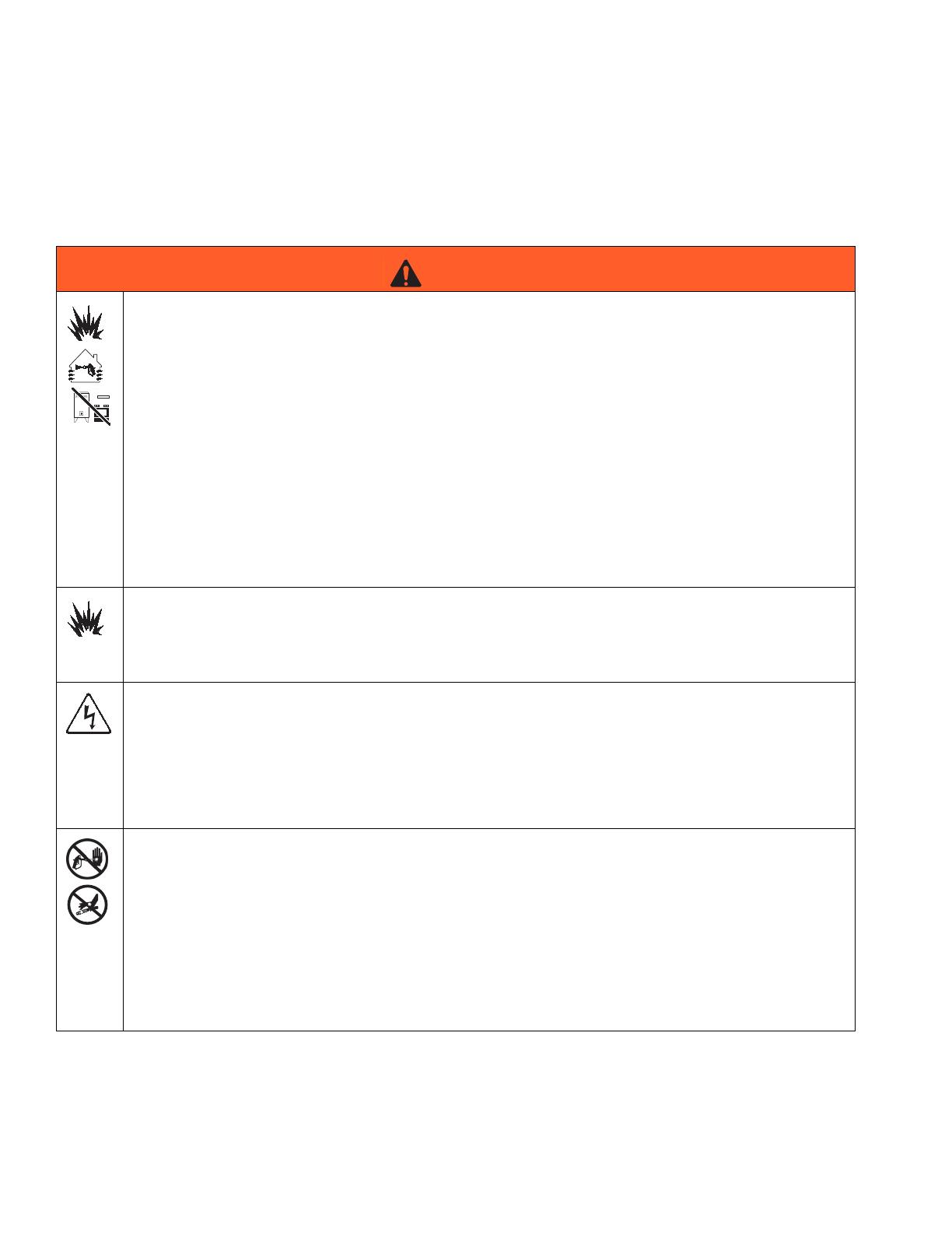
WARNING
FIRE AND EXPLOSION HAZARD
Flammable fumes, such as solvent and paint fumes, in work area can ignite or explode. To help prevent
fire and explosion:
• Use equipment only in well ventilated area.
• Eliminate all ignition sources; such as pilot lights, cigarettes, portable electric lamps, and plastic drop
cloths (potential static arc).
• Keep work area free of debris, including solvent, rags and gasoline.
• Do not plug or unplug power cords, or turn power or light switches on or off when flammable fumes
are present.
• Ground all equipment in the work area.
• Use only grounded hoses.
• Hold gun firmly to side of grounded pail when triggering into pail.
• If there is static sparking or you feel a shock, stop operation immediately. Do not use equipment
until you identify and correct the problem.
• Keep a working fire extinguisher in the work area.
SPECIAL CONDITIONS FOR SAFE USE
• To prevent the risk of electrostatic sparking, the equipment’s non-metallic parts must be cleaned
with only a damp cloth.
• Refer to the Viscon HP Heater manual for special conditions for safe use.
ELECTRIC SHOCK HAZARD
Improper grounding, setup, or usage of the system can cause electric shock.
• Turn off and disconnect power at main switch before disconnecting any cables and before servicing
equipment.
• Connect only to grounded power source.
• All electrical wiring must be done by a qualified electrician and comply with all local codes and
regulations.
SKIN INJECTION HAZARD
High-pressure fluid from gun, hose leaks, or ruptured components will pierce skin. This may look like just
a cut, but it is a serious injury that can result in amputation. Get immediate surgical treatment.
• Do not point gun at anyone or at any part of the body.
• Do not put your hand over the spray tip.
• Do not stop or deflect leaks with your hand, body, glove, or rag.
• Do not spray without tip guard and trigger guard installed.
• Engage trigger lock when not spraying.
•Follow Pressure Relief Procedure in this manual, when you stop spraying and before cleaning,
checking, or servicing equipment.
Warnings
313292G 5
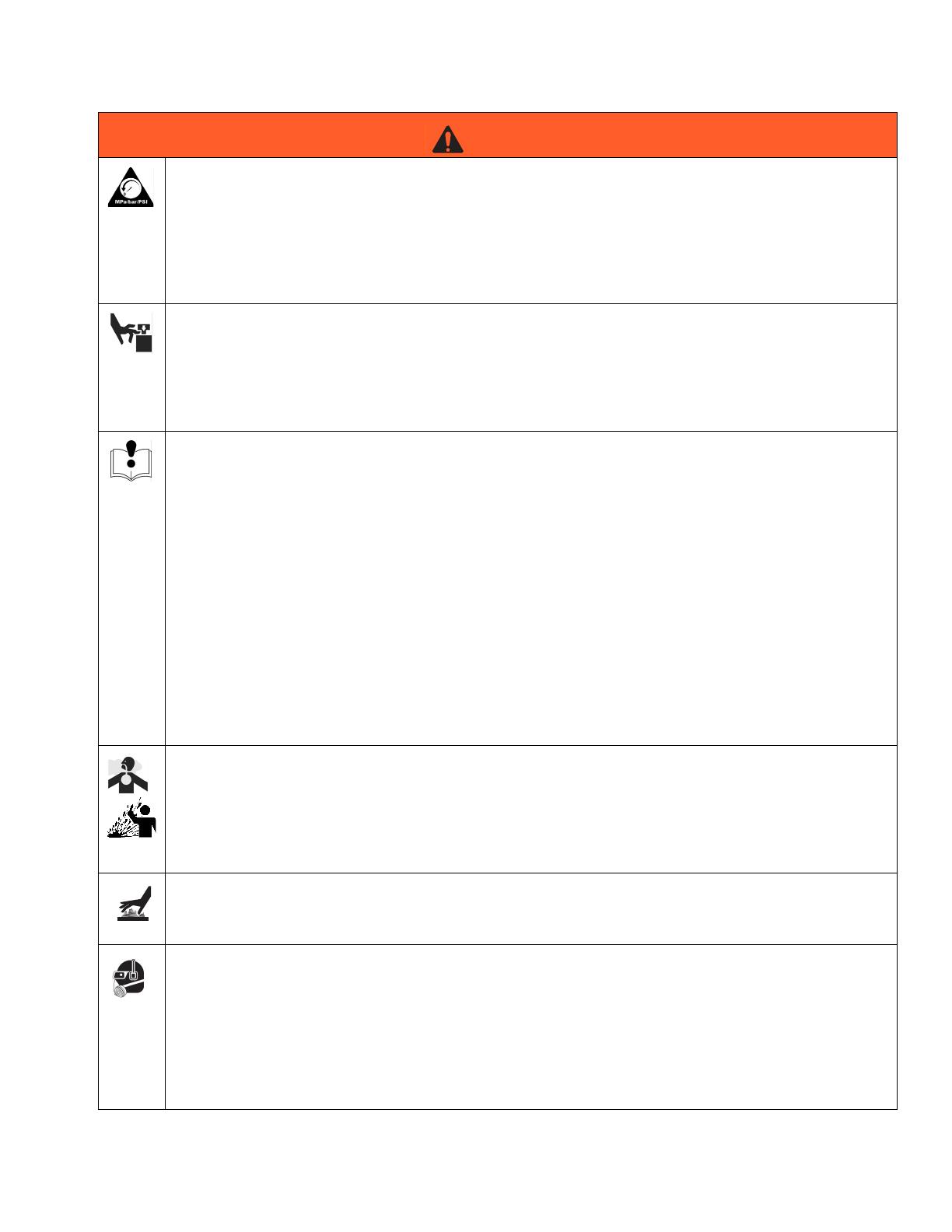
PRESSURIZED EQUIPMENT HAZARD
Fluid from the gun/dispense valve, leaks, or ruptured components can splash in the eyes or on skin and
cause serious injury.
•Follow Pressure Relief Procedure in this manual, when you stop spraying and before cleaning,
checking, or servicing equipment.
• Tighten all fluid connections before operating the equipment.
• Check hoses, tubes, and couplings daily. Replace worn or damaged parts immediately.
MOVING PARTS HAZARD
Moving parts can pinch or amputate fingers and other body parts.
• Keep clear of moving parts.
• Do not operate equipment with protective guards or covers removed.
• Pressurized equipment can start without warning. Before checking, moving, or servicing equipment,
follow the Pressure Relief Procedure in this manual. Disconnect power or air supply.
EQUIPMENT MISUSE HAZARD
Misuse can cause death or serious injury.
• Do not operate the unit when fatigued or under the influence of drugs or alcohol.
• Do not exceed the maximum working pressure or temperature rating of the lowest rated system
component. See Technical Data in all equipment manuals.
• Use fluids and solvents that are compatible with equipment wetted parts. See Technical Data in all
equipment manuals. Read fluid and solvent manufacturer’s warnings. For complete information
about your material, request MSDS forms from distributor or retailer.
• Check equipment daily. Repair or replace worn or damaged parts immediately with genuine manu-
facturer’s replacement parts only.
• Do not alter or modify equipment.
• Use equipment only for its intended purpose. Call your distributor for information.
• Route hoses and cables away from traffic areas, sharp edges, moving parts, and hot surfaces.
• Do not kink or over bend hoses or use hoses to pull equipment.
• Keep children and animals away from work area.
• Comply with all applicable safety regulations.
TOXIC FLUID OR FUMES HAZARD
Toxic fluids or fumes can cause serious injury or death if splashed in the eyes or on skin, inhaled, or
swallowed.
• Read MSDS’s to know the specific hazards of the fluids you are using.
• Store hazardous fluid in approved containers, and dispose of it according to applicable guidelines.
• Always wear impervious gloves when spraying or cleaning equipment.
BURN HAZARD
Equipment surfaces and fluid that’s heated can become very hot during operation. To avoid severe
burns, do not touch hot fluid or equipment. Wait until equipment/fluid has cooled completely.
PERSONAL PROTECTIVE EQUIPMENT
You must wear appropriate protective equipment when operating, servicing, or when in the operating
area of the equipment to help protect you from serious injury, including eye injury, inhalation of toxic
fumes, burns, and hearing loss. This equipment includes but is not limited to:
• Protective eyewear
• Clothing and respirator as recommended by the fluid and solvent manufacturer
•Gloves
• Hearing protection
WARNING
Models
6 313292G
Models
Use the following matrix to define the construction of the sprayer, based on the six digits. For example, Part XMEA00
represents an XM Plural-Component OEM sprayer (XM); 5200 psi pump set with pump filters (E); wall power supply
that is not approved for hazardous areas (A).
NOTE:
To order replacement parts, see Parts section the XM Plural-Component Sprayer Repair-Parts manual 313289. The
digits in the matrix do not correspond to the Ref. Nos. in the Parts drawings and lists.
NOTE:
See Accessories and Kits, page 25, for a list of avail-
able accessories and kits.
XM OEM sprayers are not approved for use in hazard-
ous locations.
XM E A
00
First and Second
Digits
Third Digit Fourth Digit
Fifth and Sixth
Digits
System Choice
(See Table 1 for lower models) Control Box Choice
Pump Set
(hose/gun) Pump Filters
Remote
Manifold Control Box Always 00
XM
(OEM plural com-
ponent sprayer
without a frame)
A no pumps A Wall Power Supply
B no pumps
✔
D Alternator
E 5200 psi
✔
F 5200 psi
G 6300 psi
✔
H 6300 psi
Code
System Pressure
(MPa, bar)
Pump
Filters
A Lower
(see manual 311762)
B Lower
(see manual 311762)
E 5200 psi (35, 350)
✔
L250C4 L220C4
F 5200 psi (35, 350) L250C3 L220C3
G 6300 psi (49, 490)
✔
L180C4 L145C4
H 6300 psi (49, 490) L180C3 L145C3
Table 1: Lower Models and Corresponding Identification Codes
Overview
313292G 7
Overview
Usage
XM plural-component sprayers can mix and spray most
two-component epoxy and urethane protective coatings.
When using quick-setting materials (less than 10 minute
pot life) a remote mix manifold must be used.
XM plural-component sprayers are operated via user
interface, air controls, and fluid controls.
Isocyanate Hazard
Material Self-Ignition
Moisture Sensitivity of
Isocyanates
Isocyanates (ISO) are catalysts used in two component
urethane coatings. ISO will react with moisture (such as
humidity) to form small, hard, abrasive crystals, which
become suspended in the fluid. Eventually a film will
form on the surface and the ISO will begin to gel,
increasing in viscosity. If used, this partially cured ISO
will reduce performance and the life of all wetted parts.
NOTE:
The amount of film formation and rate of crystallization
varies depending on the blend of ISO, the humidity, and
the temperature.
To prevent exposing ISO to moisture:
• Always use a sealed container with a desiccant
dryer in the vent, or a nitrogen atmosphere. Never
store ISO in an open container.
• Use moisture-proof hoses specifically designed for
ISO, such as those supplied with your system.
• Never use reclaimed solvents, which may contain
moisture. Always keep solvent containers closed
when not in use.
• Never use solvent on one side if it has been con-
taminated from the other side.
• Always park pumps when you shutdown.
• Always lubricate threaded parts with Part 217374
ISO pump oil or grease when reassembling.
XM OEM sprayers are not approved for use in hazard-
ous locations.
Spraying materials containing isocyanates creates
potentially harmful mists, vapors, and atomized partic-
ulates.
Read material manufacturer’s warnings and material
MSDS to know specific hazards and precautions
related to isocyanates.
Prevent inhalation of isocyanate mists, vapors, and
atomized particulates by providing sufficient ventila-
tion in the work area. If sufficient ventilation is not
available, a supplied-air respirator is required for
everyone in the work area.
To prevent contact with isocyanates, appropriate per-
sonal protective equipment, including chemically
impermeable gloves, boots, aprons, and goggles, is
also required for everyone in the work area.
Some materials may become self-igniting if applied
too thick. Read material manufacturer’s warnings and
material MSDS.

Location
8 313292G
Components A and B
IMPORTANT!
Material suppliers can vary in how they refer to plural
component materials.
Be aware that in this manual:
Component A
refers to resin or major volume.
Component B
refers to the hardener or minor volume.
NOTE:
This equipment doses the B component into the A com-
ponent flow. An integration hose must always be used
after the mix manifold and before the static mixer.
NOTE:
Please follow these recommendations for setup:
• use at least a 3/8 in. (10 mm) x 25 ft. (7 m) hose as
the integration hose.
• install a 24-element static mix tube after the integra-
tion hose.
Keep Components A and B Separate
Changing Materials
• When changing materials, flush the equipment mul-
tiple times to ensure it is thoroughly clean.
• Always clean the fluid inlet strainers and outlet filter
after flushing, Flush Mixed Material, page 16.
• Check with your material manufacturer for chemical
compatibility.
• Epoxies often have amines on the B (hardener)
side. Polyureas often have amines on the A (resin)
side.
NOTE:
If the amine will switch between the two sides, see
Flush Mixed Material, page 16.
Location
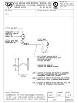
Grounding
Ground control box (ground wire attached) and both air
motors to a true earth ground.
NOTE:
If wall power is used, ground electrical connection prop-
erly according to local codes.
NOTICE
To prevent cross-contamination of the equipment’s wet-
ted parts, never interchange component A (resin) and
component B (hardener) parts.
XM OEM sprayers are not approved for use in hazard-
ous locations.
Air Motor
Ground Wire
Control Box
Ground Nut
Control Box
Ground Wire
Component Identification
313292G 9
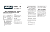
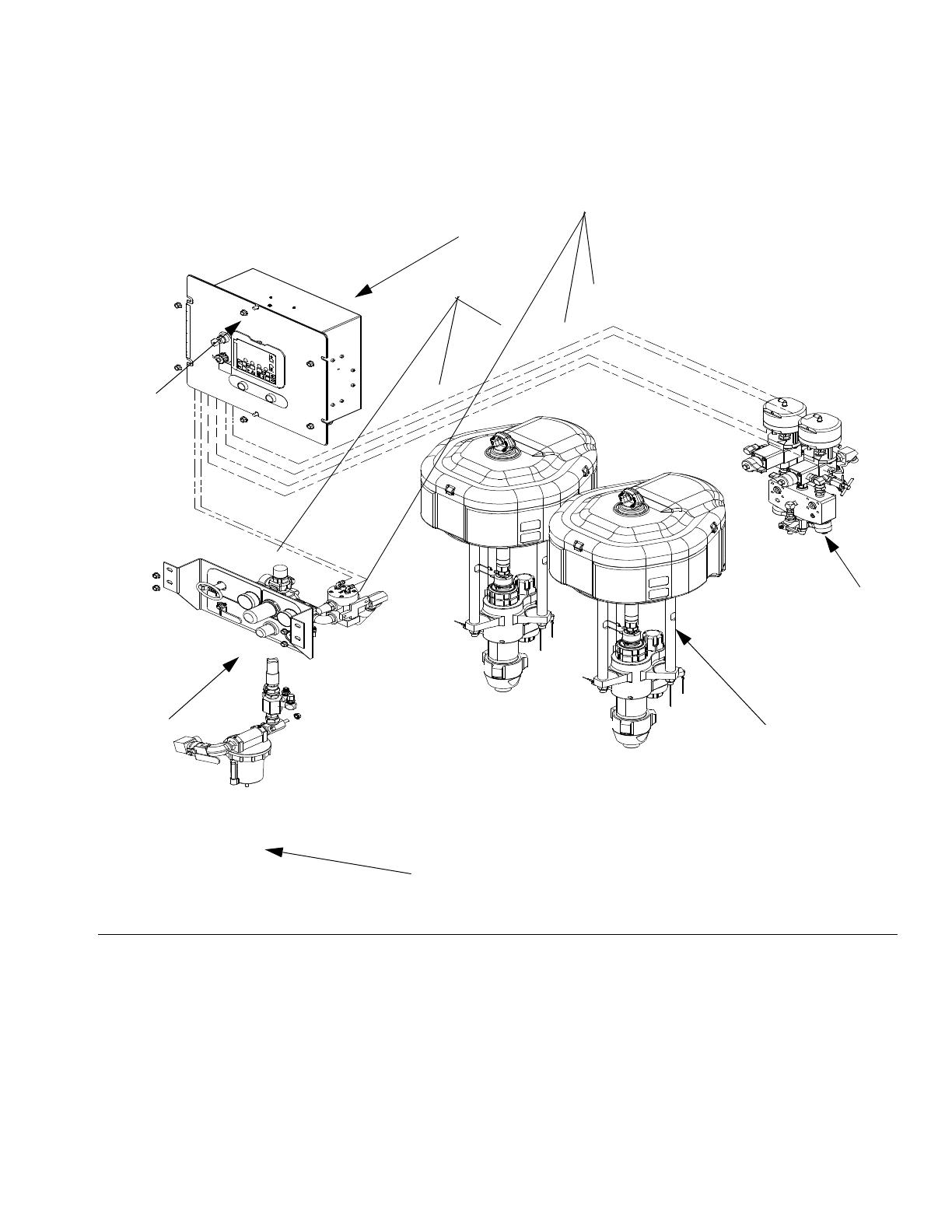
Component Identification
Key:
A Pump Assembly
B Fluid Control Assembly (see Fluid Control Assembly,
page 10)
C Control Box
D User Interface Display (see User Interface Display, page
13)
E Air Controls (see Air Controls, page 11)
F Air Inlet Manifold Assembly
68 Air Line
69 Air Line
F
IG
. 1: Typical OEM Sprayer Components
A
B
C
F
E
D
00 313292 2
68
69
Component Identification
10 313292G
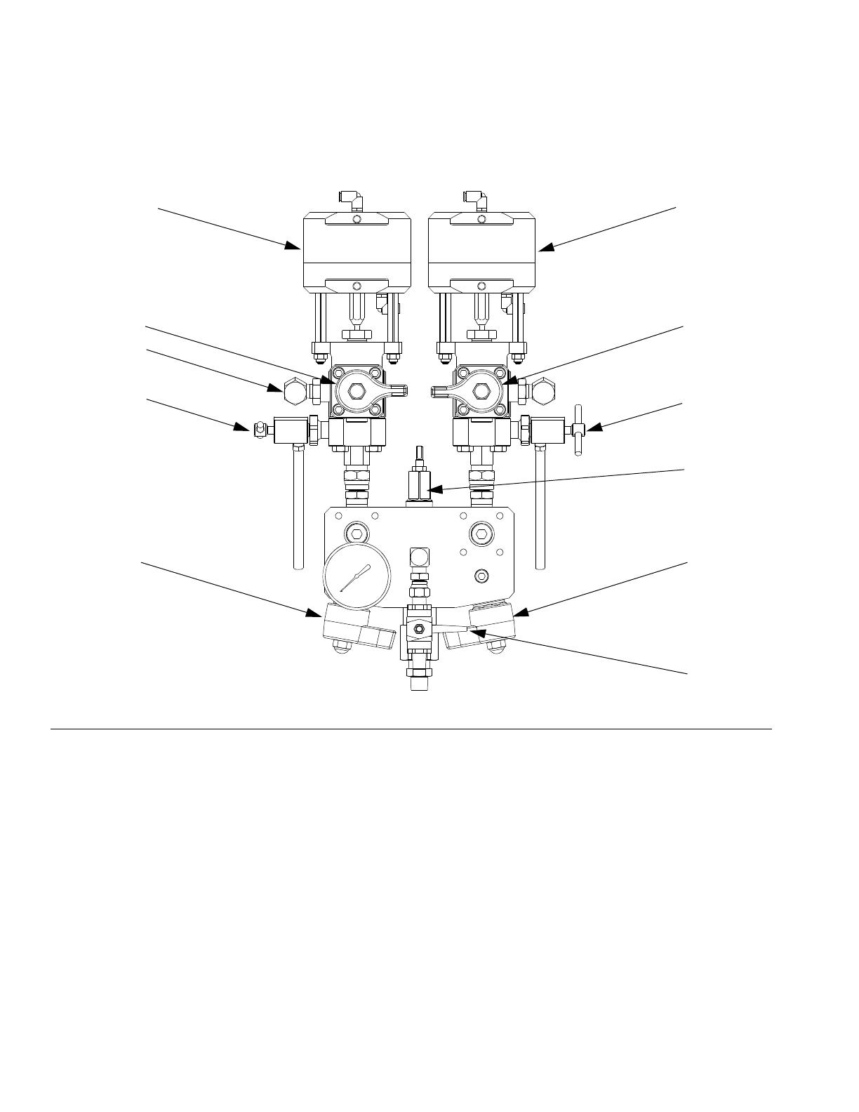
Fluid Control Assembly
AA Dosing Valve A
AB Dosing Valve B
AC Recirculation Valve A
AD Recirculation Valve B
AE Sampling Valve A
AF Sampling Valve B
AG Restriction Valve
AH Mix Manifold Shutoff / Check Valve A
AJ Mix Manifold Shutoff / Check Valve B
AK Solvent Shutoff Valve
AL Pressure Sensor (hidden)
F
IG
. 2: Fluid Control Assembly
AB
AD
AF
AG
AJ
AK
AA
AC
AE
AH
AL
r_XM1A00_312359_313289_18A
Component Identification
313292G 11
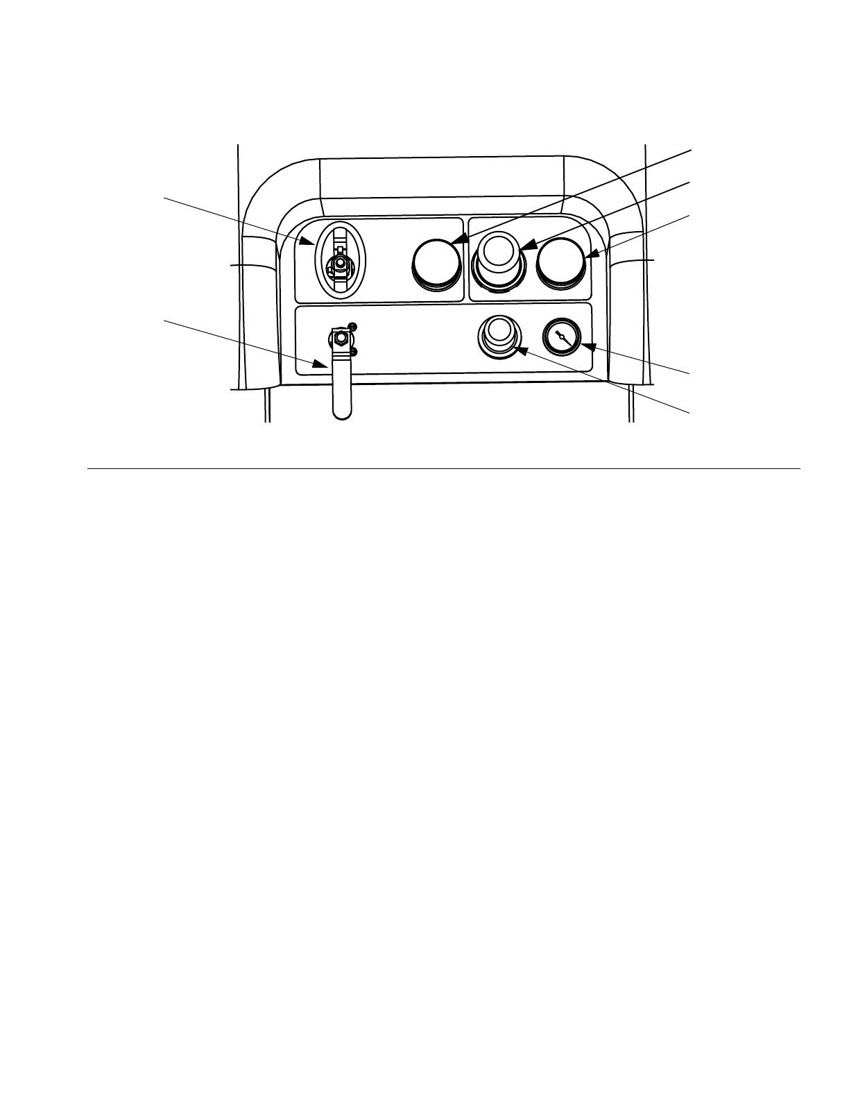
Air Controls
CA Main Pump and Air On/Off Control
CB Solvent Pump Air On/Off Control
CC Inlet Air Pressure Gauge
CD Main Pump Air Regulator
CE Main Pump Air Regulator Gauge
CF Solvent Pump Air Gauge
CG Solvent Pump Air Regulator
F
IG
. 3: Air Controls
CA
CB
CC
CD
CE
CG
CF
r_XM1A00_312359_313289_14A

Component Identification
12 313292G
User Interface
Buttons LEDs
There are four types of LEDs on the display.
F
IG
. 4: User Interface
DA
DB
DD
DE
DF
DG
DH
DK
DP
DN
DM
DC
ti13365a
DR
DJ
Call
out Button Function
DA Display
Screen
Use to view GCA display. Ratio, Mode
Selection, Error Conditions, Totalizers,
System Information.
DB Start Initiates Active Run Mode function cur-
rently selected in Run Screen.
DC Stop Terminates Active Run Mode function
currently selected.
DD Enter Press to open drop-down fields, selection
options, and save values.
DE Alarm
Reset
Resets alarms and advisories.
DF Left/Right Move between screens in run or setup
modes.
DG Function Activates mode or action represented by
the icon above each of the four buttons in
the LCD.
DH Up/Down Move between selection boxes,
drop-down fields, and selectable values
within Setup screens.
DJ Setup Key
Lock
Change ratio or enter Setup mode.
DR USB Port Connection for data download. Use only
in non-hazardous areas.
Call
out LED Function
DK Blue Dosing valve active
•
on - dosing valve is active
•
off - dosing valve is not active
DM Green Spray mode active
•
selected mode is on (active)
•
selected mode is off (inactive)
DN Red Alarm
•
on - alarm is present
•
off - no alarm
DP Yellow Warning
•
on - is active.
•
off - no warning indicated. Ratio
and setup fields are not change-
able.
•
flashing - key is present and
turned. Ratio and setup fields
are changeable.

Component Identification
313292G 13
User Interface Display
NOTE:
For details regarding the user interface display see the
XM Plural-Component Sprayer operation manual
312359.
Main Display Screen Components
The following figure calls out the navigational, status, and general informational components of each display screen.
F
IG
. 5: Main Display Screen Components
Current Date and Time
Navigate to screens
within same group
Go back one screen
Current Status Bar
Navigational Bar
Function Display
Remaining Potlife Time

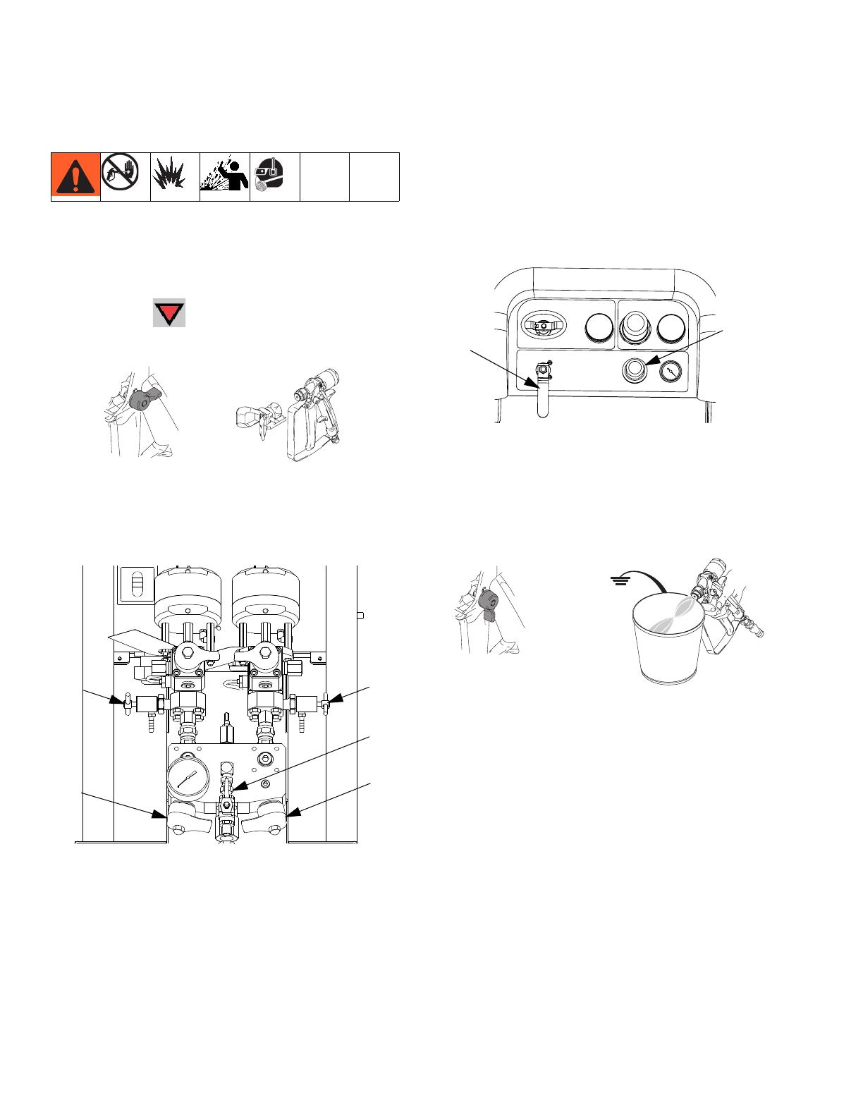
Pressure Relief Procedure
14 313292G
Pressure Relief Procedure
Relieve A and B Fluid Pressure
1. Engage trigger lock.
2. Press Stop .
3. If fluid heaters are used, shut them off.
.
4. Shut off feed pumps, if used.
5. Remove spray tip and clean.
6. Disengage trigger lock.
7. Hold a metal part of the gun firmly to a grounded
metal pail with a splash guard in place. Trigger gun
to relieve pressure in material hoses.
8. Engage trigger lock.
Relieve Pump Fluid Pressure and Flush Mix
Hose
9. Close mix manifold valves (AH, AJ), then open sol-
vent flush valve (AK) on mix manifold.
10. Open solvent flush ball valve (CB). Use lowest pres-
sure needed to flush material out of hose.
11. Disengage trigger lock.
Follow Flush Mixed Material procedure prior to
relieving pressure.
Follow Pressure Relief Procedure when you stop
spraying or dispensing; and before cleaning, check-
ing, servicing, or transporting equipment.
ti1949a
ti1950a
ti1953a
ti1949a
AK
AJ
AH
CB
ti1950a
Pressure Relief Procedure
313292G 15
12. Hold a metal part of the gun firmly to a grounded
metal pail with a splash guard in place. Trigger gun
to flush mixed material out of line with clean solvent.
13. Shut off solvent pump air control valve (CB).
14. Repeat steps 11 and 12. Then continue to step 15.
15. Close solvent flush valve (AK) on mix manifold.
16. Release any residual gun pressure and engage trig-
ger lock.
AK
ti1949a
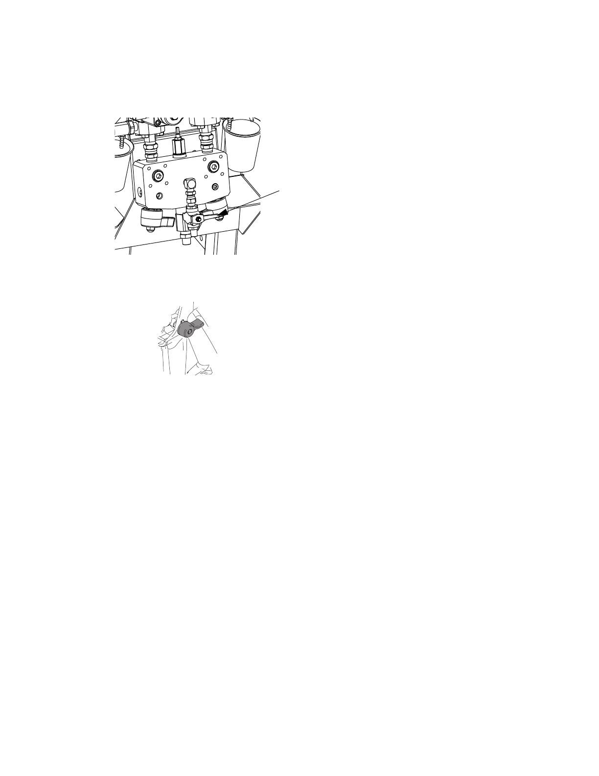
Flush Mixed Material
16 313292G
Flush Mixed Material
Flush Mix Manifold
Use Solvent Pump
1. Press Stop to turn off system. Engage trigger
lock. Remove spray tip.
2. Ensure sampling valves (AE, AF) and mix manifold
valves (AH, AJ) are closed.
3. Open solvent shutoff valve (AK) at mix manifold.
4. Open solvent pump air valve (CB). Pull out and
slowly turn solvent pump air regulator (CG) clock-
wise to increase air pressure. Use lowest possible
pressure.
.
5. Disengage trigger lock and trigger gun into a
grounded pail. Use a pail lid with a hole to dispense
through. Seal around hole and gun with a rag to pre-
vent splash back. Be careful to keep fingers away
from front of gun. Flush out mixed material until
clean solvent dispenses.
ti1949a
ti1948a
AE
AF
AJ
AH
AK
CG
CB
ti1950a
ti1953a
Flush Mixed Material
313292G 17
6. Close solvent pump air valve (CB) and solvent shut-
off valve (AK) at mix manifold. Trigger spray gun to
relieve pressure.
7. Engage trigger lock.
8. Disassemble and clean spray tip with solvent by
hand. Reinstall on gun.
AK
ti1949a
Installation and Setup
18 313292G
Installation and Setup
NOTE:
See , page 27, to aid in component installation.
Connect Air Lines
Refer to component identification in F
IG
. 1, page 9.
Refer to the pneumatic schematic drawings in the XM
Plural-Component Sprayer repair-parts manual 313289
for guidance.
• Connect air lines (68, 69) between the fluid control
assembly (B) and the control box (C).
• Connect air lines (68, 69) between the air controls
assembly (E) and the control box.
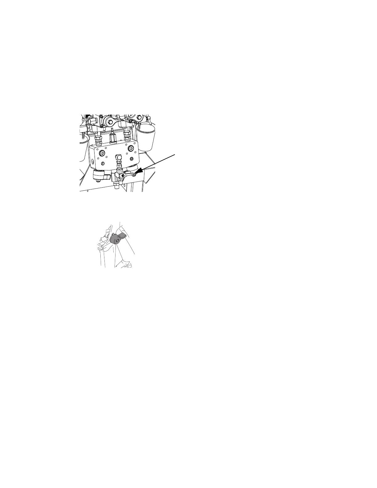
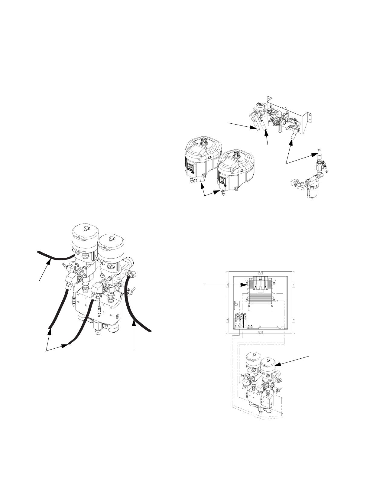
Connect Fluid Hoses
Use the following illustration as a guide to connect the
fluid hoses.
Connect Air Hoses
• Connect air hose (12) between air inlet manifold and
air controls assembly. (Hose called out as 12(C)).
• Connect air hose (12) between air controls assem-
bly and both air motors. (Hose called out has 12(A)
and 12 (B)).
Connect Sensor Cables
Connect pressure and temperature sensor cables (sup-
plied with fluid control assembly (B)) to the fluid control
module.
Recirculation
Hose (gray)
Hose to Pump
Lower (black)
Recirculation
Hose (gray)
12 (A and B)
12(C)
12(B)
12(A)
r_xmaa00_313292_4a
B
Fluid
Control
Module

Operation
313292G 19
Operation
For operation instructions, see XM Plural-Component
Sprayer Operation manual 312359.
Repair
For maintenance, troubleshooting, and repair instruc-
tions, see XM Plural-Component Sprayer Repair-Parts
manual 313289.
Schematics
See XM Plural-Component Sprayer Repair-Parts man-
ual 313289 for all electrical schematics.
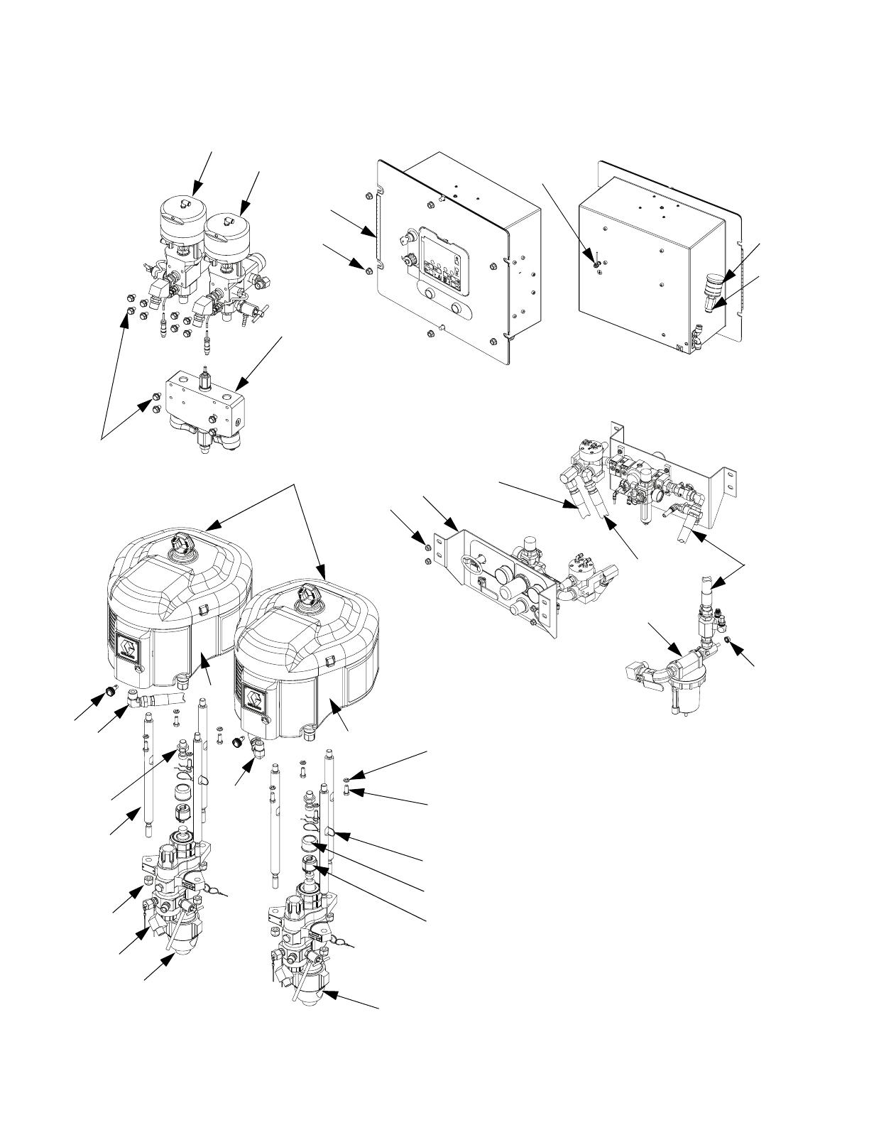
Parts
20 313292G
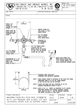
Parts
3
4
38
7
65
2
38
5
38
12
12
6
66
67
15
73
8
9
33
30
32
12
14
12
10
36
37
34
35
17
31
11
12
1
(FRONT VIEW)
(REAR VIEW)
(FRONT VIEW)
(REAR VIEW)
/