Page is loading ...

Repair-Parts
XM Plural-Component
Sprayers
For spraying two-component epoxy and urethane protective coatings in hazardous and
non-hazardous locations. For professional use only.
Important Safety Instructions
Read all warnings and instructions in this
manual. Save these instructions.
See pages 7 and 8 for model information and
agency approvals.
See page 85 for maximum working pressure.
ti21272a
313289S
EN

2 313289S
Contents
Related Manuals . . . . . . . . . . . . . . . . . . . . . . . . . . . 3
Warnings . . . . . . . . . . . . . . . . . . . . . . . . . . . . . . . . . 4
Models . . . . . . . . . . . . . . . . . . . . . . . . . . . . . . . . . . . 7
Overview . . . . . . . . . . . . . . . . . . . . . . . . . . . . . . . . . . 9
Isocyanate Hazard . . . . . . . . . . . . . . . . . . . . . . . 9
Material Self-Ignition . . . . . . . . . . . . . . . . . . . . . . 9
Moisture Sensitivity of Isocyanates . . . . . . . . . . . 9
Components A and B . . . . . . . . . . . . . . . . . . . . 10
Changing Materials . . . . . . . . . . . . . . . . . . . . . . 10
Before Repair . . . . . . . . . . . . . . . . . . . . . . . . . . . . . 11
Location . . . . . . . . . . . . . . . . . . . . . . . . . . . . . . 11
Grounding . . . . . . . . . . . . . . . . . . . . . . . . . . . . . 11
Proper Lifting of Sprayer . . . . . . . . . . . . . . . . . . 11
Pressure Relief Procedure . . . . . . . . . . . . . . . . 12
Flush Before Using Equipment . . . . . . . . . . . . . 13
Flush . . . . . . . . . . . . . . . . . . . . . . . . . . . . . . . . . . . . 14
Flush Mixed Material . . . . . . . . . . . . . . . . . . . . . 14
Empty and Flush Entire System (new sprayer or end
of job) . . . . . . . . . . . . . . . . . . . . . . . . . . . . . 16
Shutdown Entire System . . . . . . . . . . . . . . . . . . . 18
Cleaning Procedure . . . . . . . . . . . . . . . . . . . . . . . . 18
XM Setup and Troubleshooting Guide . . . . . . . . 19
Troubleshooting . . . . . . . . . . . . . . . . . . . . . . . . . . 20
Alarms . . . . . . . . . . . . . . . . . . . . . . . . . . . . . . . . . . 23
View Alarms . . . . . . . . . . . . . . . . . . . . . . . . . . . 23
Diagnose Alarms . . . . . . . . . . . . . . . . . . . . . . . . 23
Clear Alarms . . . . . . . . . . . . . . . . . . . . . . . . . . . 23
Repair . . . . . . . . . . . . . . . . . . . . . . . . . . . . . . . . . . . 31
Replace Air Filter Element . . . . . . . . . . . . . . . . 31
User Interface/Control Box . . . . . . . . . . . . . . . . 32
Air Controls . . . . . . . . . . . . . . . . . . . . . . . . . . . . 40
Fluid Control Assembly . . . . . . . . . . . . . . . . . . . 42
Sensors . . . . . . . . . . . . . . . . . . . . . . . . . . . . . . . 43
Pump Assembly . . . . . . . . . . . . . . . . . . . . . . . . 44
Solvent Pump . . . . . . . . . . . . . . . . . . . . . . . . . . 46
Fluid Heaters . . . . . . . . . . . . . . . . . . . . . . . . . . . 46
Electrical Schematics . . . . . . . . . . . . . . . . . . . . . . 47
Simplified Electrical Schematic, XM Sprayer with
Alternator . . . . . . . . . . . . . . . . . . . . . . . . . . 47
Detailed Electrical Schematic, XM Sprayer with
Alternator (page 1) . . . . . . . . . . . . . . . . . . . 49
Simplified Electrical Schematic, XM Sprayer with
Wall Power . . . . . . . . . . . . . . . . . . . . . . . . . 51
Detailed Electrical Schematic, XM Sprayer with Wall
Power (page 1) . . . . . . . . . . . . . . . . . . . . . . 53
Junction Box Wiring Schematics . . . . . . . . . . . . . 55
Fluid Heaters . . . . . . . . . . . . . . . . . . . . . . . . . . . 55
Hopper Heaters . . . . . . . . . . . . . . . . . . . . . . . . . 56
Parts . . . . . . . . . . . . . . . . . . . . . . . . . . . . . . . . . . . . 58
Control Box (255771) Parts . . . . . . . . . . . . . . . . 70
Junction Box (256540) Parts . . . . . . . . . . . . . . . 75
Fluid Control Assembly Parts . . . . . . . . . . . . . . 76
Air Inlet Manifold (255762) Parts . . . . . . . . . . . . 77
Accessories and Kits . . . . . . . . . . . . . . . . . . . . . . . 80
Dimensions . . . . . . . . . . . . . . . . . . . . . . . . . . . . . . . 82
Technical Data . . . . . . . . . . . . . . . . . . . . . . . . . . . . 85
Graco Standard Warranty . . . . . . . . . . . . . . . . . . . 86
Graco Information . . . . . . . . . . . . . . . . . . . . . . . . . 86

Related Manuals
313289S 3
Related Manuals
Manuals are available at www.graco.com.
Component Manuals in U.S. English:
Manual Description
312359
XM Plural-Component Sprayers
Operation
313292
XM Plural-Component OEM Sprayers
Instructions-Parts
311762
Xtreme
®
Displacement Pumps
Instructions-Parts
311238
NXT
™
Air Motor Instructions-Parts
312747
Double Wall Hopper Kit
Instructions-Parts
309524
Viscon
®
HP Heater Instructions-Parts
312145
XTR
™
5 and XTR
™
7 Spray Guns
Instructions-Parts
312769
Feed Pump and Agitator Kits
Instructions-Parts
312794
Merkur
®
Pump Assembly
Instructions-Parts
406699
7-Gallon Hopper Installation Kit
Instructions-Parts
406739 Desiccant Kit Instructions-Parts
406690 Caster Kit Instructions-Parts
406691 Hose Rack Kit Instructions-Parts
313258
Electric Heated Hose Power Supply Kit
Instructions-Parts
313259
Hopper or Hose Heat Circulation Kit
Instructions-Parts
312770
Lower Strainer and Valve Kit
Instructions-Parts
312749
XM Mix Manifold Kit
Instructions-Parts
313293
Alternator Conversion Kits
Instructions-Parts
313342
Dosing Valve Repair Kit
Instructions-Parts
313343
High Flow Severe Duty Shutoff Check
Valve Repair Kit Instructions-Parts

Warnings
4 313289S
Warnings
The following warnings are for the setup, use, grounding, maintenance, and repair of this equipment. The exclama-
tion point symbol alerts you to a general warning and the hazard symbol refers to procedure-specific risk. Refer back
to these warnings. Additional, product-specific warnings may be found throughout the body of this manual where
applicable.
WARNINGWARNINGWARNING
WARNING
FIRE AND EXPLOSION HAZARD
Flammable fumes, such as solvent and paint fumes, in work area can ignite or explode. To help prevent
fire and explosion:
• Use equipment only in well ventilated area.
• Eliminate all ignition sources; such as pilot lights, cigarettes, portable electric lamps, and plastic drop
cloths (potential static arc).
• Keep work area free of debris, including solvent, rags and gasoline.
• Do not plug or unplug power cords, or turn power or light switches on or off when flammable fumes
are present.
• Ground all equipment in the work area. See Grounding instructions.
• Use only grounded hoses.
• Hold gun firmly to side of grounded pail when triggering into pail.
• If there is static sparking or you feel a shock, stop operation immediately. Do not use equipment
until you identify and correct the problem.
• Keep a working fire extinguisher in the work area.
• Do not connect USB device in explosive atmospheres.
SPECIAL CONDITIONS FOR SAFE USE
• To prevent the risk of electrostatic sparking, the equipment’s non-metallic parts must be cleaned
with only a damp cloth.
• Refer to the Viscon HP Heater manual for special conditions for safe use.
ELECTRIC SHOCK HAZARD
Improper grounding, setup, or usage of the system can cause electric shock.
• Turn off and disconnect power at main switch before disconnecting any cables and before servicing
equipment.
• Connect only to grounded power source.
• All electrical wiring must be done by a qualified electrician and comply with all local codes and
regulations.

Warnings
313289S 5
INTRINSIC SAFETY
Intrinsically safe equipment that is installed improperly or connected to non-intrinsically safe equipment
will create a hazardous condition and can cause fire, explosion, or electric shock. Follow local regula-
tions and the following safety requirements.
• Only models with model number XM_D_ _ or XM_E_ _, and packaged models with part numbers
ending in 00-13, 17-23, 27-29, 31, utilizing the air-driven alternator are approved for installation in a
Hazardous (explosive atmosphere) Location - see Approvals:, page 8. Only the models stated
above meet all local safety fire codes including NFPA 33, NEC 500 and 516, and OSHA 1910.107.
To help prevent fire and explosion:
• Do not install equipment approved only for a non-hazardous location in a hazardous location.
See model ID label for intrinsic safety rating of your model.
• Do not substitute system components as this may impair intrinsic safety.
• Equipment that comes in contact with the intrinsically safe terminals must be rated for Intrinsic
Safety. This includes DC voltage meters, ohmmeters, cables, and connections. Remove the unit
from the hazardous area when troubleshooting.
• Do not connect, download, or remove USB device unless unit is removed from the hazardous
(explosive atmosphere) location.
• If explosion-proof heaters are used, ensure wiring, wiring connections, switches, and electrical distri-
bution panel all meet flame-proof (explosion-proof) requirements.
SKIN INJECTION HAZARD
High-pressure fluid from gun, hose leaks, or ruptured components will pierce skin. This may look like just
a cut, but it is a serious injury that can result in amputation. Get immediate surgical treatment.
• Do not point gun at anyone or at any part of the body.
• Do not put your hand over the spray tip.
• Do not stop or deflect leaks with your hand, body, glove, or rag.
• Do not spray without tip guard and trigger guard installed.
• Engage trigger lock when not spraying.
•Follow Pressure Relief Procedure in this manual, when you stop spraying and before cleaning,
checking, or servicing equipment.
PRESSURIZED EQUIPMENT HAZARD
Fluid from the gun/dispense valve, leaks, or ruptured components can splash in the eyes or on skin and
cause serious injury.
•Follow Pressure Relief Procedure in this manual, when you stop spraying and before cleaning,
checking, or servicing equipment.
• Tighten all fluid connections before operating the equipment.
• Check hoses, tubes, and couplings daily. Replace worn or damaged parts immediately.
MOVING PARTS HAZARD
Moving parts can pinch or amputate fingers and other body parts.
• Keep clear of moving parts.
• Do not operate equipment with protective guards or covers removed.
• Pressurized equipment can start without warning. Before checking, moving, or servicing equipment,
follow the Pressure Relief Procedure in this manual. Disconnect power or air supply.
WARNING

Warnings
6 313289S
EQUIPMENT MISUSE HAZARD
Misuse can cause death or serious injury.
• Do not operate the unit when fatigued or under the influence of drugs or alcohol.
• Do not exceed the maximum working pressure or temperature rating of the lowest rated system
component. See Technical Data in all equipment manuals.
• Use fluids and solvents that are compatible with equipment wetted parts. See Technical Data in all
equipment manuals. Read fluid and solvent manufacturer’s warnings. For complete information
about your material, request MSDS forms from distributor or retailer.
• Check equipment daily. Repair or replace worn or damaged parts immediately with genuine manu-
facturer’s replacement parts only.
• Do not alter or modify equipment.
• Use equipment only for its intended purpose. Call your distributor for information.
• Route hoses and cables away from traffic areas, sharp edges, moving parts, and hot surfaces.
• Do not kink or over bend hoses or use hoses to pull equipment.
• Keep children and animals away from work area.
• Comply with all applicable safety regulations.
TOXIC FLUID OR FUMES HAZARD
Toxic fluids or fumes can cause serious injury or death if splashed in the eyes or on skin, inhaled, or
swallowed.
• Read MSDS’s to know the specific hazards of the fluids you are using.
• Store hazardous fluid in approved containers, and dispose of it according to applicable guidelines.
• Always wear impervious gloves when spraying or cleaning equipment.
BURN HAZARD
Equipment surfaces and fluid that’s heated can become very hot during operation. To avoid severe
burns, do not touch hot fluid or equipment. Wait until equipment/fluid has cooled completely.
PERSONAL PROTECTIVE EQUIPMENT
You must wear appropriate protective equipment when operating, servicing, or when in the operating
area of the equipment to help protect you from serious injury, including eye injury, inhalation of toxic
fumes, burns, and hearing loss. This equipment includes but is not limited to:
• Protective eyewear
• Clothing and respirator as recommended by the fluid and solvent manufacturer
•Gloves
• Hearing protection
WARNING

Models
313289S 7
Models
Check the identification plate (ID) for the 6-digit part number of the sprayer. Use the following matrix to define the
construction of the sprayer, based on the six digits. For example, Part XM1A00 represents an XM Plural-Component
sprayer (XM); 5200 psi pump set with pump filters (1); wall power supply, no heaters, no junction box, and is not
approved for hazardous areas (A); with no additional kits (00).
NOTE:
Some configurations in the following matrix cannot be built. Consult with distributor or Graco representative.
To order replacement parts, see Parts section in this manual. The digits in the matrix do not correspond to the Ref.
Nos. in the Parts drawings and lists.
Location Category Key:
NE Not for use in European explosive atmosphere locations or hazardous locations.
EH For use in explosive atmospheres and hazardous locations
.
XM sprayers are not approved for use in hazardous
locations unless the base model, all accessories, all
kits, and all wiring meet local, state, and national
codes.
XM 1 A
00
First and
Second
Digits
Third Digit Fourth Digit
Fifth and
Sixth
Digits
System Choice
(See Table 1 for lower models) Kit Choice
Additional
Kit
Pump Set
(hose/gun)
Pump
Filters
Remote
Manifold
Control
Box
Fluid
Heaters
Junction
Box
Location
Category
Approvals
(See page 8
for approvals)
See Table
2 for
selections
XM
(plural com-
ponent
sprayer
mounted
on a frame)
1 5200 psi
✔
A
Wall Power
Supply NE
CE, FM,
FM
c
2 5200 psi B
Wall Power
Supply
✔✔
NE CE, FM,
FM
c
3 6300 psi
✔
C
Wall Power
Supply
✔
NE CE, FM,
FM
c
4 6300 psi D
IS/
Alternator EH
CE, FM,
FM
c,
Ex
5 5200 psi
✔✔
E
IS/
Alternator
✔
EH
CE, FM,
FM
c,
Ex
6 5200 psi
✔
7 6300 psi
✔✔
8 6300 psi
✔

Models
8 313289S
Approvals:
See appropriate column on page 7
.
NOTE: See Repair and Spare Parts Reference, page 79, for more information. See Related Manuals, page 3, for
kit manual numbers.
XM _ A_ _
XM _ B_ _
XM _ C_ _
XM _ D_ _
XM _ E_ _
Code
System Pressure
(MPa, bar)
Pump
Filters
A Lower
(see manual 311762)
B Lower
(see manual 311762)
1 or 5 5200 psi (35, 350)
✔
L250C4 L220C4
2 or 6 5200 psi (35, 350) L250C3 L220C3
3 or 7 6300 psi (49, 490)
✔
L180C4 L145C4
4 or 8 6300 psi (49, 490) L180C3 L145C3
Intrinsically safe for Class I, Div 1, Group D, T2
Class I, Division 1, Group D, T2
Ta = 0°C to 54°C
FM09ATEX0015X
II 2 G
Ex d ia px IIA T2 Tamb = 0ºC to 54ºC
See Special Conditions for Safe Use in Warnings, page 4.
Table 1: Lower Models and Corresponding Identification Codes
Table 2: Additional Kits - Identification Code Index
20 Gal.
Hopper
Kit
Hopper
Heater
Kit 240V
Hopper
Fluid
Inlet Kit
Hopper
Universal
Mount Kit
Twistork
Agitator
Kit
T2 Pump
Feed Kit
(on
hopper)
5:1 Pump
Feed Kit
(on
hopper)
7 Gal.
Hopper
(Green)
and
Bracket
Kit
7 Gal.
Hopper
(Blue)
and
Bracket
Kit
Drum
Feed Kit
(Dual T2
and
Agitator)
Drum
Feed Kit
(Dual 5:1
and
Agitator)
Heated
Hopper/
Hose
Circulation
Kit
00
11 1111 1
13 11111
14 111 1 1 1
15 11 1 1 1 1
16 11 1 1 1 1
17 1111 1 1
19 11111 1
21 2222
23 2222
24 222 2 2
25 22 2 2 2
26 22 2 2 2
27 2222 1
29 2222 1
30 2
31 2
32 11

Overview
313289S 9
Overview
Isocyanate Hazard
Material Self-Ignition
Moisture Sensitivity of
Isocyanates
Isocyanates (ISO) are catalysts used in two component
foam and polyurea coatings. ISO will react with moisture
(such as humidity) to form small, hard, abrasive crystals,
which become suspended in the fluid. Eventually a film
will form on the surface and the ISO will begin to gel,
increasing in viscosity. If used, this partially cured ISO
will reduce performance and the life of all wetted parts.
NOTE:
The amount of film formation and rate of crystallization
varies depending on the blend of ISO, the humidity, and
the temperature.
To prevent exposing ISO to moisture:
• Always use a sealed container with a desiccant
dryer in the vent, or a nitrogen atmosphere. Never
store ISO in an open container.
• Keep the ISO lube pump reservoir filled with Graco
Throat Seal Liquid (TSL), Part 206995. The lubri-
cant creates a barrier between the ISO and the
atmosphere.
• Use moisture-proof hoses specifically designed for
ISO, such as those supplied with your system.
• Never use reclaimed solvents, which may contain
moisture. Always keep solvent containers closed
when not in use.
• Never use solvent on one side if it has been con-
taminated from the other side.
• Always park pumps when you shutdown.
• Always lubricate threaded parts with Part 217374
ISO pump oil or grease when reassembling.
XM sprayers are not approved for use in hazardous
locations unless the base model, all accessories, all
kits, and all wiring meet local, state, and national
codes. See Models, page 7, to determine the appro-
priate location for your particular model.
Spraying materials containing isocyanates creates
potentially harmful mists, vapors, and atomized partic-
ulates.
Read material manufacturer’s warnings and material
MSDS to know specific hazards and precautions
related to isocyanates.
Prevent inhalation of isocyanate mists, vapors, and
atomized particulates by providing sufficient ventila-
tion in the work area. If sufficient ventilation is not
available, a supplied-air respirator is required for
everyone in the work area.
To prevent contact with isocyanates, appropriate per-
sonal protective equipment, including chemically
impermeable gloves, boots, aprons, and goggles, is
also required for everyone in the work area.
Some materials may become self-igniting if applied
too thick. Read material manufacturer’s warnings and
material MSDS.

Overview
10 313289S
Components A and B
IMPORTANT!
Material suppliers can vary in how they refer to plural
component materials.
Be aware that in this manual:
Component A
refers to resin or major volume.
Component B
refers to the hardener or minor volume.
NOTE:
This equipment doses the B component into the A com-
ponent flow. An integration hose must always be used
after the mix manifold.
Follow these recommendations for reassembly and
setup:
• use at least a 3/8 in. (10 mm) x 25 ft. (7 m) hose.
• install a 24-element static mix tube after the integra-
tion hose.
Keep Components A and B Separate
Changing Materials
• When changing materials, flush the equipment mul-
tiple times to ensure it is thoroughly clean.
• Always clean the fluid inlet strainers and outlet filter
after flushing. See Flush on page 14.
• Check with your material manufacturer for chemical
compatibility.
• Epoxies often have amines on the B (hardener)
side. Polyureas often have amines on the A (resin)
side.
NOTE:
If the amine will switch between the two sides, see
Flush on page 14.
NOTICE
To prevent cross-contamination of the equipment’s
wetted parts, never interchange component A
(resin) and component B (hardener) parts.

Before Repair
313289S 11
Before Repair
Location
Grounding
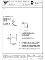
Connect ground wire clamp (FG) to a true earth ground.
If wall power is used to power controls or heaters,
ground electrical connection properly according to local
codes.
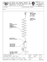
Proper Lifting of Sprayer
Lift Using a Forklift
Power must be off. Sprayer can be raised and moved
using a forklift. Carefully lift the sprayer; make sure it
balances evenly.
Lift Using a Hoist
Sprayer can also be lifted and moved using a hoist.
Connect a bridle swing, hooking an end to each of the
air motor lift rings. Hook the center ring to a hoist Care-
fully lift the sprayer; make sure it balances evenly.
XM sprayers are not approved for use in hazardous
locations unless the base model, all accessories, all
kits, and all wiring meet local, state, and national
codes. See Models, page 7, to determine the appro-
priate location for your particular model.
FG
ti21273a
Follow instructions to avoid serious injury or damage
to equipment. Never lift with the hopper(s) filled.
2.0 ft. (0.61 m)
minimum
ti21274a

Before Repair
12 313289S
Pressure Relief Procedure
Relieve A and B Fluid Pressure
1. Engage trigger lock.
2. Press .
3. If fluid heaters are used, shut them off using the
controls on the heater control box.
4. Shut off feed pumps, if used.
5. Remove spray tip and clean.
6. Disengage trigger lock.
7. Hold a metal part of the gun firmly to a grounded
metal pail with a splash guard in place. Trigger gun
to relieve pressure in material hoses.
8. Engage trigger lock.
Relieve Pump Fluid Pressure
9. Close mix manifold valves (AH, AJ), then open sol-
vent flush valve (AK) on mix manifold.
10. Open solvent pump air control (CB). Use lowest
pressure needed to flush material out of hose.
Follow Pressure Relief Procedure when you stop
spraying or dispensing; and before cleaning, check-
ing, servicing, or transporting equipment.
TI1949a
Fluid Heater A
Fluid Heater B
ti21275a
TI1950a
TI1953a
TI1949a
Replace with illustration
AH
AJ
AK
312359 313289
CB
r_312359_313289_14

Before Repair
313289S 13
11. Disengage trigger lock.
12. Hold a metal part of the gun firmly to a grounded
metal pail with a splash guard in place. Trigger gun
to flush mixed material out of line with clean solvent.
13. Shut off solvent pump on air control panel.
14. Repeat steps 11 and 12. Then continue to step 15.
15. Close solvent flush valve (AK) on mix manifold.
16. Release any residual gun pressure and engage trig-
ger lock.
Flush Before Using Equipment
The equipment was tested with lightweight oil, which is
left in the fluid passages to protect parts. To avoid con-
taminating your fluid with oil, flush the equipment with a
compatible solvent before use. See Flush on page 14.
TI1950a
Replace with illustration
AK
r_312359_313289_5
TI1949a

Flush
14 313289S
Flush
Flush Mixed Material
Flush Mix Manifold
Use Solvent Pump
1. Press to turn off system. Follow Pressure
Relief Procedure, page 12. Engage trigger lock.
Remove spray tip.
2. Close sampling valves (AE, AF) and mix manifold
valves (AH, AJ).
3. Open solvent shutoff valve (AK) at mix manifold.
4. Open solvent pump air control (CB). Pull out and
slowly turn solvent pump air regulator (CG) clock-
wise to increase air pressure. Use lowest possible
pressure.
5. Disengage trigger lock. Hold a metal part of the gun
firmly to a grounded metal pail with a splash guard
in place.Use a pail lid with a hole in it to dispense
through. Be careful to keep fingers away from the
front of the gun. Trigger gun until solvent appears.
6. Engage trigger lock.
4)!
TI1949a
TI1948a
AE
AF
AJ
AH
AK
r_xm1a00_313289_12f
CG
CB
r_312359_312359_3
TI195oa
TI1953a
TI1949a


Flush
16 313289S
Empty and Flush Entire System
(new sprayer or end of job)
NOTE:
• If system includes heaters and heated hose, turn
them off and allow to cool before flushing. Do not
turn on heaters until fluid lines are clear of sol-
vent.
• Use the lowest possible pressure when flushing to
avoid splashing.
• Before color change or shutdown for storage, flush
at a higher flow rate and for a longer time.
• To flush only mix manifold, see Flush Mix Manifold
procedure page 14.
Guidelines
Flush new systems if coating materials will be contami-
nated by 10W oil.
Flush system when any of the following situations occur.
Flushing will help prevent materials from clogging the
line between hoppers and pump inlets.
• anytime sprayer will not be used for more than
one week
• if materials used will settle
• if using thixotropic resins that require agitation
Procedure
1. Follow Pressure Relief Procedure, page 12, and
Flush Mixed Material, page 14, as required.
Engage trigger lock. Turn main pump air regulator
(CD) fully counter-clockwise to shut off.
NOTE:
When flushing coating materials remove pump fluid fil-
ters, if installed, and soak in solvent to decrease clean-
ing time. Proceed with Step 2. If flushing a new system,
leave filters in place.
2. Move circulation return lines to separate fluid con-
tainers to pump remaining fluid out of system.
3. Increase main pump air regulator (CD) pressure to
30 psi (21 kPa, 2.1 bar).
4. Select . Press .
NOTE:
When running pumps independently set to or
. Press and as needed to clean.
NOTE:
If sprayer does not start with static pressure, increase
air pressure by 10 psi (69 kPa, 0.7 bar) increments. To
avoid splashing do not exceed 40 psi (28 kPa, 2.8 bar).
air regulator
TI1949a
CD
r_312359_313289_13

Flush
313289S 17
5. Open recirculation valves (AC, AD) for respective
pump dispense side. Run pumps until the A and B
reservoirs are empty. Salvage the material in sepa-
rate, clean containers.
NOTE:
When priming or flushing the pumps, it is normal to get
cavitation or pump runaway alarms. Clear the alarms
, and press again as necessary. These
alarms prevent excessive pump speeds that can dam-
age pump packings.
6. Wipe the reservoirs clean, then add solvent to each.
Move circulation lines to waste containers.
7. Repeat Step 4 to flush through each side until clean
solvent exits recirculation hose.
8. Stop and move recirculation hoses back to reser-
voirs. Continue recirculating until machine is thor-
oughly flushed.
9. Close recirculation valves (AC, AD) and open mix
manifold valves (AH, AJ). Dispense fresh solvent
through mix manifold valves and out gun.
10. Close mix manifold valves (AH, AJ).
11. Slowly open sampling valves (AE, AF) to flush sol-
vent through until clean. Close sampling valves.
Press .
12. Follow Pressure Relief Procedure, page 12.
13. Remove pump fluid filters, if installed, and soak in
solvent. Clean and replace filter cap. Clean filter
o-rings and leave out to dry. Do not leave o-rings in
solvent.
14. Close main air valve (E).
NOTE:
Always leave some type of fluid, such as solvent or oil,
in the system to prevent scale build up. This build up
can flake off later. Do not use water.
AC
AD
r_312359_313289_6
AD
AF
AJ
AC
AE
AH
r_312359_313289_7

Shutdown Entire System
18 313289S
Shutdown Entire System
Follow this procedure before prolonged shutdown or
before servicing equipment.
1. Follow Pressure Relief Procedure, page 12. Place
gun over pail. Trigger gun; wait until pumps are
down.
2. Engage trigger lock, turn off air regulator, and close
main air shutoff valve. Remove spray tip.
3. Follow flushing procedure, see Flush on page 14.
4. Follow Pressure Relief Procedure, page 12.
Engage trigger lock.
5.
For prolonged shutdown (one week or longer):
• Follow flushing procedure, see Empty and
Flush Entire System (new sprayer or end of
job) on page 16.
• Cap fluid outlets to keep solvent in the lines.
• Fill pump A and B packing nuts with throat seal
liquid (TSL).
Cleaning Procedure
1. Ensure all equipment is grounded. See Grounding,
page 11.
2. Turn off all heaters and allow equipment to cool.
3. Flush mixed material. See Flush Mixed Material,
page 14.
4. Relieve pressure. See Pressure Relief Procedure,
page 12.
5. Shutdown sprayer and turn off all power. See Shut-
down Entire System, page 18.
6. Ensure the area where the sprayer will be cleaned
is well ventilated; and remove all ignition sources.
7. Clean external surfaces using only a rag soaked in
solvent that is compatible with the spray material
and the surfaces being cleaned.
8. Allow enough time for solvent to dry before using
sprayer.
TI1953a
TI1949a
4)!
TI1948a
TI1949a

XM Setup and Troubleshooting Guide
313289S 19
XM Setup and Troubleshooting Guide
The following setup information will help ensure the system is setup properly. See the XM repair-parts manual for trouble-
shooting and repair instructions.
Grounding
• Ground system to a true earth ground.
• Ensure incoming power is grounded.
Air Supply
• Use at least a 3/4 in. (19mm) ID air hose, no longer
than 50 feet (15m).
• Ensure the first gauge (supply) stays above 80 psi
(0.55 MPa, 5.5bar) while spraying.
• Ensure that the pump spray pressure regulator is set to
at least 35 psi (2.4 bar) for spraying.
• Ensure that the solenoid air filter/regulator behind the
air panel is set to at least 80-85 psi.
• Check that the air filter element in the solenoid air fil-
ter/regulator behind the air panel is clean.
Calibration
• Adjust the B side fluid restrictor so that the calibration
bar graph averages center to right middle. This means
that the “B” dosing valve is open 25% to 75% of the
time.
• Ensure dosing valve needle packing nuts are not
adjusted too tight. They should be snug when there is
no fluid pressure on the valve.
• If feed pumps are used, don’t use more than 250psi
(17 bar). Excess pressure adds double the amount of
pressure on only the upstroke of the XM metering
pump.
Motor Icing
Air motors accumulate ice in the exhaust valving and muf-
fler under hot and humid conditions or under cold ambient
conditions. It can cause pressure loss or motor stalling.
• The ‘B’ fluid pressure should always be 15% to 30%
higher than ‘A’ pressure.
•
A larger pressure difference indicates ‘A’ motor icing.
• A smaller or negative pressure difference indicates ‘B’
motor icing.
• Ensure that the NXT motor De-Ice bleed valves are
open to bleed warm air across the ice.
• Ensure that the motor is left active when not spraying
to keep the internal bleed air working. Leave the motor
active in Spray mode or Manual mode to keep the
bleed air on.
Restrictions or Lost Pressure
• Always use filter screens in the XM pump lowers. Filter
style pumps come with 60 mesh screens. Optional 30
mesh elements are also supplied.
• Always use a gun filter. 60 mesh is provided in the gun.
Check that the static mixer is clean.
• Early mix manifolds (2009) had a 40 mesh screen on
the B side. The screen could plug with materials that
have filled ‘B’ side fluids.
Remote Mix Manifold Applications
Ensure remote mix manifold outlet kit is installed. See XM
Repair parts manual. The kit includes outlet check valves
which isolate the pump pressure sensors from the outlet
hoses, and includes a ‘B’ side restrictor valve for the
machine outlet.
NOTE: Early remote manifold machines didn’t include
the ‘B’ restrictor valve from the factory.
• Ensure that the ‘A’ and ‘B’ outlet hose sizes volume
balanced close to the mix ratio. Unbalanced hose sizes
can cause off ratio slugs at the mix manifold during
pressure and/or flow transitions. See XM Mix Manifold
Kits manual.
• If a minimum of integration and mix hose is used,
ensure that “Fast Dosing” is selected in the setup
screens.
Software Version
• Ensure all modules in the system use software from
same token. Different software versions may not be
compatible.
• The latest software version for each system can be
found at Tech Support at www.graco.com.

Troubleshooting
20 313289S
Troubleshooting
NOTE:
The sprayer operates using air pressure. Many prob-
lems are caused by inadequate air supply. The inlet air
pressure gauge cannot drop below 50 psi (0.35 MPa,
3.5 bar) while running.
NOTE:
If an error code displays, see Alarms on page 23.
Problem Cause Solution
Display not lit on system with alternator
power supply.
No electric power.
Air valve not turned on. Turn on main air valve to system.
Air supply pressure too low. Increase pressure to 30 psi (0.21 MPa,
2.1 bar) or greater.
Air supply filters plugged. Inlet manifold
filter (604) or air regulator (344) filter
plugged.
Clean filter bowls; replace filter elements.
Page 31.
Turbine air regulator (277) set too low. Adjust to 18 +/- 1 psi (12.6 +/- 10 kPa,
1.26 +/- 0.07 bar).
Alternator turbine failure. Repair or replace turbine. Page 38.
Power supply not connected to main
board.
Check power connections to main board.
See Electrical Schematics, starting on
page 47.
Display board failure. Replace display board. Page 36.
Display not lit on system with alternator
power. Green light is present on FCM
(218) and USB (219), but no green light is
present on back of display module (204).
Faulty CAN cable (268). Or CAN cable is
disconnected.
Check cable and replace. See Alternator
Assembly, page 72.
Faulty display module. Replace display module. See User Inter-
face/Control Box, page 32.
Display not lit on system with wall power
supply. No green light present on back of
display module (204).
No electric power. Disconnect “off” or
breaker “open.”
Reset main disconnect and breaker.
No green lights present on display, FCM,
or USB module.
Check for 24 Vdc on J1, pins 2 and 3, of
power supply. See Electrical Schemat-
ics, starting on page 47. If there is not 24
Vdc, replace with 15V747.
No display power through CAN cable
(266). Green light in present on FCM
(218), but is not present on USB module
(219).
Check CAN cable. Replace if necessary.
See Wall Power Supply Assembly,
page 73.
Green light is present on USB module
(219).
Check CAN cable (274). Replace if nec-
essary. See Wall Power Supply Assem-
bly, page 73.
Display not lit on system with wall power
supply. Green light is present on back of
display module (204).
Display module failed. Replace display module. See User Inter-
face/Control Box, page 32.
/