Woods Equipment M8200 User manual
- Type
- User manual

PN-46018 (Rev. 3/15/02)
111868 LOADER MOUNTING KIT
Loaders
1020
1027
mounting to
Kubota Tractor Models
M8200
M9000
Includes
Valve Kits
56037
56038
56042
Hose Kits
40542
40547
46047
46018

ii
Introduction (2/9/01)
TO THE DEALER:
Assembly and proper installation of this product is the responsibility of the WOODS dealer. Read manual instructions
and safety rules. Make sure all items on the Dealer’s Pre-Delivery and Delivery Check Lists in the Operator’s Manual
are completed before releasing equipment to the owner.
TO THE OWNER:
Read this manual before operating your WOODS equipment. The information presented will prepare you to do a better
and safer job. Keep this manual handy for ready reference. Require all operators to read this manual carefully and
become acquainted with all the adjustment and operating procedures before attempting to operate. Replacement
manuals can be obtained from your dealer or, in the United States and Canada, by calling 1-800-319-6637.
The equipment you have purchased has been carefully engineered and manufactured to provide dependable and
satisfactory use. Like all mechanical products, it will require cleaning and upkeep. Lubricate the unit as specified.
Observe all safety information in this manual and safety decals on the equipment.
For service, your authorized WOODS dealer has trained mechanics, genuine WOODS service parts, and the
necessary tools and equipment to handle all your needs.
Use only genuine WOODS service parts. Substitute parts will void the warranty and may not meet standards required
for safe and satisfactory operation. Record the model number and serial number of your equipment in the spaces
provided:
Model: 111868 Loader Mounting Kit
Provide this information to your dealer to obtain correct repair parts.
Throughout this manual, the term IMPORTANT is used to indicate that failure to observe can cause damage to
equipment. The terms CAUTION, WARNING and DANGER are used in conjunction with the Safety-Alert Symbol, (a
triangle with an exclamation mark), to indicate the degree of hazard for items of personal safety.
This Safety-Alert Symbol indicates a hazard and means
ATTENTION! BECOME ALERT! YOUR SAFETY IS INVOLVED!
Indicates an imminently hazardous situation that, if not avoided, will
result in death or serious injury.
Indicates a potentially hazardous situation that, if not avoided,
could result in death or serious injury, and includes hazards that are
exposed when guards are removed.
Indicates a potentially hazardous situation that, if not avoided, may
result in minor or moderate injury.
Indicates that failure to observe can cause damage to equipment.
NOTE
Indicates helpful information.

SAFETY 1
Loader Mounting Kit (9/11/00)
INSTALLATION
During installation, the tractor engine should be
off, the key removed and the brakes locked. Do not
disconnect hydraulic lines until attachments are
removed or lowered to the ground and system
pressure is released by operating valve levers.
Never operate any hydraulic cylinders during any
phase of the installation process.
This Loader Mounting Kit is to be used only for
the loaders and tractors specified in the Loader
Mount Installation section of this manual. Any
other use or modification of this mounting kit may
result in serious injury or death.
Hydraulics must be connected as instructed in
this manual. Do not substitute parts, modify, or
connect in any other way.
After connecting hoses, check that all control
lever positions function as instructed in the Opera-
tor’s Manual. Do not put into service until control
lever and equipment movements are correct.
TRAINING
Safety instructions are important! Read all
attachment and power unit manuals; follow all
safety rules and safety decal information. (Replace-
ment manuals are available from dealer or, in the
United States and Canada, call 1-800-319-6637.)
Failure to follow instructions or safety rules can
result in serious injury or death.
If you do not understand any part of this manual
and need assistance, see your dealer.
Know your controls and how to stop engine and
attachment quickly in an emergency.
Keep hands and body away from pressurized
lines. Use paper or cardboard, not hands or other
body parts to check for leaks. Wear safety goggles.
Hydraulic fluid under pressure can easily penetrate
skin and will cause serious injury or death.
Make sure that all operating and service person-
nel know that if hydraulic fluid penetrates skin, it
must be surgically removed as soon as possible by
a doctor familiar with this form of injury or gan-
grene, serious injury, or death will result. CON-
TACT A PHYSICIAN IMMEDIATELY IF FLUID
ENTERS SKIN OR EYES. DO NOT DELAY.
Never allow children or untrained persons to
operate equipment.
PREPARATION
Check that all hardware is properly installed.
Always tighten to torque chart specifications
unless instructed otherwise in this manual.
Air in hydraulic systems can cause erratic oper-
ation and allows loads or equipment components
to drop unexpectedly. When connecting equipment
or hoses or performing any hydraulic maintenance,
purge any air in hydraulic system by operating all
hydraulic functions several times. Do this before
putting into service or allowing anyone to
approach the equipment.
After connecting hoses, check that all control
lever positions function as instructed in the Opera-
tor’s Manual. Do not put into service until control
lever and equipment movements are correct.
Protective hose sleeves must cover all hydrau-
lic hoses and be secured onto metal hose fittings.
Replace hoses or sleeves if damaged or if protec-
tive sleeve cannot be properly positioned or
secured.
Make sure all hydraulic hoses, fittings, and
valves are in good condition and not leaking before
starting power unit or using equipment. Check and
route hoses carefully to prevent damage. Hoses
must not be twisted, bent sharply, kinked, frayed,
pinched, or come into contact with any moving
parts. Operate moveable components through full
operational range to check clearances. Replace
any damaged hoses immediately.
(Safety Rules continued on next page)
Safety is a primary concern in the design and
manufacture of our products. Unfortunately, our
efforts to provide safe equipment can be wiped out
by an operator’s single careless act.
In addition to the design and configuration of
equipment, hazard control and accident preven-
tion are dependent upon the awareness, concern,
judgement, and proper training of personnel
involved in the operation, transport, maintenance
and storage of equipment.
It has been said “The best safety device is an
informed, careful operator.” We ask you to be that
kind of operator.
SAFETY RULES
ATTENTION! BECOME ALERT! YOUR SAFETY IS INVOLVED!

2 SAFETY
Loader Mounting Kit (9/11/00)
(Safety Rules continued from previous page)
Do not connect a low-pressure hydraulic hose
into a high-pressure system—it will burst the hose.
Do not use a high-pressure hose in place of a low-
pressure hose—it is possible to rupture the valve.
Always wear relatively tight and belted clothing
to avoid entanglement in moving parts. Wear
sturdy, rough-soled work shoes and protective
equipment for eyes, hair, hands, hearing, and head.
Make sure attachment is properly secured,
adjusted, and in good operating condition.
Power unit must be equipped with ROPS or
ROPS cab and seat belt. Keep seat belt securely
fastened. Falling off power unit can result in death
from being run over or crushed. Keep foldable
ROPS systems in “locked up” position at all times.
Whenever 3-point implements are attached to
tractor, always check full range of operation for
mechanical or hydraulic hose interference.
Make sure all safety decals are installed.
Replace if damaged. (See Safety Decals section for
location.)
Make sure shields and guards are properly
installed and in good condition. Replace if dam-
aged.
OPERATION
Do not allow bystanders in the area when oper-
ating, attaching, removing, assembling, or servic-
ing equipment.
Keep bystanders away from equipment.
Do not operate or transport equipment while
under the influence of alcohol or drugs.
Always comply with all state and local lighting
and marking requirements.
Never allow riders. Do not lift or carry anybody
on the loader or in the bucket or attachments.
Power unit must be equipped with ROPS or
ROPS cab and seat belt. Keep seat belt securely
fastened. Falling off power unit can result in death
from being run over or crushed. Keep foldable
ROPS systems in “locked up” position at all times.
Always sit in power unit seat when operating
controls or starting engine. Securely fasten seat
belt, place transmission in neutral, engage brake,
and ensure all other controls are disengaged
before starting power unit engine.
Before dismounting power unit or performing
any service or maintenance, follow these steps:
disengage power to equipment, lower the 3-point
hitch and all raised components to the ground,
operate valve levers to release any hydraulic pres-
sure, set parking brake, stop engine, remove key,
and unfasten seat belt.
Never work under a raised loader. Always lower
loader to the ground with bucket or loader attach-
ment in full roll-back position. Shut off tractor, set
parking brake, and remove key. Operate valve
levers to release any hydraulic pressure. If loader
obstructs tractor maintenance, loader must be
removed from tractor.
MAINTENANCE
Before dismounting power unit or performing
any service or maintenance, follow these steps:
disengage power to equipment, lower the 3-point
hitch and all raised components to the ground,
operate valve levers to release any hydraulic pres-
sure, set parking brake, stop engine, remove key,
and unfasten seat belt.
Never work under a raised loader. Always lower
loader to the ground with bucket or loader attach-
ment in full roll-back position. Shut off tractor, set
parking brake, and remove key. Operate valve
levers to release any hydraulic pressure. If loader
obstructs tractor maintenance, loader must be
removed from tractor.
Refer to loader manual and follow all mainte-
nance safety rules and instructions.
Do not modify or alter or permit anyone else to
modify or alter the equipment or any of its compo-
nents in any way.
Your dealer can supply original equipment
hydraulic accessories and repair parts. Substitute
parts may not meet original equipment specifica-
tions and may be dangerous.
Always wear relatively tight and belted clothing
to avoid entanglement in moving parts. Wear
sturdy, rough-soled work shoes and protective
equipment for eyes, hair, hands, hearing, and head.
Do not allow bystanders in the area when oper-
ating, attaching, removing, assembling, or servic-
ing equipment.
Make sure attachment is properly secured,
adjusted, and in good operating condition.
S
AFETY RULE
S
ATTENTION! BECOME ALERT! YOUR SAFETY IS INVOLVED!

SAFETY 3
Loader Mounting Kit (9/11/00)
Keep all persons away from operator control
area while performing adjustments, service, or
maintenance.
Tighten all bolts, nuts and screws to torque
chart specifications. Check that all cotter pins are
installed securely to ensure equipment is in a safe
condition before putting unit into service.
Make sure all safety decals are installed.
Replace if damaged. (See Safety Decals section for
location.)
Make sure shields and guards are properly
installed and in good condition. Replace if dam-
aged.
Do not disconnect hydraulic lines until all sys-
tem pressure is relieved. Lower unit to ground,
stop engine, and operate all hydraulic control
levers.
SAFETY RULES
ATTENTION! BECOME ALERT! YOUR SAFETY IS INVOLVED!

4 SAFETY
PN-46018 (Rev. 11/10/00)
11
9
1
2
3
6
5
7
4
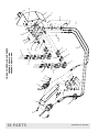
Loader Mount
(Left Side)
Optional Loader
Control Valve
10
8
MODELNO. SERIALNO. MASS (KG)
ID NO.
OREGON, IL U.S.A.
YR OF MFG.
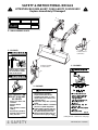
4 - SERIAL NUMBER PLATE
2 - PN 56053
WARNING
Read and understand Operator’s
Manual before operating.
(Replacement manuals are
available from dealer or, in the
United States and Canada, call
1-800-319-6637.)
Keep others away when operating
loader.
Do not allow children or untrained
persons to operate equipment.
Lower loader to ground, stop en-
gine, set park brake and remove
key before leaving tractor seat.
Failure to follow safety rules can
result in serious injury or death.
56051-A
(Safety Decals continued on next page)
56053-A
DANGER
ROLLOVERS CAN
RESULT IN INJURY
OR DEATH
Always use ROPS and
seat belt.
Add rear tractor
ballast.
Move wheels to widest
setting.
Avoid slope operation.
Operate at low speeds.
Carry load low.
Serious injury or death
can result from contact
with electrical lines.
DANGER
3 - PN 56051
1 - PN 56052
SAFETY & INSTRUCTIONAL DECALS
ATTENTION! BECOME ALERT! YOUR SAFETY IS INVOLVED!
Replace Immediately If Damaged!

SAFETY 5
PN-46018 (Rev. 11/10/00)
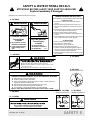
WARNING
56050-A
CRUSHING HAZARD
To avoid injury
or death:
Do not walk or work un-
derneath a raised loader.
Lower loader to ground
before leaving tractor
seat.
FALLING HAZARD
To avoid injury
or death:
Do not work from or
allow riders on loader or
its attachments.
WARNING
(Safety Decals continued from previous page)
56059-A
LOADER MOUNTING INSTRUCTIONS
Read Operator’s Manual instructions before proceding.
To Remove Loader
1. Park tractor on level surface with bucket flat on
ground.
2. Dump bucket to take weight off mount pins and
allow for stand installation. Set brake and shut off
tractor.
3. Remove standsfromcrosstube andpin intobrackets.
(Pin location noted in mounting manual.)
4. Remove mount pins from loader upright.
5. Roll back bucket completely to raise uprights from
mounts.
6. Shut off engine. Disconnect hydraulics. Back tractor
away. Store mount pins in loader uprights.
To Mount Loader
1. Remove mount pins from uprights.
2. Drive tractor into loader slowly.
3. Shut off tractor. Connect hydraulics.
4. Dump bucket to lower upright into mounts.
5. Continue dumping bucket until uprights settle into
mounts, pins can be installed and stands can be
removed. Set brake and shut off tractor.
6. Install mount pins and clips. Remove stands and pin
into crosstube.
LOADER ATTACHMENT CAN FALL OFF IF NOT PROPERLY ATTACHED.
Read operator’s manuals for instructions.
Position and align loader to attachment.
Rotate coupler handles to full locked position. Lockpins must fully extend and
engage into attachment retaining slots.
Attachment mechanism must be functional and in good repair.
Only use loader manufacturer approved attachments.
For information on approved attachments, call 1-800-319-6637.
Failure to follow these instructions can result in serious injury or death.
WARNING
56055-B
WARNING
Only use loader manufacturer approved attachments.
Failure to do so can cause serious injury or death.
45024-A
6 - PN 56050
5 - PN 19924
7 - PN 56055
11 - PN 45024
9 - PN 56059
Check for leaks with cardboard; never use hand.
Before loosening fittings: lower load, release pressure, and
be sure oil is cool.
Consult physician immediately if skin penetration occurs.
WARNING
19924-B
8 - PN 260274
(WHEN EQUIPPED)
260274-C
8 - PN 45002
(WHEN EQUIPPED)
56889
10 - PN 56889
(WHEN EQUIPPED)
SAFETY & INSTRUCTIONAL DECALS
ATTENTION! BECOME ALERT! YOUR SAFETY IS INVOLVED!
Replace Immediately If Damaged!

6 Mount Installation
PN-46018 (Rev. 3/15/02)
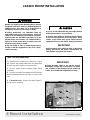
LOADER MOUNT INSTALLATION
■ Only use 111868 Loader Mounting Kit for mount-
ing Woods 1020/1027 loaders to Kubota M8200 and
M9000 tractors. Any other use or modification of
this kit may result in serious injury or death.
Safety instructions are important! Read all
attachment and power unit manuals; follow all
safety rules and safety decal information. (Replace-
ment manuals are available from dealer or, in the
United States and Canada, call 1-800-319-6637.)
Failure to follow instructions or safety rules can
result in serious injury or death.
Do not modify or alter or permit anyone else to
modify or alter the equipment or any of its compo-
nents in any way.
If you do not understand any part of this manual
and need assistance, see your dealer.
Always wear relatively tight and belted clothing
to avoid entanglement in moving parts. Wear
sturdy, rough-soled work shoes and protective
equipment for eyes, hair, hands, hearing, and head.
IMPORTANT
■ A front wheel track setting of 60.6” is the widest
setting allowed by the tractor manufacturer for
2WD models using front end loaders.
CAUTION
TRACTOR PREPARATION
For installing this mounting kit, references to right,
left, forward, and rearward directions are determined
from the operator’s position in the tractor seat.
1. Shut off engine and set parking brake during
installation.
2. Remove the tractor front weights and front weight
bracket if equipped. Remove tool box on tractors with
cab.
IMPORTANT
■ Clean threaded holes in the tractor chassis
thoroughly, using a tap of the proper size. Paint,
rust, or debris in the threads may not permit cap
screws to be installed and tightened correctly.
3. Cab tractors only – Remove four bolts (Figure 1)
for cab tractor mountings.
Figure 1 Remove 4 bolts on each side

Mount Installation 7
PN-46018 (3/15/02)
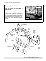
LOADER MOUNT INSTALLATION Cont’d
Figure 3
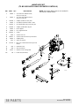
111868 Loader Mounting Kit
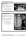
Remove Tractor Connector Tube or
Adapter Block
Follow this procedure only if using #40547 or
#46047 Hose Kits.
NOTE: It is easier to remove the connector tube or
adapter block before installing the right mount.
1. Remove tractor hydraulic line connector tube or
adapter block (if equipped) as shown in Figure 2.
2. To prevent the line from leaking during installation
of the loader mounts, be sure to plug the fitting. A 3/4”
plastic cap taken from an adapter in the hose kit may
be used.
Figure 2 Hydraulic connector Tube Removed
(Rear line capped with 3/4” plastic cap)
/,1(
&$33('
(1*,1( (1'
Grill Guard
1000545
RH Rear Mount
44490
LH Rear Mount
44491
Front Support
1002896
Crossmember
46000
RH Side Rail
59628
LH Side Rail
59631
Loader
Mounting
Instruction
Decal
56059
Spacer
Plate
46015
CD5612C-Var
Spacer
Plate
46015

8 Mount Installation
PN-46018 (Rev. 3/15/02)
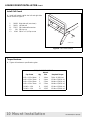
LOADER MOUNT INSTALLATION Cont’d
Install Crossmember
NOTE: Leave all cap screws loose until loader
mounts are completely installed.
1. Install #46000 crossmember to the underside of
the tractor clutch housing, using cap screws and
hardened flat washers as shown in Figure 4.
1. 307502 M18 x 1.5 x 85mm Cap screw
2. 57798 3/4 Hardened flat washer
3. 67376 M12 x 1.25 x 80mm Cap screw
4. 57816 1/2 Hardened flat washer
Figure 4 Crossmember Installed
&52660(0%(5
Install Rear Loader Mounts
1. Install #44490 right rear mount and #44491 left
rear mount to tractor chassis and crossmember.
NOTE: Non-cab tractors will need #46015 spacer
plate installed between the rear mounts and the trac-
tor.
2. Use cap screws (1) and hardened flat washers (2)
at tractor clutch housing as shown in Figure 5.
3. Use cap screws (3) and hardened flat washers (4)
to attach mount to crossmember.
1. 46019 M18 x 1.5 x 70mm Cap screw
2. 57798 3/4 Hardened flat washer
3. 12274 5/8 x 2-1/4 Cap screw
4. 57817 5/8 Hardened flat washer (hidden)
6. 230 5/8 Hex nut (hidden)
Figure 5 Left Rear Mount Installed
/2$'(5
02817
&52660(0%(5

Mount Installation 9
PN-46018 (3/15/02)
LOADER MOUNT INSTALLATION Cont’d
Install Front Mount Bracket
1. Install front mount bracket (3) to tractor steering
housing, using cap screws (17) and hardened flat
washers (11) as shown in Figure 6.
3. 1002896 Front mount bracket
11. 57817 5/8 Hardened flat washer
17. 307425 M16 x 1.5 x 35mm Cap screw
Figure 6 Front Mount Bracket
11
17
3
Install Side Rails
1. Install #59628 right side rail and #59631 left side
rail to outside of rear mounts as shown in Figure 7.
Secure with cap screws (13), hardened flat washers
(11), and hex nuts (12).
2. Secure at front support with cap screws (13), flat
washers (11), and hex nuts (12). Flat washers are
installed over the slot as shown below.
11. 57817 5/8 Hardened flat washer
12. 230 5/8 Hex nut
13. 4548 5/8 NC x 1-3/4 Cap screw
Figure 7 Side Rails Installed to Rear Mounts
& Front Support
/()7
/2$'(5
02817
13
11
12
13
11
12

10 Mount Installation
PN-46018 (Rev. 3/15/02)
LOADER MOUNT INSTALLATION Cont’d
Install Grill Guard
1. Install grill guard outside the left and right side
rails as shown in Figure 8.
5. 59628 Right side rail (not shown)
6. 59631 Left side rail
11. 57817 5/8 Hardened flat washer
12. 230 5/8 Hex nut
13. 4548 5/8 NC x 1-3/4 Cap screw
Figure 8 Grill Guard Installed
CD5612C-Var
13
11
12
6
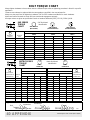
Torque Hardware
1. Tighten all hardware to specifications given.
TORQUE SPECIFICATIONS
Wrench
Cap Screw Qty Size Required Torque
M12 x 1.25 x 80mm 2 18mm 76 lbs.-ft.(103 N-m)
M16 x 1.50 x 35mm 6 24mm 133 lbs.-ft.(181 N-m)
M18 x 1.50 x 85mm 2 27mm 194 lbs.-ft.(263 N-m)
M18 x 1.50 x 70mm 12 27mm 194 lbs.-ft.(263 N-m)
5/8 NC x 1-3/4 8 15/16” 170 lbs.-ft.(230 N-m)
5/8 NC x 2-1/4 12 15/16” 170 lbs.-ft.(230 N-m)

Hydraulic Installation 11
PN-46018 (Rev. 3/15/02)
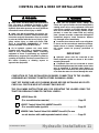
CONTROL VALVE & HOSE KIT INSTALLATION
■ Keep hands and body away from pressurized
lines. Use paper or cardboard, not hands or other
body parts to check for leaks. Wear safety goggles.
Hydraulic fluid under pressure can easily penetrate
skin and will cause serious injury or death.
■ Make sure that all operating and service per-
sonnel know that if hydraulic fluid penetrates skin,
it must be surgically removed as soon as possible
by a doctor familiar with this form of injury or gan-
grene, serious injury, or death will result. CON-
TACT A PHYSICIAN IMMEDIATELY IF FLUID
ENTERS SKIN OR EYES. DO NOT DELAY.
■ Air in hydraulic systems can cause erratic
operation and allow loads or equipment compo-
nents to drop unexpectedly. When connecting
equipment or hoses or performing any hydraulic
maintenance, purge any air in hydraulic system by
operating all hydraulic functions several times. Do
this before operating or allowing anyone to
approach the equipment.
■ Make sure all hydraulic hoses, fittings, and
valves are in good condition and not leaking before
starting power unit or using equipment. Check and
route hoses carefully to prevent damage. Hoses
must not be twisted, bent sharply, kinked, frayed,
pinched, or come into contact with any moving
parts. Operate moveable components through full
operational range to check clearances. Replace
any damaged hoses immediately.
■ Protective hose sleeves must cover all hydrau-
lic hoses and be secured onto metal hose fittings.
Replace hoses or sleeves if damaged or if protec-
tive sleeve cannot be properly positioned or
secured.
IMPORTANT
■ Hydraulic valves must be connected to the
tractor hydraulic system as shown in this loader
mounting kit manual.
■ If hydraulic lines are not connected as shown
in the mounting kit manual, the loader control valve
may be damaged. A blocked outlet (Return) or
improper hose connection will cause pressurized
oil to enter the return circuit and damage the valve.
COMPLETION OF THIS INSTALLATION REQUIRES CONNECTION TO THE LOADER,
ASSEMBLED ACCORDING TO INSTRUCTIONS IN MANUAL #56060.
SHUT OFF ENGINE AND LOCK PARKING BRAKE BEFORE INSTALLING HOSE KITS.
CHECK ALL PARTS IN HOSE KIT AGAINST PACKING LIST.
THE FOLLOWING INSTRUCTIONS ARE FOR OPERATING THE LOADER USING THE
TRACTOR HYDRAULIC REMOTE CONTROL LEVERS:
#40542 Hose Kit
(For use with tractor remotes). . . . . . . . . . . . . . . . . . . . . . . . . . . Page 12
#56037 Control Valve Kit & #40547 Hose Kit
(For use with loader joystick) . . . . . . . . . . . . . . . . . . . . . . . . . . .Page 15
#56038 Cable Control Valve Kit & #46047 Hose Kit (For use
on cab tractors with cable-operated control valve). . . . . . . . . .Page 21
1
2
3

12 Hydraulic Installation
PN-46018 (Rev. 3/15/02)
1
#40542 Hose Kit
(For use with tractor remotes)
NOTE: To use this hydraulic connection, the tractor
must be equipped with two hydraulic levers and four
tractor hydraulic couplers.
Install Hose Clamp Bracket & Channel
1. Install #40539 hose clamp bracket to right loader
mount, using carriage bolts (3), flat washers (4), lock
washers (5), and nuts as shown in Figure 9.
NOTE: Bracket must be installed before the loader is
mounted to the tractor.
2. With loader in mounting position, connect loader
supply hoses to the loader feedlines as shown in Fig-
ure 11.
3. Install #40548 hose clamp channel to hose clamp
bracket. Clamp hoses as shown in Figure 10.
5. 40539 Hose clamp bracket
6. 40548 Hose clamp channel
10. 35735 3/8 NC x 2-1/2 Carriage bolt
11. 66840 3/8 NC Knob
12. 3632 5/8 Flat washer
13. 1286 5/8 Lock washer
14. 230 5/8 NC Hex nut
15. 5607 5/8 NC x 1-1/2 Carriage bolt
Figure 9 Hose Clamp Assembly
Figure 10 Hose Clamp Bracket & Channel Installed
Figure 11 Loader Feedline Identifications
(viewed from rear)
+26( &/$03 &+$11(/
$
%
&
'
5+
/2$'(5
%220
$ %8&.(7 &</ %$6( (1'
'803
% %8&.(7 &</ 52' (1'
52//%$&.
& %220 &</ 52' (1'
'2:1
' %220 &</ %$6( (1'
83

Hydraulic Installation 13
PN-46018 (Rev. 3/15/02)
#40542 Hose Kit Cont’d
Route Hoses & Install Hose Support
1. Route hydraulic hoses along loader mount, under
right side of fuel tank, and over the rear axle. Be sure
to avoid contact with 3-point linkage, brake pedals,
and other moveable tractor components.
IMPORTANT
■ Hoses must be routed so that they are not
pinched bent sharply, or chafed during operation.
Hoses must not interfere with any tractor control
operation or contact any moving parts.
2. Attach #40543 hose support to tractor fuel tank
support channel, using existing tractor hardware from
the fuel tank support channel. Route hoses through
hose support.
Figure 12 Hose Support Installed
1
+26(
6833257
+26(
6833257
)8(/ 7$1.
6833257 &+$11(/
$
%RRP
/LIW +RVHV
%XFNHW
&\OLQGHU +RVHV
A. 66511 1/2 NPT Quick coupler
(not included)
1. 315058 1/2 NPT x 3/4 JICF Adapter
2. 313053 1/2 NPT x 3/4 JICF Elbow
3. 313032 3/4 JICM x 3/4 JICF Elbow
4. 53670 3/8 x 150” Hose
Figure 13 Hose Fitting Identifications
Install Fittings to Hoses
1. Attach two adapters (1), 90-degree elbows (2), and
quick couplers A (not included), to boom cylinder hoses.
2. Attach two 90-degree elbows (2) and quick couplers
(not included) to bucket cylinder supply hoses.

14 Hydraulic Installation
PN-46018 (Rev. 3/15/02)
#40542 Hose Kit Cont’d
Connect Hoses to Tractor
1. Connect hydraulic hoses to tractor hydraulic cou-
plers as shown in Figure 14.
2. Refer to tractor operator’s manual for operating
the tractor hydraulic levers.
Figure 14 Hose Connections to Tractor
Hydraulic Couplers
11
+26(
6833257
'
$
%
&
Verification of Control Movements
1. Comply with all Safety Rules and start the tractor.
2. Check that all hydraulic control lever posi-
tions operate the loader movements correctly as
shown in Figure 15.
3. If loader movements do not respond cor-
rectly, shut off tractor, relieve pressure, and
reconnect properly. Loader control movements
must be correct before proceeding.
4. Once all loader functions are correct, start
the tractor and operate the loader to check for
leaks. Purge any remaining air from the hydraulic
system.
5. When hose routings and correct loader oper-
ations are verified, identify each circuit by placing
a matching colored band around the male and
female quick-disconnect coupler set. The colored
bands will make re-installation easier when the
loader is removed from the tractor.
6. Be sure that adequate slack is left in the
hoses so they can move as the loader moves
through its full range of motion.
7.
Before operating the loader, make sure that the
Pre-Delivery, Delivery, and Pre-Operation Checklists
from the Operator section in the Loader Operator’s
Manual have been completed.
Figure 15 Tractor Hydraulic Control Levers
● Control #1, Handle forward - Boom down
● Control #1, Handle back - Boom up
● Control #2, Handle forward - Dump bucket or
attachment
● Control #2, Handle back - Rollback bucket or
attachment
&21752/
&21752/

Hydraulic Installation 15
PN-46018 (Rev. 3/15/02)
2
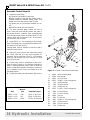
#56037 Control Valve & #40547 Hose Kit
(For use with loader joystick)
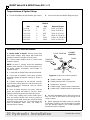
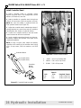
General Description
This hydraulic connection uses a single lever control
valve mounted on the right loader mount with a
bracket as shown in Figure 16.
Figure 16 #56037 Control Valve Installed
(Typical installation)

16 Hydraulic Installation
PN-46018 (Rev. 3/15/02)
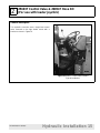
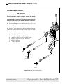
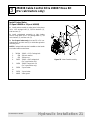
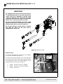
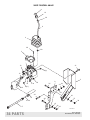
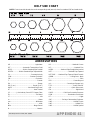
#56037 Valve Kit & #40547 Hose Kit Cont’d
Assemble Control Valve Kit
1. Install the control lever:
a) Thread end of handle (9) into valve.
b) Align handle so that end with longer bend is
pointing toward the adapter fittings. Make sure
bends are in line with front and rear of valve.
c) Tighten jam nut (38) already installed on han-
dle.
d) Slide boot down over boot bracket.
2. The valve mounting plate contains two sets of
holes. Select the holes that will position the valve in
the desired location. Install the valve mounting plate
(8) to the right loader mount, using two 5/8 NC x 1-1/2
carriage bolts (40), flat washers (41), lock washers
(42), and nuts (43) as shown.
3. Install 3/8 NC x 1-1/4 carriage bolt (30) through-
back of mounting shoe, securing with flat washer (32),
lock washer (33), and nut (34).
Carriage bolts must be installed so that the head is
inside the loader mount.
4. Attach the valve mount to the valve plate so that
the control valve will be in the correct position for
operation. Secure with three 1/2 NC x 1-1/2 carriage
bolts (35), flat washers (36), lock washers (37), and
nuts (39) as shown.
5. Control valve must be positioned so that move-
ment of tractor controls is not restricted. Maintain at
least 6” spacing between control valve kit and any
tractor control (brake pedals, accelerator, hand throt-
tle, or hydraulic levers.) Check for clearances in the
operating position.
6. Torque all hardware to specifications given below.
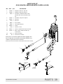
Figure 17 2-Spool Control Valve Kit Assembly
8. 46340 Valve mounting plate
9. 56254 Bent handle
17. 56095 3/8 x 54” Hose
30. 20973 3/8 NC x 1-1/4 Carriage bolt
32. 565 3/8 Flat washer
33. 838 3/8 Lock washer
34. 835 3/8 NC Hex nut
35. 12735 1/2 NC x 1-3/4 Carriage bolt
36. 3598 1/2 Flat washer
37. 855 1/2 Lock washer
38. 13859 Jam nut
39. 1093 1/2 Hex nut
40. 5607 5/8 NC x 1-1/2 Carriage bolt
41. 3632 5/8 Flat washer
42. 1286 5/8 Lock washer
43. 230 5/8 Hex nut
2
TORQUE SPECIFICATIONS
Wrench
Bolt Size Required Torque
3/8 NC x 1-1/4 9/16” 35 lbs.-ft. (47 N-m)
1/2 NC x 1-1/2 3/4” 85 lbs.-ft.(115 N-m)
5/8 NC x 1-1/2 15/16” 170 lbs.-ft.(230 N-m)
39
40
41
42
43
36
37
35
8
17
9
38
32
33
34
30
CD5733

Hydraulic Installation 17
PN-46018 (Rev. 3/15/02)
#56037 Valve Kit & #40547 Hose Kit Cont’d
2
4
15
2
2
3
4
4
7
7
IN
OUT
8
10
11
12
5
TRACTOR
PART
POWER
BEYOND
CD5558C
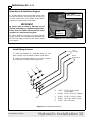
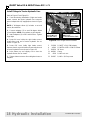
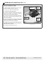
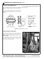
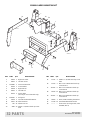
Assemble #40547 Hose Kit
IMPORTANT
■ If hydraulic lines are not connected as shown in the
mount installation manual or tractor manual, the loader
control valve may be damaged. A blocked outlet (return)
or improper hose connection will cause pressurized oil to
enter the return circuit and damage the valve or the trac-
tor hydraulic system.
1. Connect 90-degree end of 80” hose (8) to OUT port
adapter and tighten.
2. Connect two 54” hoses (7) to PBY and IN port adapaters.
3. Route 80” hose between tractor fuel tank and operator
platform to tractor Return port and connect, using 90° elbow
(5) and adapter (3).
2. 315038 1/2 NPTF x 3/4 JICM Adapter
3. 315058 1/2 NPTM x 3/4 JICF Adapter
4. 40549 1/2 NPTM x M26 x 1.5M 90° Elbow
5. 313032 3/4 JICM x 3/4 JICF 90° Elbow
7. 360130 54” Hose
8. 57911 80” Hose
Figure 17 #40547 Hose Kit Assembly

18 Hydraulic Installation
PN-46018 (Rev. 3/15/02)
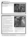
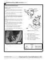
#56037 Valve Kit & #40547 Hose Kit Cont’d
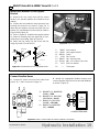
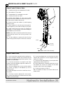
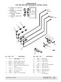
Install Fittings to Tractor Hydraulic Line
Refer to Figure 17 and Figure 18.
1. If not done during installation of right rear loader
mount, remove the tractor hydraulic line connector
tube or adapter block (if equipped) as shown in Figure
2.
NOTE: If 90-degree elbow (4) includes a nut and
sleeve, discard them.
2. Connect adapters (2) to each 90-degree elbow
(4) and tighten.
NOTE: Use sealant on pipe threads.
3. Attach adapters (2) to PBY and IN hoses. Tighten
finger tight.
4. Route IN hose inside the right loader mount.
Install elbow onto end of tractor hydraulic line as
shown in Figure 18.
5. Route PBY hose inside right loader mount.
Remove plastic cap and install onto transmission end
of tractor hydraulic line as shown in Figure 18.
6. Point elbows up and slightly out to clear the
hydraulic Return line as shown.
7. Tighten elbows to tractor line and tighten hoses to
adapters.
Figure 18 Hose Hanger Bracket Installed
2. 315038 1/2 NPTF x 3/4 JICM Adapter
4. 40549 1/2 NPTM x M26 x 1.5M 90° Elbow
7. 360130 54” Hose
11. 480261 Clamp
12. 6128 1/4 NC Lock nut
13. 300057 1/4 NC x 3/4 Cap screw
2
/,1(
6833257
%5$&.(7
)520 /2$'(5 9$/9(
3%< 3257
75$160,66,21 (1'
72 /2$'(5
9$/9( ,1 3257
(1*,1( (1'
Page is loading ...
Page is loading ...
Page is loading ...
Page is loading ...
Page is loading ...
Page is loading ...
Page is loading ...
Page is loading ...
Page is loading ...
Page is loading ...
Page is loading ...
Page is loading ...
Page is loading ...
Page is loading ...
Page is loading ...
Page is loading ...
Page is loading ...
Page is loading ...
Page is loading ...
Page is loading ...
Page is loading ...
Page is loading ...
Page is loading ...
Page is loading ...
Page is loading ...
Page is loading ...
-
 1
1
-
 2
2
-
 3
3
-
 4
4
-
 5
5
-
 6
6
-
 7
7
-
 8
8
-
 9
9
-
 10
10
-
 11
11
-
 12
12
-
 13
13
-
 14
14
-
 15
15
-
 16
16
-
 17
17
-
 18
18
-
 19
19
-
 20
20
-
 21
21
-
 22
22
-
 23
23
-
 24
24
-
 25
25
-
 26
26
-
 27
27
-
 28
28
-
 29
29
-
 30
30
-
 31
31
-
 32
32
-
 33
33
-
 34
34
-
 35
35
-
 36
36
-
 37
37
-
 38
38
-
 39
39
-
 40
40
-
 41
41
-
 42
42
-
 43
43
-
 44
44
-
 45
45
-
 46
46


Woods Equipment M8200 User manual
- Type
- User manual
Ask a question and I''ll find the answer in the document
Finding information in a document is now easier with AI
Related papers
-
Woods Equipment 211716 User manual
-
-
-
-
-
-
-
Woods Equipment 111877 User manual
-
-
Other documents
-
 MacDon MD #169589 A M205 Installation guide
-
Toro Bucket Mount Kit, Titan Riding Mower Installation guide
-
-
Woods LF138 User manual
-
-
-
-
Kubota LA302 Owner's manual
-
Toro Bucket Mount Kit, TimeCutter HD Riding Mower Installation guide
-
