INSTRUCTIONS FOR STORAGE
STEP 1. Disconnect 20’ coaxial cable from receiver.
STEP 2. Remove LNBF/feed tube assembly from dish
bracket assembly.
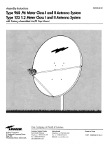
STEP 3. Store LNBF/feed tube assembly on top of dish
bracket assembly, with LNBF facing downward. Tighten
locking knob. See Figure 6.
FIGURE 6
STEP 4. Remove clevis pin and hair spring cotter from
legs and loosen elevation locking knob.
STEP 5. Swing legs underneath reflector and tip forward.
Insert clevis pin back into original hole and secure with
hair spring cotter. Tighten elevation locking knob.
If you require a replacement part, call Winegard Company
at 1-800-288-8094 between the hours of 8:00 a.m. and
4:00 p.m. central time, Monday through Friday. Credit card
holders only. If you need technical support, call 1-800-
788-4417.
INSTRUCTIONS FOR RECEIVING A SIGNAL
STEP 1. After assembling the antenna, make sure it is
resting on a flat level surface.
STEP 2. Determine the azimuth (direction) and elevation
angle (up/down) by entering your zip code into the appro-
priate set-up menu on your receiver.
STEP 3. To set the elevation angle (up/down), loosen the
knob on the “elevation bolt” and elevate the “dish bracket”
to the correct angle shown on the menu screen, by lining
up the colored edge on the clamp with the degree mark-
ing.
STEP 4. Using a compass, rotate the base slowly until
the center of the dish faces the desired azimuth angle
(direction) shown on the menu screen. The signal is digi-
tal; you must wait a few seconds after each move to
allow the receiver to process the signal.
STEP 5. Adjust azimuth (direction) and elevation (up/down)
for strongest signal.
HAIR SPRING COTTER
ELEVATION
KNOB
3-1/2” x 1/4”
CLEVIS PIN
LOCKING KNOB
LNBF FEED
TUBE ASSEMBLY
WINEGARD MOBILE PRODUCTS LIMITED WARRANTY
(2 YEARS PARTS; 1 YEAR LABOR)
Winegard Company warrants this product against defects in
materials or workmanship for a period of two (2) years from the date
of original purchase. During year one (1) of such warranty, Winegard
Company will also pay authorized labor costs to an authorized Winegard
dealer to repair or replace defective products. No warranty claim will
be honored unless at the time the claim is made, Customer presents
proof of purchase to an authorized Winegard dealer (to locate the
nearest authorized Winegard dealer, contact Winegard Company, 3000
Kirkwood Street, Burlington, Iowa 52601, Telephone 800-288-8094 or
visit www.winegard.com). Customer must provide proof of purchase
with a dated sales receipt for the Winegard product to verify the
product is under warranty. If the date of purchase cannot be verified,
the warranty period shall be considered to begin thirty (30) days after
the date of manufacture.
If a defect in material or workmanship is discovered, Customer may
take the product to an authorized Winegard dealer for service. Customer
must provide proof of purchase to verify the product is under warranty.
If the product is brought to an authorized Winegard dealer for service
prior to expiration of year one (1) of the warranty period and a defect
in material or workmanship is verified by Winegard Technical Services,
Winegard Company will cover the Winegard dealer’s labor charges for
warranty service. The Winegard dealer must contact Winegard Technical
Services in advance for pre-approval of the service. Approval of the
service is at the sole discretion of Winegard Company.
Alternatively, Customer may ship the product prepaid to Winegard
Technical Services (located at 3111 Kirkwood Street, Burlington, Iowa
52601, Telephone 800-788-4417). Customer must return the product
along with a brief description of the problem and provide Winegard
Technical Services with Customer’s name, address, and phone
number. Customer must also provide proof of purchase to verify
the product is under warranty. If the product is returned before the
expiration of the warranty period, Winegard Company will (at its
option) either repair or replace the product.
This Limited Warranty does not apply if the product has been
damaged, deteriorates, malfunctions or fails from: improper
installation, misuse, abuse, neglect, accident, tampering, modifica-
tion of the product as originally manufactured by Winegard in any
manner whatsoever, removing or defacing any serial number, usage
not in accordance with product instructions or acts of nature such
as damage caused by wind, lightning, ice or corrosive environments
such as salt spray and acid rain. This Limited Warranty also does
not apply if the product becomes unable to perform its’ intended
function in any way as a result of the television signal provider
making any changes in technology or service.
RETURN AUTHORIZATION POLICY
A Return Material Authorization (RMA) is required prior to returning
any product to Winegard Company or Winegard Warranty Services
under this warranty policy. Please call our Technical Services
Department at 800-788-4417 or send an e-mail to
the date of purchase when requesting an RMA number. Enclose the
product in a prepaid package and write the RMA number in large,
clear letters on the outside of the package. To avoid confusion or
misunderstanding, a shipment(s) without an RMA number(s) or an
unauthorized return(s) will be refused and returned to Customer
freight collect.
WINEGARD COMPANY DOES NOT ASSUME ANY LIABILITIES
FOR ANY OTHER WARRANTIES, EXPRESS OR IMPLIED, MADE
BY ANY OTHER PERSON.
ALL OTHER WARRANTIES WHETHER EXPRESS, IMPLIED OR
STATUTORY INCLUDING WARRANTIES OF FITNESS FOR A
PARTICULAR PURPOSE AND MERCHANTABILITY ARE LIMITED
TO THE TWO YEAR PERIOD OF THIS WARRANTY.
In states that do not allow limitations on implied warranties, or the
exclusion of limitation of incidental or consequential damages, the
above limitations or exclusions do not apply.
Some states do not allow limitations on how long an implied
warranty lasts, or the exclusion of limitation of incidental or
consequential damages, so the above limitations or exclusions may
not apply to you.
This warranty gives Customer specific legal rights. Customer may
also have other rights that may vary from state to state.
SATELLITE RECEIVER WARRANTY
See manufacturer’s limited warranty policy.
WS-MOBWARREV2
Rev. 1/10