La Crosse Technology WS-7213U User manual

Category
Weather stations
Type
User manual

La Crosse Technology WS-7213U is an advanced weather station with wireless sensor capabilities, allowing you to monitor indoor and outdoor temperature, as well as humidity levels. Its weather forecast feature provides a 75% accurate prediction based on air pressure changes, displayed with intuitive weather icons and tendency arrows. With the option to connect up to 3 remote sensors, you can monitor conditions in different areas simultaneously, making it perfect for homes, offices, or even greenhouses.

La Crosse Technology WS-7213U is an advanced weather station with wireless sensor capabilities, allowing you to monitor indoor and outdoor temperature, as well as humidity levels. Its weather forecast feature provides a 75% accurate prediction based on air pressure changes, displayed with intuitive weather icons and tendency arrows. With the option to connect up to 3 remote sensors, you can monitor conditions in different areas simultaneously, making it perfect for homes, offices, or even greenhouses.

WS-7213U
Wireless 433 MHz
Weather Station
Instruction Manual
2
TABLE OF CONTENTS
Topic Page
Inventory of Contents 3
Additional Equipment 4
Quick Setup 5-8
Detailed Setup Guide
Battery Installation 9-11
Setting the Time 11
Features
Minimum and Maximum
Temperatures
12-13
Resetting Minimum and
Maximum Temperatures
13
Weather Forecast and Weather
Tendency Arrows
14-17
Adding additional remote
temp/humidity sensors
(optional)
17-19
Viewing and operating multiple
remote temp/humidity sensors
19-20
Mounting 21-22
Troubleshooting 23-26
Maintenance and Care 26
Specifications 27-28
Warranty Information 29-31
3
INVENTORY OF CONTENTS
1. The indoor weather
station (Figure 1)
2. The remote
temperature/humidity
sensor (TX4U) and
mounting bracket.
(Figure 2)
3. Mounting hardware.
4. Instruction Manual
and Warranty Card.
Figure 2
Figure 1
4
ADDITIONAL EQUIPMENT
(not included)
1. 1 Philips screwdriver.
2. 2 Fresh AA 1.5V batteries.
(for the indoor weather station)
3. 2 Fresh AA 1.5V batteries.
(for the temp/humidity sensor)
5
QUICK SETUP
Hint: Use good quality Alkaline Batteries
and avoid rechargeable batteries.
1. Have the indoor weather station and
remote temp/humidity sensor 3 to 5 feet
apart.
2. Batteries should be out of all units for
10 minutes.
3. Place the batteries into the remote
temp/humidity sensor first, then into
the indoor weather station.
(All remote temp/humidity sensors
must be started before the indoor
weather station)
4. DO NOT PRESS ANY BUTTONS
FOR 15 MINUTES.
6
In this time the indoor weather station and
remote temp/humidity sensor will start to
talk to each other and the displays will show
both the indoor temperature and an outdoor
temperature and humidity. If the indoor
weather station do not display both the
indoor temperature and the outdoor
temperature and humidity after the 15
minutes please retry the set up as shown on
page five.
After both indoor temperature and outdoor
temperature and humidity are displayed for
10 minutes you can place your remote
temp/humidity sensor outdoors and set your
time.
7
Notes on Outdoor Sensor Placement
The remote temp/humidity sensor should be
placed in a dry, shaded area. Fog and mist
will not harm your remote temp/humidity
sensor but direct rain must be avoided.
The remote temp/humidity sensor has a
range of 80 feet. Any walls that the signal
will have to pass through will reduce
distance. An outdoor wall or window can
have up to 30 feet of resistance and an
interior wall can have up to 20 feet of
resistance. Your distance plus resistance
should not exceed 80 ft. in a straight line.
Notes on Weather Station Placement
The 80 ft distance is between each indoor
weather station and the temp/humidity
sensor independently. The placement of one
indoor weather station does not affect the
placement of a second indoor weather
station.
8
To complete the set up of your indoor
weather station after the 10 minutes have
passed, please follow the steps below.
1. Press and hold the “SET” button for
five seconds.
2. The hour will now be flashing.
a. Press and release the “+”
button until the correct hour
is shown.
Note: There is “PM” displayed to
the left of the hour when between
noon and midnight. During the
AM hours this area will be blank.
b. When the correct hour is
shown, press and release the
“SET” button once.
3. The minutes will now be flashing.
a. Press and release the “+”
button until the correct
minutes are displayed.
Press and release the SET button once
more and you are done.
9
Battery
compartment
DETAILED SETUP GUIDE
I. BATTERY INSTALLATION
A. REMOTE TEMP/HUMIDITY
SENSOR
1. Remove the mounting bracket.
2. Remove battery cover
3. Observing the correct polarity, install
2 AA batteries—make sure they do not
spring free, or start-up problems may
occur.
4. Replace cover.
Battery cover
10
B.
INDOOR WEATHER STATION
Note:
After the batteries are installed, DO
NOT press any buttons for 15 minutes. This
may interfere with the signals, causing
temperatures to register incorrectly.
1. Remove the
battery cover
on the
backside. To
do this, push
up and pull
out.
2. Observing
the correct
polarity,
install 2 AA
batteries.
3. Replace battery cover.
4. Wait 15 minutes or until both the
indoor and outdoor temperatures are
shown on the indoor weather station.
Battery cover
Battery
Compartment
11
5.
The indoor weather station should
now show: “-:- -” in the TIME LCD,
indoor temperature in the INDOOR
LCD and outdoor temperature and
humidity in the OUTDOOR LCD.
II. SETTING THE TIME
1. Press and hold the “SET” button for 5
seconds.
2. The hour will begin to flash.
3. Press and release the “+” button to
advance the hour to your desired hour.
4. Press and release the “SET” button to
move to the minute setting.
5. The minutes will begin to flash.
6. Press and release the “+button to set
the minutes.
7. Press and release the “SET” button to
activate the clock.
Note: There is “PM” displayed to the left of
the hour when between noon and midnight.
During the AM hours this area will be blank.
12
FEATURES
A. MINIMUM AND MAXIMUM
TEMPERATURES
1. Press and release
the “MIN/MAX”
button, “MAX”
appears at the bottom
of the display and
the recorded
maximum
temperatures are
displayed.
2. Press and release the
MIN/MAX” button
to toggle to the
minimum
temperatures, “MIN”
appears at the bottom
of the display and the
recorded minimum
temperatures are
13
displayed.
B. RESETTING THE MINIMUM AND
MAXIMUM TEMPERATURES
To reset both the minimum and
maximum temperatures—press and hold
the “MIN/MAX” button for 5 seconds.
14
C. WEATHER FORECAST
The weather forecasting feature is
estimated to be 75% accurate. The
weather forecast is based solely upon the
change of air pressure over time. The
WS-7213U averages past air-pressure
readings to provide an accurate
forecast—creating a necessity to
disregard all weather forecasting for 12-
24 hours after the unit has been set-up,
reset, or moved from one altitude to
another (i.e. from one floor of a building
to another floor). In areas where the
weather is not affected by the change of
air pressure, this feature will be less
accurate.
15
1. Weather Icons
There are 3 possible weather icons that
will be displayed in the FORECAST
LCD:
Sunny—indicates
that the weather is
expected to improve
(not that the weather
will be sunny).
Sun with Clouds
indicates that the
weather is expected
to be fair (not that
the weather will be
sunny with clouds).
Clouds with Rain
indicates that the
weather is expected
to get worse (not that
the weather will be
rainy).
16
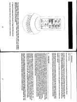
The weather icons change when the unit
detects a change in air pressure. The
icons change in order, from “sunny” to
“partly sunny” to “cloudy” or the
reverse. It will not change from “sunny”
directly to “rainy”, although it is possible
for the change to occur quickly. If the
symbols do not change then the weather
has not changed, or the change has been
slow and gradual.
2. Weather Tendency Arrows
Other possible displays in the
FORECAST LCD are 2 weather
tendency arrows, one that points up (on
the left side of the LCD) and one that
points down (on the right side of the
LCD). These arrows reflect current
changes in the air pressure. An arrow
pointing up indicates that the air pressure
is increasing and the weather is expected
to improve or remain good. An arrow
17
pointing down indicates that the air
pressure is decreasing and the weather is
expected to become worse or remain
poor. No arrow means the pressure is
stable and the weather should remain
relatively the same
D. ADDING ADDITIONAL
REMOTE TEMP/HUMIDITY
SENSORS (OPTIONAL)
The WS-7213U is able to receive signals
from 3 different remote temperature,
temperature/humidity sensors. Following
are some brief instructions for the basic
set-up of remote sensor units with the
WS-7213U. These extra sensors can be
purchased through the same dealer as
this unit, or by contacting La Crosse
Technology directly. A TX6 will
monitor temperature only, a TX3U will
monitor temperature and display the
temperature on its LCD, the TX3UP will
18
monitor the temperature via a probe for
use in pools, spas, etc and the TX4U will
monitor temperature and humidity.
Note: When setting up multiple units it
is important to remove the batteries from
all existing units in operation, then to
insert batteries first into all the remote
sensor units, and in numeric sequence.
Second, install batteries into the indoor
weather station. Transmission problems
will arise if this is not done correctly and
if the total time for set-up exceeds 6
minutes.
1. It is necessary to remove the batteries
from all units currently in operation.
2. Remove the battery covers to all
remote sensor units.
3. Place all remote sensor units in a
numeric sequential order.
4. In sequential order, install batteries
(follow the same battery installation
19
procedures seen in section “I” of the
Detailed Set-Up Guide) into the
remote sensors.
5. Install batteries into the indoor
weather station.
Follow the Detailed Set-Up Guide for
programming and operating instructions.
E. VIEWING AND OPERATING
WITH MULTIPLE REMOTE
SENSOR UNITS
1. To view the temperature of a different
remote sensor unit, press and release
the “CH” button. A shift from one
“boxed” number to the next should be
observed in the OUTDOOR LCD.
20
2.
To view the Minimum/Maximum
temperature: first select from which
remote temp/humidity sensor to read
data from (indicated by the “boxed”
number). Pressing and releasing the
“MIN/MAX” button will toggle
through the minimum and maximum
indoor temperature, and the minimum
and maximum outdoor temperature.
3. To reset the Minimum/Maximum
readings, press and hold the
“MIN/MAX” button for five seconds.
  • Page 1 1
  • Page 2 2
  • Page 3 3
  • Page 4 4
  • Page 5 5
  • Page 6 6
  • Page 7 7
  • Page 8 8
  • Page 9 9
  • Page 10 10
  • Page 11 11
  • Page 12 12
  • Page 13 13
  • Page 14 14
  • Page 15 15
  • Page 16 16
  • Page 17 17
  • Page 18 18
  • Page 19 19
  • Page 20 20
  • Page 21 21
  • Page 22 22
  • Page 23 23
  • Page 24 24
  • Page 25 25
  • Page 26 26
  • Page 27 27
  • Page 28 28
  • Page 29 29
  • Page 30 30
  • Page 31 31
  • Page 32 32
  • Page 33 33
  • Page 34 34
  • Page 35 35
  • Page 36 36
  • Page 37 37
  • Page 38 38
  • Page 39 39
  • Page 40 40
  • Page 41 41
  • Page 42 42
  • Page 43 43
  • Page 44 44
  • Page 45 45
  • Page 46 46
  • Page 47 47
  • Page 48 48
  • Page 49 49
  • Page 50 50
  • Page 51 51
  • Page 52 52
  • Page 53 53

La Crosse Technology WS-7213U User manual

Category
Weather stations
Type
User manual

La Crosse Technology WS-7213U is an advanced weather station with wireless sensor capabilities, allowing you to monitor indoor and outdoor temperature, as well as humidity levels. Its weather forecast feature provides a 75% accurate prediction based on air pressure changes, displayed with intuitive weather icons and tendency arrows. With the option to connect up to 3 remote sensors, you can monitor conditions in different areas simultaneously, making it perfect for homes, offices, or even greenhouses.

Ask a question and I''ll find the answer in the document

Finding information in a document is now easier with AI