Kenmore POWER MISER 153.33616 User manual
- Category
- Water heaters & boilers
- Type
- User manual

Owner's Manual
POWER MISER TM6
GAS WATER HEATER
FOR POTABLE WATER HEATING ONLY,
NOT SUITABLE FOR SPACE HEATING
NOT FOR USE IN MOBILE HOMES.
MODEL NO.
153.336160
153.336260
153.336300 HA
153.336360
153.336400 HA
153.336464
153.336500 HA
153.336560
153.336760
153.336800 HA
153.336860
153.336900 HA
153.336960
30 Gallon Short
40 Gallon Short
30 Gallon High Altitude
30 Gallon
40 Gallon High Altitude
40 Gallon
50 Gallon High Altitude
50 Gallon
30 Gallon Propane (LP.)
40 Gallon Propane (L.P.) High Altitude
40 Gallon Propane (LP.)
50 Gallon Propane (L.P.) High Altitude
50 Gallon Propane (LP.)
i
• Safety Instruction
• Installation
• Operation
• Care and Maintenance
• Troubleshooting
• Parts List
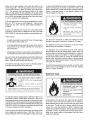
For Your Safety
AN ODORANT ISADDEDTOTHE GASUSED BYTHIS WATER HEATER.
C3 Technology TM Gas Water Heaters meet
the new ANSI Z21,10,1 standard that deals
with the accidental or unintended ignition
of flammable vapors, such as those
emitted by gasoline.
Read and understand instruction
manuai and safety messages
before installing, operating or
servicing this water heater
Failure to fallow instructionsand
safety messages could result in
death or serious injury
Instruction manua! must remain
with water heater
Sino puedeleer oentender elingles y necesita el manual instructivo
y/o etiquetas en esparlol puede obtenerlos Ilamando al
1-800-821-2017. NO TRATE DE ]NSTALAR O OPERAR ESTE
CALENTADORDEAGUAsi noenflendelainformaciOnen lasetiquetas
oen el manualinstructivo. No hacer casode esta advertencia podrla
resultaren laMUERTEO GRAVESLESIONESCORPORALES.
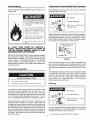
WARNING: If the information in these
instructions is not followed exactly, a fire
or explosion may result causing property
damage, personal injury or death.
--Do not store or use gasoJine or other
flammable vapors and liquids in the
vicinity of this orany other appliance.
-- WHAT TO DO IF YOU SMELL GAS:
= Do not try to light any appliance
• Do not touch any electrical switch; do
not use any phone in your building.
,, immediately call your gas supplier
from a neighbor's phone. Follow the
gas supplier's instructions.
• if you cannot reach your gas supplier,
call the fire department.
--installation and service must be
performed by a qualified installer,
service agency or the gas supplier.
Sears, Roebuck and Co., Hoffman Estates, IL 60179 U.S.A
PART NO 184482-000
PRINTED IN THE US.A 0703 www.sears.com SUPERSEDES PART NO. 184437-000 & 184255-000

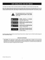
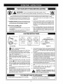
Your safety and the safety of others is extremely important in the installation, use and servicing of this water heater.
Many safety-related messages and instructions have been provided in this manual and on your own water heater to warn you and
others of a potential injury hazard. Read and obey all safety messages and instructions throughout this manual. It is very
important that the meaning of each safety message is understood by you and others who install, use or service this water heater.
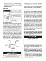
This is the safety alert symbol. It is used to alert you
to potential personal injury hazards. Obey all safety
messages that follow this symbol to avoid possible
injury or death.
DANGER indicates an imminently
hazardous situation which, if not avoided,
could result in death or injury.
WARNING indicates a potentially hazardous
situation which, if notavoided, could result
in death or injury.
CAUTION indicates apotentially hazardous
situation which, if not avoided, may result
in minor or moderate injury.
CAUTION used without the safety alert
symbol indicates a potentially hazardous
situation which, if notavoided, could result
-- in property damage.
All safety messages will generally tell you about the type of hazard, what can happen if you do not follow the safety message and
how to avoid the risk of injury.
IMPORTANT DEFINITIONS
Gas Supplier: The natural gas or propane utility or service who supplies gas for utilization by the gas burning
appliances within this application. The gas supplier typically has responsibility for the inspection and code approval of
gas piping up to and including the natural gas meter or propane storage tank of a building. Many gas suppliers also
offer service and inspection of appliances within the building.
© Sears, Roebuck and Co.
2

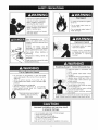
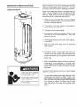
Read and understand instruction
manual and safety messages
before installing, operating or
servicing this water heater
Failure to follow instructions and
safety messages could result in
death or serious Injury
blstruction manual must [emain
with water heater
_LJ_ Fire Hazard
_,_, For continued protection against
risk of fire;
_., ,Do not install water heater on
W _v I carpeted floor.
_ ,Do not operate water heater if
, _ j flood damaged
Water temperature over 125°F
(52°C) can cause severe burns
instantly result ng in severe injury
or death.
Children, the elderly, and the
physically or mentalJy dJsabted
are at highest riskfor scald injury.
Feel water before bathing or
showering.
Temperature limiting valves are
available
Read instruction manual for safe
temperature setting
Fire or Explosion Hazard
- Do not store or use gasoline or other flammable
vapors and liquids n the vicinity of this or any other
appliance
• Avoid all ignition sources if you smell LP gas.
• Do not expose water heater control to excessive gas
pressure
• Use only gas shown on rating plate.
• Maintain required clearances to combustibles
• Keep ignition sources away from faucets after
,- extended period of non-use.
Read instruction manual before
installing, using or servicing
water heater
Explosion Hazard
• Overheated water can cause
water tank explosion
• Properly sized tempeature
end pressure relief valve must
be installed in opening
provided
Breathing Hazard - Carbon Monoxide Gas
O
• install vent system in accordance with
codes
• Do not operate water heater if flood
damaged
• High altitude orifice mustbe installed for
operation above 3,300 feet (1,006 m)
(or above 5500 (I ,676 m) feet for high
altitude models)
, ; ° Do not operateifsoot buildup.
• Do not obstruct water heater air intake
with insulating jacket.
° Do not place chemical vapor emitting
products near water heater
° Gas and carbon monoxide detectors
are availa b/e
Breathing carbon monoxide can cause brain damage or
death. Always read and understand instruction manual
Improper installation and use may result
in property damage.
• Do not operate water heater if flood damaged.
• Inspect and replace anode
• Install in location with drainage.
• Fill tank with water before operat on
• Be alert for thermal expansion
Refer to instruction manual for installation and service.
3


ThankYou for purchasing a Kenmore water heater. Propedy
installed and maintained, it should give you years of trouble
free service. If you should decide that you want the new water
heater professionally installed by Sears call 1-800-4-MY-HOME ®.
They will arrange for prompt, quality installation by Sears
authorized contractors.
Abbreviations Found In This Instruction Manual:
CSA - Canadian Standards Association
ANSI - American National Standards Institute
NFPA- National Fire Protection Association
ASME - American Society of Mechanical Engineers
GAMA - Gas Appliance Manufacturers Association
This gas-fired water heater is design certified by CSA
INTERNATIONAL under American National Standard/CSA
Standard for Gas Water Heaters ANSI Z21.10.1 • CSA 4.1
(current edition).
Read the "Safety Precautions" section, page 3 of this manual
first and then the entire manual carefully. If you don't follow
the safety rules, the water heater will not operate properly. It
could cause DEATH, SERIOUS BODILY INJURY AND/OR
PROPERTY DAMAGE.
This manual contains instructions for the installation,
operation, and maintenance of the gas-fired water heater. It
also contains warnings through out the manual that you must
read and be aware of. All warnings and all instructions are
essential to the proper operation of the water heater and
your safety. Since we cannot put everything on the first few
pages, READ THE ENTIRE MANUAL BEFORE ATTEMPTING
TO INSTALL OR OPERATE THE WATER HEATER.
• The installation must conform with these instructions and
the local code authority having jurisdiction. In the absence of
local codes, installations shall comply with the following:
In the United States: The National Fuel Gas Code ANSI
Z223.1/NFPA 54. This publication is available from the
Canadian Standards Association, 8501 East Pleasant Valley
Rd, Cleveland Ohio 44131, or The National Fire Protection
Association, 1 Batterymarch Park, Quincy, MA 02269.
• If after reading this manual you have any questions or do not
understand any portion of the instructions, call the Sears
Service Center.
• Carefully plan the place where you are going to put the water
heater. Correct combustion, vent action, and vent pipe
installation are very important in preventing death from
possible carbon monoxide poisoning and fires. See
figure 1.
Examine the location to ensure the water heater complies
with the Facts to Consider About the Location section in this
manual.
• For California installation this water heater must be braced,
anchored, or strapped to avoid falling or moving during an
earthquake. See instructions for correct installation
procedures. Instructions may be obtained from your local
dealer, wholesaler, public utilities or California Office of the
State Architect, 400 P Street, Sacramento, CA 95814.
• Massachusetts Code requires this water heater to be
installed in accordance with Massachusetts 248-CMR 2.00:
State Plumbing Code and 248-CMR 5.00.
• Complies with SCAQMD rule #1121 and districts having
equivalent NOx requirements.
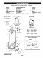
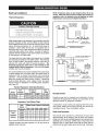
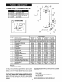
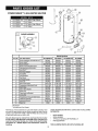
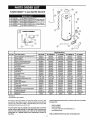
RECOVERY MINIMUM DIMENSIONS
TANK TYPE RATE GAL8. VENTPIPE DIAMETER IN INCHES (mm)
MODEL CAPACITY OF B'ru PERHOUR INCHES INCHES HEIGHTTO
NUMBER IN GALS (LTRS) GAS RATE @ 90=F RISE (mm) (mm) JACKETTOP
153336160 30(114) NATURAL 32,000 32.8 3"(76)or 4"(102) 181/4"(464) 433/4"(1,111)
153.336260 40 (151) NATURAL 35,500 36.3 3" (76) or 4" (102) 20 1/4" (514) 47 1/4" (1,200)
153.336300 HA 30(114) NATURAL 35,500 36.3 3"(76) 153/4" (400) 571/2"(1,461)
153.336360 30(114) NATURAL 35,500 36.3 3"(76) 153/4"(400) 571/2"(1,461)
153.336400 HA 40 (151) NATURAL 35,500 36.3 3" (76) 18 1/4" (464) 55 1/2" (1,410)
153.336464 40 (151) NATURAL 35,500 36.3 3" (76) 18 1/4" (464) 55 1/2" (1,410)
153.336500 HA 50 (189) NATURAL 35,500 36.3 3" (76) 20 1/4" (514) 56 1/2" (1,435)
153.336560 50 (189) NATURAL 35,500 36.3 3" (76) 20 1/4" (514) 56 1/2" (1,435)
153.336760 30(114) PROPANE 35,500 36.3 3"(76) 153/4"(400) 571/2"(1,461)
153.336800 HA 40 (151) PROPANE 35,500 36.3 3" (76) 18 1/4" (464) 55 1/2" (1,410)
153.336860 40 (151) PROPANE 35,500 36.3 3" (76) 18 1/4" (464) 55 1/2" (1,410)
153.336900 HA 50 (189) PROPANE 35,500 36.3 3" (76) 20 1/4" (514) 56 1/2" (1,435)
153.336960 50 (189) PROPANE 35,500 36.3 3" (76) 20 1/4" (514) 56 1/2" (1,435)

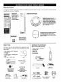
Materials Needed
To simplify the installation Sears has available the installation parts shown below. You may or may not need all of these materials,
depending on your type of installation.
WATER HEATER tl__.l_<_ ,,,,_
IBSTA T,O. .......
KIT WITH FLEXIBLE _,;_, I
CONNECTORS i!¸_ _!: !
FOR 3/4" (10.05 ram)
OR 112" (12.7 ram)
THREADEDOR
COPPER PLUMBING
FLEXIBLE WATER HEATER GAS
CONNECTOR WITH FITTINGS
DRAIN PANS AVAILABLE IN 20" (508 mm)
DIAMETER FOR WATER HEATERS
HAVING A DIAMETER t8" (457 ram) OR
LESS, 24" (6t6mm) DIAMETER FOR
WATER HEATERS HAVING A DIAMETER
22" (559 mm) OR LESSAND AVAILABLE
IN 28" (7tl ram) DIAMETER FOR WATER
HEATERS HAVING A DIAMETER 26"
(660 mm) OR LESS
i_ J,_N_ _T_ _r_ WATER HEATER HEAT
TRAPS HELP REDUCE
I I HEAT LOSS DUE TO
EXPANSION TANKS FOR THERMAL EXPANSION
CONDITIONS AVAILABLE IN 2 GALLONS
(7.6 LITERS) AND 6 GALLONS (t8.9 LITERS)
CAPACITY THROUGH LOCAL SEARS STORE OR
SERVICE CENTER
Basic Tools
You may or may not need all these tools, depending on your
type of installation. These tools can be purchased at your local
Sears Store.
Pipe Wrenches (2) 14" (356 mm) ;_
Screwdriver
Tin Snips
6' (1.82 m) Tape or Folding Ruler
Garden Hose
Drill
Pipe Dope or Teflon Tape DRILL
SLOT-HEAD SCREWDRIVER
PHILLIPS SCREWDRIVER
ROLL OF TEFLON
TAPE (USE ONLY OH
WATER HEATER
CONNECTIONS)
TIN SNIPS
PIPE DOPE
(SQUEEZE TUBE)
USE FOR WATER AND GAS
CONNECTIONS
GARDEN HOSE 6 FOOT TAPE PIPE WRENCH
Additional Tools Needed
When Sweat Soldering
Tubing Cutters or Hacksaw
Propane Tank
Soft Solder
Solder Flux
Emery Cloth
Wire Brushes
TUBING CUTTER
PROPANE
TORCH
HACKSAW
ROLL OF
EMERY CLOTH
3/4" (19 mm) WIRE BRUSH
t/2" (t3 mm) WINE BRUSH
ROLL OF LEAD-FREE
SOFT SOLDER
SOLDER
FLUX

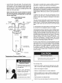
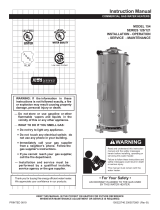
GET TO KNOW YOUR WATER HEATER - GAS MODELS
A Vent Pipe
B Draft Hood
C Anode
D Hot Water Outlet
E Outlet
F Flexible Water Connections
G Gas Supply
H ManuaIGas Shut-offValve
I Ground Joint Union
J Drip Leg (Sediment Trap) S Flue Baffle
K Inner Door T Thermostat
L Outer door U Drain Valve
M Union V Pilotand Main Burner
N Inlet Water Shut-off Valve W Flue
O Cold Water Inlet X Drain Pan
P Inlet DipTube Y Thermostat Shield (optional)
Q Temperature-Pressure Relief Valve Z Piezolgnitor
R Rating Plate AA Air Intake Screen
* INSTALL INACCORDANCE
WITH LOCAL CODES.
* DRIP LEG AS REQUIRED
BY LOCAL CODES.
TOVENTTERMINATION
ON ROOF
A
INSTALL THERMAL EXPANSION
TANK IF WATER HEATER
IS INSIALLED IN A CLOSED
WATER SYSTEM
B
W
Q
AA
K
*ALL PIPINGMATERIALSTO BE L_
SUPPLIEDBY CUSTOMERS.
FIGURE1.
7
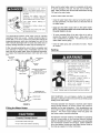
(T) THERMOSTAT
GAS CONTROL KNOB
WATER TEMPERATURE
(ADJUSTING DIAL)
"OFF .... PILOT .... ON" i
POSITION POSITION POSITION i
TOPVIEW
(V) PILOT & MAIN BURNER
BURNER TUBE
k/ NAIN BURNER
TH ER_:)COU PLE f_
PILOT TUBING / • PILOT BURNER
THERMOCOUPLE
TGO

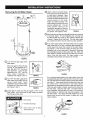
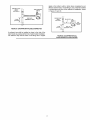
Removing the Old Water Heater
q
FIGURE2.
Q Turn "OFF" the gas supply to the
water heater.
If the main gas line Shut-off valve
serving all gas appliances is
used, also shut "OFF" the gas at
each appliance. Leave all gas
appliances shut "OFF" until the
water heater installation is
completed, see Figures 2 and 3.
FIGURE&
(_) Turn the water supply to the
"OFF"
water heater at the water shut off
valve or water meter. Some
installations require that the water
be turned off to the entire house,
see Figures 2 and 4.
FIGURE&
(_) Check again to make sure the supply is "OFF" to the
gas
water heater. Then disconnect the gas supply connection
from the gas control valve.
• Burn hazard
- Hot water discharge.
, Keep hands clear of drain
valve discharge.
(_ Attach hose to the water heater
a
drain valve and put the other end
in a floor drain or outdoors. Open
the water heater drain valve. Open
a nearby hot water faucet which will
relieve pressure in the water
heater and speed draining. The
water passing out of the drain valve
may be extremely hot. To avoid
being scalded, make sure all
connections are tight and that the
water flow is directed away from
any person, see Figures 2 and 5.
FIGURE5.
(_) Disconnect the vent from the draft hood where it connects
pipe
to the water heater. In most installations the vent pipe can
be lifted off after any screw or other attached devices are
removed. Dispose of the draft hood. The new water heater
has a draft hood which must be used for proper operation,
Q lf you have copper piping to the water heater, the two copper
water pipes can be cut with a hacksaw approximately four
inches away from where they connect to the water heater,
see Figure 6. This will avoid cutting off pipes too short.
Additional cuts can be made later if necessary. Disconnect
the temperature-pressure relief valve drain line. When the
water heater is drained, disconnect the hose from the drain
valve. Close the drain valve. The water heater is now
completely disconnected and ready to be removed.
FIGURE&
If you have galvanized pipes to the water heater, loosen the
two galvanized pipes with a pipe wrench at the union in each
line. Also disconnect the piping remaining to the water heater,
see Figure 7. These pieces should be saved since they may
be needed when reconnecting the new water heater.
Disconnect the temperature-pressure relief valve drain line.
When the water heater is drained, disconnect the hose from
the drain valve. Close the drain valve. The water heater is
now completely disconnected and ready to be removed.
Mineral buildup or sediment may have accumulated in the
old water heater. This causes the water heater to be much
heavier than normal and this residue, if spilled out, could
cause staining.
FIGURE7.

Facts to Consider About
the Location
Carefully choose an indoor location for the new water heater,
because the placement is a very important consideration for
the safety of the occupants in the building and for the most
economical use of the appliance. This water heater is not for
use in manufactured (mobile) homes or outdoor installation.
Whether replacing an old water heater or putting the water heater
in a new location, the following critical points must be observed:
Select a location indoors as close as practical to the gas
vent or chimney to which the water heater vent is going to be
connected, and as centralized with the water piping system
as possible.
Selected location must provide adequate clearances for
servicing and proper operation of the water heater.
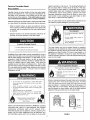
Property Damage Hazard
• AIIwater heaters eventually leak
• Do notinstall without adequate drainage
Installation of the water heater must be accomplished in such a
manner that if the tank or any connections should leak, the flow
will not cause damage to the structure. For this reason, it is not
advisable to install the water heater in an attic or upper floor.
When such locations cannot be avoided, a suitable drain pan
should be installed under the water heater. Drain pans are
available at your local Sears or hardware store. Such a drain
pan must have a minimum length and width of at least 2 inches
(51 mm) greater that the water heater dimensions and must be
piped to an adequate drain. The pan must not restrict
combustion air flow.
Fire or Explosion Hazard
heater's pilot light or main burner. The resulting flashback and
fire can cause death or serious burns to anyone in the area.
Even though this water heater is a flammable vapors ignition
resistant water heater and is designed to reduce the chances
of flammable vapors being ignited, gasoline and other
flammable substances should never be stored or used in the
same vicinity or area containing a gas water heater or other
open flame or spark producing appliance.
Also, the water heater must be located and/or protected so it is
not subject to physical damage by a moving vehicle.
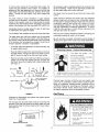
Fire Hazard
For continued protection against
riskof fire:
,Do not instalJ water heater on
carpeted floo_
.Do not operate water heater if
flood damaged.
This water heater must not be installed directly on carpeting.
Carpeting must be protected by metal or wood panel beneath
the appliance extending beyond the full width and depth of the
appliance by at least 3 inches (76.2 mm) in any direction, or if
the appliance is installed in an alcove or closet, the entire floor
must be covered by the panel. Failure to heed this warning may
result in a fire hazard.
Fire or Explosion Hazard
using or sewJcing water heater.
• Improper use may result in fire or
explosion
• Maintan required clearances to
combustibles.
" Do not store or use gasoline or other flammable
vapors and liquids in the vicinity of this or any other
app))ance
Avod all ignition sources if you smell LP gas.
* Do not expose water heater centre1to excessive gas
pressure
. Useonly gas shown on rating pJate.
. Maintain required clearances to combustibles
. Keep ignition sources away from faucets after
,. extended period ofnon use
Read instruction manual before
_ installing, using or servicing ._,d(
_' water heater
INSTALLATIONS IN AREAS WHERE FLAMMABLE LIQUIDS
(VAPORS) ARE LIKELY TO BE PRESENT OR STORED
(GARAGES, STORAGE AND UTILITY AREAS, ETC.):
Flammable liquids (such as gasoline, solvents, propane [LP or
butane, etc.] and other substances such as adhesives, etc.)
emit flammable vapors which can be ignited by a gas water
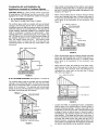
Minimum clearances between the water heater and combustible
construction are 0 inch at the sides and rear, 4 inches
(102 mm) at the front, and 6 inches (153 ram) from the vent
pipe, see Figure 8. Clearance from the top of the jacket is 12
inches (305 mm) on most models. Note that a lesser dimension
may be allowed on some models, refer to the label attached
adjacent to the gas control valve on the water heater.
TOP VIEW TOP VIEW
OF CLOSET OF CLOSET
WITHOUT DOOR WITH DOOR
O" MIN O" MIN.
0" I_IN, 4" MIN,
S" MIN,
FIGURE8.
9

Breathing Hazard - Carbon Monoxide Gas
S
Install water heater in accordance
with the instruction manual and
NFPA 54.
To avoid injury, combustion and
ventilation air must be taken from
outdoors.
Do not place chemical vapor
emitting products near water
heater.
Breathingcarbonmonoxidecancausebrain damageor
death. Always read and understandinstructionmanual
A gas water heater cannot operate properly without the correct
amount of air for combustion, see Figure 9. Do not install in a
confined area such as a closet, unless you provide air as shown
in the Locating The New Water Heater section. Never obstruct
the flow of ventilation air. If you have any doubts or questions at
all, call your gas supplier. Failure to provide the proper amount
of combustion air can result in a fire or explosion and cause
death, serious bodily injury, or property damage.
12" MAX. (305 mr¢
1
VENTILATION
AIR
OPENING O
{
13Q5mini
FRONTVIEW _
OFDOOR
AIR DUCT
FIGURE9.
If this water heater will be used in beauty shops, barber shops,
cleaning establishments, or self-service laundries with dry
cleaning equipment, it is imperative that the water heater or
water heaters be installed so that combustion and ventilation
air be taken from outside these areas.
Propellants of aerosol sprays and volatile compounds,
(cleaners, chlorine based chemicals, refrigerants, etc.) in
addition to being highly flammable in many cases, will also
change to corrosive hydrochloric acid when exposed to the
combustion products of the water heater. The results can be
hazardous, and also cause product failure.
Insulation Blankets
Insulation blankets available to the general public for external
use on gas water heaters are not necessary with Kenmore
products. The purpose of an insulation blanket is to reduce the
standby heat loss encountered with storage tank heaters, Your
Kenmore water heater meets or exceeds the National Appliance
Energy Conservation Act standards with respect to insulation
and standby loss requirements, making an insulation blanket
unnecessary.
Breathing Hazard - Carbon Monoxide Gas
.... . :-'._,., • Do not obstruct water heater air
_'¢:S. intake with insulating blanket.
i_i',"_i" • Gas and carbon monoxide
• detectors are available,
_ _ lni_thal_-Wltne.rthe(?_erinmaCCa°_dance
Breathing carbon monoxide can cause brain damage or
death. Always read and understand instruction manual
_i& WARNING
Should you choose to apply an insulation blanket to this heater,
you should follow these instructions (See Figure 1 for
identification of components mentioned below). Failure to follow
these instructions can restrict the air flow required for proper
combustion, potentially resulting in fire, asphyxiation, serious
personal injury or death.
Do not apply insulation to the top of the water heater, as this
will interfere with safe operation of the draft hood.
Do not cover the outer door, thermostat or temperature &
pressure relief valve.
Do not allow insulation to come within 2" (50.8 mm) of the
floor to prevent blockage of combustion air flow to the burner.
Do not cover the instruction manual. Keep it on the side of
the water heater or nearby for future reference.
Do obtain new warning and instruction labels from Sears
for placement on the blanket directly over the existing labels.
Do inspect the insulation blanket frequently to make certain
it does not sag, thereby obstructing combustion air flow.
10
Combustion Air and Ventilation for
Appliances Located in Unconfined Spaces
UNCONFINED SPACE is space whose volume is not less than
50 cubic feet per 1,000 Btu per hour (4.8 m3 per kW) of the
aggregate input rating of all appliances installed in that space.
Rooms communicating directly with the space in which the
appliances are installed, through openings not furnished with
doors, are considered a part of the unconfined space.
In unconfined spaces in buildings, infiltration may be adequate
to provide air for combustion, ventilation and dilution of flue
gases. However, in buildings of tight construction (for example,
weather stripping, heavily insulated, caulked, vapor barrier, etc.),
additional air may need to be provided using the methods
described in Combustion Air and Ventilation for Appliances
Located in Confined Spaces.

Combustion Air and Ventilation for
Appliances Located in Confined Spaces
CONFINED SPACE is a space whose volume is less than
50 cubic feet per 1,000 Btu per hour (4.8 m3 per kW) of the
aggregate input rating of all appliances installed in that space.
A. ALL AIR FROM INSIDE BUILDINGS:
(See Figure 9 on page 9 and Figure 10 below)
The confined space shah be provided with two permanent
openings communicating directly with an additional room(s)
of sufficient volume so that the combined volume of all spaces
meets the criteria for an unconfined space. The total input of
all gas utilization equipment installed in the combined space
shall be considered in making this determination. Each
opening shall have a minimum free area of one square inch
per 1,000 Btu per hour (22 cm_/kW) of the total input rating of all
gas utilization equipment in the confined space, but not less
than 100 square inches (645 cm2). One opening shall
commence within 12 inches (30 cm) of the top and one
commencing within 12 inches (30 cm) of the bottom of the
enclosures.
NT
FURN__=_ NG
FIGURE10.
B. ALL AIR FROM OUTDOORS: (See Figures 9, 11,12 and 13)
The confined space shall be provided with two permanent
openings, one commencing within 12 inches (30 cm) of the
top and one commencing within 12 inches (30 cm) from the
bottom of the enclosure. The openings shall communicate
directly, or by ducts, with the outdoors or spaces (crawl or attic)
that freely communicate with the outdoors.
CHIMNEY OR
GAS VENT
VEN] ILATION LOUVERS
IEACH END OF ATTIC)
When directly communicating with the oL_doors, each opening
shall have a minimum free area of 1 square inch per 4,000 Btu
per hour (5.5 cm2/kW) of total input rating of all equipment in the
enclosure, see Figure 12.
When communicating with the outdoors through vertical
ducts, each opening shall have a minimum free area of
1 square inch per 4,000 BTU per hour (5.5 cm2/kW) of total
input rating of aH equipment in the enclosure, see
Figure 12.
VENTILATION LOUVERS
FURNACE
INLET AIR DUCT
(ENOS 1' OR 30 cm
ABOVE FLOOR)
FIGURE12.
When communicating with the outdoors through horizontal
ducts, each opening shall have a minimum free area of 1
square inch per 2,000 BTU per hour (11 cm2/kW) of total
input rating of aH equipment in the enclosure, see
Figure 13.
When ducts are used, they shall be of the same cross-
sectional area as the free area of the openings to which
they connect. The minimum short side dimension of
rectangular air ducts shall not be less than 3 inches
(76.2 mm), see Figure 13.
____ CHIMNEY OR GAS VENT
OUTLET AIR DUCT
iNLET AIR DUCT
FIGURE 13.
OUTLET AIR
WATER HEATER
FURNACE
INLET AIR DUCT
ALT. INLET AIR VENTII ATION LOUVERS
FIGUREll.
11
Louvers and Grilles: in calculating free area, considerafion
shall be given to the blocking effect of louvers, grilles or
screens protecting openings. Screens used shall not be
smaller than 1/4 inch (6.4 mm) mesh. Ifthe free area through
a design of louver or grille is known, it should be used in
calculating the size opening required to provide the free
area specified. If the design and free area is not known, it
may be assumed that wood louvers will be 20-25 percent
free area and metal louvers and grilles will have 60-75
percent free area. Louvers and grilles shall be fixed in the
open position or interlocked with the equipment so that they
are opened automatically during equipment operation.

• Special Conditions Created by Mechanical Exhausting or
Fireplaces: operation of exhaust fans, ventilation systems,
clothes dryers or fireplaces may create conditions requiring
special attention to avoid unsatisfactory operation of installed
gas utilization equipment.
Water Piping
Water temperature over 125°F
(52°C) car cause severe burns
instantly resulting in severe injury
or death.
Children, elderly, and the
physically or mentally disabled
are at hghest risk_or scald injury
Feel water before bathing or
showering.
Temperature limitr_g valves are
available.
Read instruction manuaJ for safe
temperature setting
HOTTER WATER CAN SCALD:
Water heaters are intended to produce hot water. Water heated
to a temperature which will satisfy space heating, clothes
washing, dish washing, cleaning and other sanitizing needs
can scald and permanently injure you upon contact. Some
people are more likely to be permanently injured by hot water
than others. These include the elderly, children, the infirm, or
physically/mentally handicapped. If anyone using hot water in
your home fits into one of these groups or if there is a local
code or state law requiring a certain temperature water at the
hot water tap, then you must take special precautions. In
addition to using the lowest possible temperature setting that
satisfies your hot water needs, a means such as a *mixing
valve, shall be used at the hot water taps used by these people
or at the water heater. Mixing valves are available at plumbing
supply or hardware stores, see Figure 14 below. Valves for
reducing point of use temperature by mixing cold and hot water
are also available. Follow manufacturer's instructions for
installation of the valves. Before changing the factory setting
on the thermostat, read the Temperature Regulation section in
this manual.
HOT WATER
OUTLET
*MIXiN
VALVE
COLD WATER
, INLET
,OCeLOWATE
INLET ON
FROM WATER HEATER
HOT WATER
OUTLET ON
WATER HEATER
FIGURE14.
Toxic Chemical Hazard
• Do notconnectto non-potablewater system.
This water heater shall not be connected to any heating systems
or component(s) used with a non-potable water heating
appliance.
All piping components connected to this unit for space heating
applications shall be suitable for use with potable water.
Toxic chemicals, such as those used for boiler treatment shall
not be introduced into this system.
Water supply systems may, because of such events as high
line pressure, frequent cut-offs or the effects of water hammer
among others, have installed devices such as pressure
reducing valves, check valves, back flow preventers, etc. to
control these types of problems. When these devices are not
equipped with an internal by-pass, and no other measures are
taken, the devices cause the water system to be closed. As
water is heated, it expands (thermal expansion) and closed
systems do not allow for the expansion of heated water.
The water within the water heater tank expands as it is heated
and increases the pressure of the water system. Ifthe relieving
point of the water heater's temperature-pressure relief valve is
reached, the valve will relieve the excess pressure. The
temperature-pressure relief valve is not intended for the
constant relief of thermal expansion. This is an unacceptable
condition and must be corrected, It is recommended that any
devices installed which could create a closed system have a
by-pass and/or the system have an expansion tank to relieve
the pressure built by thermal expansion in the water system.
Refer to the Thermal Expansion section under Troubleshooting
Guide or contact local plumbing authority or local Sears Service
Center on how to control this situation.
NOTE: To protect against untimely corrosion of hot and cold
water fittings, it is strongly recommended that di-electric
unions or couplings be installed on this water heater when
connected to copper pipe.
Property Damage Hazard
• Avoid water heater damage.
• Install thermal expansion tank if necessary.
• Do not apply heat to cold water inlet.
• Contact qualified insta/ier or Sears Service Center
12
Figure 15 shows the typical attachment of the water piping to
the water heater. The water heater is equipped with 3/4" NPT
water connections.
NOTE: if using copper tubing, solder tubing to an adapter
before attaching the adapter to the cold water inlet
connection. Do not solder the cold water supply line directly
to the cold water inlet. It will harm the dip tube and damage
the tank.
• Look at the top cover of the water heater. The water outlet is
marked "HOT". Put two or three turns of teflon tape around
the threaded end of the threaded-to-sweat coupling and
around both ends of the 3/4" NPT threaded nipple. Using
flexible connectors, connect the hot water pipe to the hot
water outlet on the water heater.

Lookatthetopofthewaterheater.Thecoldwaterinletis
marked "COLD". Put two or three turns of teflon tape around
the threaded end of the threaded-to-sweat coupling and
around both ends of the 3/4" NPT threaded nipple. Using
flexible connectors, connect the cold water pipe to the cold
water inlet of the water heater.
NOTE: This water heater is super insulated to minimize
heat loss from the tank. Further reduction in heat loss
can be accomplished by insulating the hot water lines
from the water heater.
INSTALLATIONCOMPLETED USING
INSTALLATION KIT
FLEXIBLE
WATER
CONNECTORS
HOT
e/A ITR-- COLe WATER
OUTLE _'_ INLET
N t
COUPLING _ COUPLING
DRAFT HGOD
TEr_IPERATURE -
_'-_- PRESSURE
RELIEF VALVE
DISCHARGE PIPE
(Do }lot c_p or plug)
%.
AIR
GAP
FLOORDRAIN
FIGURE15.
Temperature-Pressure Relief Valve
This heater is provided with a properly certified combination
temperature - pressure relief valve by the manufacturer.
The valve is certified by a nationally recognized testing
laboratory that maintains periodic inspection of production of
listed equipment of materials as meeting the requirements for
Relief Valves and Automatic Gas Shut-off Devices for Hot Water
Supply Systems, ANSI Z21.22 and the code requirements of
ASME.
If replaced, the valve must meet the requirements of local
codes, but not less than a combination temperature and
pressure relief valve certified as indicated in the above
paragraph.
The valve must be marked with a maximum set pressure not to
exceed the marked hydrostatic working pressure of the water
heater (150 psi = 1,035kPa) and a discharge capacity not less
than the water heater input rate as shown on the model rating
plate.
For safe operation of the water heater, the relief valve must not
be removed from its designated opening nor plugged.
The temperature-pressure relief valve must be installed directly
into the fitting of the water heater designed for the relief valve.
Position the valve downward and provide tubing so that any
discharge will exit only within 6 inches (153 mm) above, or at
any distance below the structural floor, see Figure 16. Be certain
that no contact is made with any live electrical part. The
discharge opening must not be blocked or reduced in size
under any circumstances. Excessive length, over 30 feet
(9.14 m), or use of more than four elbows can cause restriction
and reduce the discharge capacity of the valve.
No valve or other obstruction is to be placed between the relief
valve and the tank. Do not connect tubing directly to discharge
drain unless a 6 inch air gap is provided. To prevent bodily
injury, hazard to life, or property damage, the relief valve must
be allowed to discharge water in quantities should
circumstances demand. If the discharge pipe is not connected
to a drain or other suitable means, the water flow may cause
property damage.
Water Damage Hazard
• Temperature-pressure relief valve discharge
pipe must terminate at adequate drain•
! •
• ,L_ ,
Explosion Hazard
Temperature-pressure relief valve
must comply with ANSI Z21.22
and ASME code•
Properly sized temperature-
pressure relief valve must be
installed in opening provided.
Can result in overheating and
excessive tank pressure.
Can cause serious injury or death.
13
The Discharge Pipe:
• Shall not be smaller in size than the outlet pipe size of the
valve, or have any reducing couplings or other restrictions.
• Shall not be plugged or blocked.
• Shall be of material listed for hot water distribution.
• Shall be installed so as to allow complete drainage of both
the temperature-pressure relief valve, and the discharge
pipe.
• Shall terminate at an adequate drain.
• Shall not have any valve between the relief valve and tank.

Watertemperatureover125°F
(52°C)cancausesevereburns
instantlyresultinginsevereinjury
ordeath
Children,the elderly,andthe
physicallyor mentallydisabled
areathighestriskforscaldinjury.
Fee/waterbeforebathingor
showering
Temperaturelimitingvalvesare
available
Readinstructonmanualforsafe
temperaturesetting
Thetemperature-pressurereliefvalvemustbemanually
operatedatleastonceayear.Cautionshouldbetakento
ensurethat(1)nooneisinfrontoforaroundtheoutletofthe
temperature-pressurereliefvalvedischargeline,and(2)the
watermanuallydischargedwillnotcauseanybodilyinjuryor
propertydamagebecausethewatermaybeextremelyhot.
Ifaftermanuallyoperatingthevalve,itfailstocompletelyreset
andcontinuestoreleasewater,immediatelyclosethecold
waterinlettothewaterheater,followthedraininginstructions,
andreplacethetemperature-pressurereliefvalvewithanew
one.
HOT WATER
OUTLET COLD WATER
_l INLET
\
SHUTOFF
VALVE
DRAFT NeOD
TEMPERATURE PRESSU RE
RELIEF VALVE
(OPTIONAL TOP T & P RELIEF
VALVE NOT SHOWN}
Never use this water heater unless it is completely full of water.
To prevent damage to the tank, the tank must be filled with
water. Water must flow from the hot water faucet before turning
"ON" gas to the water heater.
To fill the water heater with water:
• Close the water heater drain valve by turning the handle to
the right (clockwise). The drain valve is on the lower front of
the water heater.
• Open the cold water supply valve to the water heater.
NOTE: The cold water supply valve must be left open when
the water heater is in use.
To insure complete filling of the tank, allow air to exit by
opening the nearest hot water faucet. Allow water to run
until a constant flow is obtained. This will let air out of the
water heater and the piping.
• Check all water piping and connections for leaks. Repair
as needed.
Venting
Breathing Hazard - Carbon Monoxide Gas
• Vent dampers must be certified
ir_accordance with ANSI Z21 68
• Vent damper must permit proper
drafting ofwater heater.
•.::.'_:._ t_':.:,, • InstallproperJysizedventing.
_i_.i_!:_.ii:._;:_:4:':_[:"_'¢:_:LE"_" outdoors.D°not install without venting
• De not install without drafthood.
_..a_._t_ _ _,. • If common vented h_stall in
I11 accordance with NFPA 54
" * Be afar for obstructed or deterio-
rated vent system to avoid
serious injury or death
Breathing carbon mono×ide can cause brain damage or
death Always read and understand nstruction manual
D!SHCARGE PIPE
FIGURE16.
Filling the Water Heater
Property Damage Hazard
. Avoid water heater damage.
. Fill tank with water before operating
VENT DAMPERS - Any vent damper, whether it is operated
thermally or otherwise must be removed if its use inhibits proper
drafting of the water heater.
Thermally Operated Vent Dampers: Gas-fired water heaters
having thermal efficiency in excess of 80% may produce a
relatively low flue gas temperature. Such temperatures may
not be high enough to properly open thermally operated vent
dampers. This would cause spillage of the flue gases and
may cause carbon monoxide poisoning.
14
Vent dampers must bear evidence of certification as complying
with the current edition of the American National Standard
ANSI Z21.68 (ANSI Z21.66 & 67, respectively, cover electrically
and mechanically actuated vent dampers). Before installation
of any vent damper, consult your local Sears Service Center or
the local gas supplier for further information.

Toinsureproperventingofthisgas-firedwaterheater,the
correctventpipediametermustbeutilized,Anyadditionsor
deletionsofothergasappliancesonacommonventwiththis
waterheatermayadverselyaffecttheoperationofthewater
heater.Consultyourgassupplierifanysuchchangesare
planned.
Forproperventingincertaininstallations,a largerdiameter
ventpipemaybenecessary,ConsultyourlocalSearsService
Centerorgassuppliertoaidyouindeterminingtheproper
ventingforyourwaterheaterfromtheventtablesinthecurrent
editionoftheNationalFuelGasCodeANStZ223,1/NFPA54,
Periodicallychecktheventingsystemforsignsofobstruction
ordeteriorationandreplaceifneeded,
Thecombustionandventilationairflowmustnotbeobstructed,
Thewaterheaterwithdrafthoodinstalledmustbeconnected
toachimneyorlistedventpipesystem,whichterminatesto
theoutdoors,Neveroperatethewaterheaterunlessitisvented
totheoutdoorsandhasadequateairsupplytoavoidrisksof
improperoperation,explosionorasphyxiation,
Forproperdrafthoodattachment,thedrafthoodlegsmay
beangledslightlyinward,
Placethedrafthoodlegsinthereceivingholesonthetopof
thewaterheater.Thelegswillsnapintheholestogivea
tightfit.Securetwolegstotopwithsheetmetalscrews,
Placetheventpipeoverthedrafthood,Withtheventpipein
position,drillasmallholethroughboththeventpipeand
drafthood,Securethemtogetherwithasheetmetalscrew,
seeFigure17.
DRAFT HOOD _V VENT $
DRAFT HOOD
All vent gases must be completely vented to the outdoors of the
structure (dwelling), Install only the draft hood provided with
the new water heater and no other draft hoed.
Vent pipes must be secured at each joint with sheet metal
screws,
There must be a minimum of 6 inches (153 mm) clearance
between single wall vent pipe and any combustible material.
Fill and seal any clearance between single wall vent pipe and
combustible material with mortar mix, cement, or other
noncombustible substance, For other than single wall, follow
vent pipe manufacturer's clearance specifications, To insure
a tight fit of the vent pipe in a brick chimney, seal around the
vent pipe with mortar mix cement,
Failure to have required clearances between vent piping and
combustible material will result in a fire hazard,
Be sure vent pipe is propedy connected to prevent escape of
dangerous flue gases which could cause deadly asphyxiation.
• Flue gases may escape if vent
p_peis not connected
• Do not store corrosive chemicals
in vicini_ ofwater heater,
• Chemical corrosion of flue and
vent system can cause serious
injuryor death.
• Contact a qualified installer or
service agency
Breathing carbon monoxide can cause brain damage
ordeath Always read and understand instruction manual.
OP,AFT HOOD
VENT TO OUTDOORS
INEY
Chemical vapor corrosion of the flue and vent system may
occur if air for combustion contains certain chemical vapors.
Spray can propellants, cleaning solvents, refrigerator and air
conditioner refrigerants, swimming pool chemicals, calcium
and sodium chloride, waxes, bleach and process chemicals
are typical compounds which are potentially corrosive.
FIGURE17.
Obstructed or deteriorated vent systems may present serious
health risk or asphyxiation.
The vent pipe from the water heater must be no less than the
diameter of the draft hood outlet on the water heater and must
slope upward at least 1/4 inch per linear foot (21 mm per meter),
see Figure 18,
CHfMNEY
Gas Piping
Fire and Explosion Hazard
• Do not use water heater with
any gas other than the gas
shown on the rating plate
, E×cessve pressure to gas
control valve can cause serious
injury or death
, Turn off gas lines during
installation
, Contact qualified installer or
service agency
FIGURE18.
15

Makesurethegassuppliedisthesametypelistedonthe
modelratingplate.Theinletgaspressuremustnotexceed
14inchwatercolumn(3.5kPa)fornaturalandpropanegas
(L,R),Theminimuminletgaspressurelistedontherating
plateisforthepurposeofinputadjustment.Ifthegascontrol
valveissubjectedtopressuresexceeding1/2poundpersquare
inch(3,5kPa),thedamagetothegascontrolvalvecouldresult
inafireorexplosionfromleakinggas,
Ifthemaingaslineshut-offservingallgasappliancesisused,
alsoturn"OFF"thegasateachappliance,Leaveallgas
appliancesshut"OFF"untilthewaterheaterinstallationis
complete,
Agaslineofsufficientsizemustberuntothewaterheater,
Consultthecurrentedition of National Fuel Gas Code ANSI
Z223.1/NFPA 54 and your gas supplier concerning pipe size.
There must be:
in improper and inefficient operation of the appliance, producing
carbon monoxide gas in excess of safe limits, which could
result in serious injury or death, Contact your local Sears Service
Center or local gas supplier for any specific changes which
may be required in your area,
W!'lvA%'!rJ II
Fire and Explosion Hazard
. Use joint compound or tape
cornpatible with propane
. Leak test before operating
heater
• Disconnect gas p!ping and
shut-off valve before pressure
testing system
• A readily accessible manual shut off valve in the gas supply
line serving the water heater, and
• A drip leg (sediment trap) ahead of the gas control valve to
help prevent dirt and foreign materials from entering the
gas control valve.
• A flexible gas connector or a ground joint union between the
shut off valve and control valve to permit servicing of the unit.
Be sure to check all the gas piping for leaks before lighting the
water heater. Use a soapy water solution, not a match or open
flame. Rinse off soapy solution and wipe dry.
The minimum inlet gas pressure shown on the rating plate is
that which will permit firing at the rated input.
Breathing Hazard - Carbon Monoxide Gas
:4:(... • High altitude orifice must be installed
foroparot onsbave3,S00i ,006rn/
,=,,:>_ ,_!:_ or 5,500 ft (1,676 m) for a high altitude
models.
_ _ _ • Contact a qualifed installer or service
i,
agency.
Breathing carbon monoxide can cause brain damage or
death Always read and understand instruction manual
If a standard model is installed above 3,300 feet (1,006 m) or a
high altitude model is installed above 5,500 feet (1,676 m) the
input rating should be reduced at the rate of 4 percent for each
1,000 feet (305 m ) above sea level which requires replacement
of the burner orifice in accordance with National Fuel Gas Code
ANSI Z223.1IN FPA 54. Contact your local Sears Service Center
or local gas supplier for further information.
Failure to replace the standard orifice with a high altitude orifice
when installed at elevations above 3,300 feet (1,006 m) or
above 5,500 feet (1,676 m) for high altitude model) could result
Use pipe joint compound or teflon tape marked as being
resistant to the action of petroleum (Propane [L,R]) gases.
The appliance and its gas connection must be leak tested
before placing the appliance in operation.
The appliance and its individual shut-off valve shall be
disconnected from the gas supply piping system during any
pressure testing of that system at test pressures in excess of
1/2 pound per square inch (3.5kPa). It shall be isolated from
the gas supply piping system by closing its individual manual
shut-off valve during any pressure testing of the gas supply
piping system at test pressures equal to or less than 1/2 pound
per square inch (3.5kPa).
Connecting the gas piping to the gas control valve of the water
heater can be accomplished by either of the two methods
shown in Figures 19 and 20.
Sediment Traps
16
Fire and Explosion Hazard
• Contaminants in gas lines can
cause fire or explosion.
• Clean all gas piping before
installation.
• Install drip leg in accordance
with NFPA 54,
Contaminants in the gas lines may cause improper operation
of the gas control valve that may result in fire or explosion.
Before attaching the gas line be sure that all gas pipe is clean
on the inside. To trap any dirt or foreign material in the gas
supply line, a drip leg (sometimes called a sediment trap)
must be incorporated in the piping. The drip leg must be readily
accessible. Install in accordance with the Gas Piping section.
Refer to the current edition of the National Fuel Gas Code,
ANSI Z223.1/NFPA 54.

GROUND JOINT
UNION
{OPTIONAL)
GASCONTROL
VALVE
_])_ DRIP LEG
3" MIN. (SEDIMENT TRAP)
(76=2 m
FIGURE19. GAS PIPINGWITH FLEXIBLECONNECTOR.
A sediment trap shall be installed as close to the inlet of the
water heater as practical at the time of water heater installation.
The sediment trap shall be either a tee fitting with a capped
nipple in the bottom outlet or other device recognized as an
effective sediment trap. If a tee fitting is used, it shall be installed
in conformance with one of the methods of installation, shown
in Figures 19 and 20.
eROtJNn JOINT _ _ BLA)K PIPEj{_
UNION BLACK PIPE
(OPTIONAL)
_ GAS
CONTROL
VALVE
3" MIN,
(76,_ m
FIGURE 20. GAS PIPING WITH ALL
BLACK IRON PIPE TO GAS CONTROL.
17

FOR YOUR SAFETY READ BEFORE LIGHTING
";:O;::no::m:oe :rreO:so''o
BEFORE OPERATING: ENTIRE SYSTEM MUST BE FILLED WITH WATER AND AIR PURGED FROM ALL LINES.
A. This appliance hasa pilotwhichmust belighted byhand.
When lighting the pilot, followthese instructions exactly.
If you cannot reach your gas supplier, call the fire
department.
B. BEFORE LIGHTING smellall aroundtheappliance area
for gas. Be sure tosmell next tothe floor because some
gas is heavier than air and will settle on the fleer.
WHATTO DO IFYOU SMELL GAS:
Do not try to lightany appliance.
Do not touch any electric switch; do notuse any phone
inyour building.
Immediately call your gas supplier from a neighbor's
phone. Follow the gas supplier's instructions.
C
D
Use only your hand to pushin or turn the gas control
knob. Never use tools.Ifthe knob will net push in or turn
by hand, don't try to repair it, call a qualified service
technician. Force or attempted repairmay resultin afire
or explosion.
Do not use this appliance if any part has been under
water. Immediately call aqualified service technician to
inspect the appliance and to replace any part of the
control system and any gas control which has been
under water.
LIGHTING INSTRUCTIONS
_.. GASCONTROL KNOB
IGNITOR
GENERATOR
THERMOSTAT
DIAL
GAS CONTROL
FIGURE *'A" F]GURJE "B '_ FIGURE "G"
"OFF POGIT!ON "PILOT" PO_ITION "ON" POSITION
TOPKNOB
MAIN BURNER
/
FIGURE "D"
1. _'_ STOP! Readthesafetyinformation
_.I above on this label.
2. Set the thermostat to lowest setting (PILOT SETTING).
Turn thermostat dial fully clockwise f_ until itstops.
3. Pushthegas control knobdown slightlyand turnclockwise
f_ to"OFF", SEE FIGURE "A".
NOTE: Knob CANNOT beturned from "PILOT" to"OFF"
unless it is pushed down slightly. Do not force.
4. Remove the outer burner door located below the gas
control.
5. Wait five (5) minutes to clear out any gas. If you then
smell gas,(_) STOP! Follow"B" in the safetyinformation
above on thislabel. Ifyou don't smellgas, goto next step.
6. This unit isequipped with a pushbutton pilot ignitor,which
is used to light the pilot. Locate the ignitor on the gas
control.
7. Turn gas control knob counterclockwise _ to "PILOT",
SEEFIGURE "B".
8. The pilotis locatedon the rightside ofthe burner.Itcan be
located by looking through the glass view port while
pressing the pieze ignitor button several times. Lookfora
spark atthe pilotlocation, FIGURE"D".
9. Once the pilot has been found, push the gas knob all the
way down. Immediately pressthe pilot ignitorbutton rapidly
(4) to (5) times. If the pilot will net light, repeat step (3)
through (9).
10. Continue to hold the gas control knob down for about one
(1) minute after the pilot is lit. Release the gas control knob
andit will pep back up. Pilot should remain lit.Ifitgoes out,
repeat step (3) through (9). Itmay take several minutes for
air to clearthe lines before the pilot will light.
If knob does not pop up when released, stop and
immediately call your service technician or gas supplier.
If the pilot will not stay lit after several tries, turn the gas
control knob clockwise f'_ to "OFF" and call your service
technician orgas supplier. SEE FIGURE"A".
11. Once the pilotflame isestablishedreplacethe euter bumer
door.
12. At arms length away, turn gas control knob
counterclockwise _ to"ON". SEE FIGURE"C".
13. Set thermostat todesired setting.
DANGER: Hotter water increases the risk of
scald injury. Consult the instruction manual
before changing temperature.
TO TURN OFF GAS TO APPLIANCE
1. Setthermostattothelowestsetting(PILOTLIGHTING). 2. Pushgascontrelknobdownslightlyandtumclockwiset"=_ to "OFF". Do not force. SEE FIGURE 'W'.
18

Temperature Regulation
Due to the nature of the typical gas water heater, the water
temperature in certain situations may vary up to 30F° (16.7 C°)
higher or lower at the point of use such as, bathtubs, showers,
sink, etc.
Any water heater's intended purpose is to heat water. Hot
water is needed for cleansing, cleaning, and sanitizing (bodies,
dishes, clothing). Untempered hot water can present a scald
hazard. Depending on the time element, and the people
involved (adults, children, elderly, infirm, etc.) scalding may occur
at different temperatures.
Water temperature over 125°F
(52°0) can cause severe burns
instantly resulting in severe injury
or death.
Children, the elderly, and the
physically or mentally disabled
are at highest risk for scald injury
Feel water before bathing or
showering.
Temperature limiting valves are
available
Read instruction manual for safe
temperature setting
HOTTER WATER CAN SCALD: Water heaters are intended to
produce hot water. Water heated to a temperature which will
satisfy space heating, clothes washing, dish washing, and
other sanitizing needs can scald and permanently injure you
upon contact. Some people are more likely to be permanently
injured by hot water than others. These include the elderly,
children, the infirm, or physically/mentally handicapped. If
anyone using hot water in your home fits into one of these
groups or if there is a local code or state law requiring a certain
temperature water at the hot water tap, then you must take
special precautions. In addition to using the lowest possible
temperature setting that satisfies your hot water needs, a
means such as a mixing valve, shall be used at the hot water
taps used by these people or at the water heater. Mixing valves
are available at plumbing supply or hardware stores. Follow
manufacturer's instructions for installation of the valves. Before
changing the factory setting on the thermostat, read the
Temperature Regulation section in this manual, see Figures
21 and 22.
Never allow small children to use a hot water tap, or to draw
their own bath water. Never leave a child or handicapped person
unattended in a bathtub or shower.
NOTE: A water temperature range of120°F-140°F (49°C-60°C)
is recommended by most dishwasher manufacturers.
The thermostat of this water heater has been factory set at its
lowest position. It is adjustable and must be reset to the
desired temperature setting to reduce the risk of scald injury.
The mark (A) indicative of approximately 120°F (49°0) is
preferred starting point. Some states have a requirement for a
lower setting.
Turn the water temperature dial clockwise ( f'_ ) to decrease
the temperature, or counterclockwise (('_) to increase the
temperature.
Should overheating occur or the gas supply fail to shut off, turn
off the manual gas control valve to the appliance.
- GAB CONTROL KNOB
_i PIEZo
IGNITOR
GENERATOR
THERMOSTAT
DiAL
FIGURE21.
l
VERYHOT=approx.160°F(71°C)
C = approx. 150°F (66°0)
B= approx. 140°F(60°C)
A = approx. 130°F (54°C)
A = approx. 120°F (49°C)
LOW = approx. 80°F (27°C)
FIGURE22.
About 1/2 second
About 1-1/2 seconds
Less than 5 seconds
About 30 seconds
More than 5 minutes
19

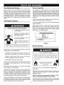
Tank (Sediment) Cleaning
Sediment build-up on the tank bottom may create varying
amount of noise, and if left in the tank will cause permanent
tank failure, tn some water areas, you may not be able to drain
all sediment deposits by simply draining the tank. In these
cases Mag-Erad (part no. 23600) can be used to help remove
the sediment deposits. This may be ordered from the Sears
Service Center. For ordering, refer to the Parts Order List
section.
Vent System Inspection
Burner Inspection
Carbon Monoxide and Fire Hazard
• Flue gases may escape if vent pipe
is not connected.
• Be alert for obstructed, sooted or
deterioratedventsystemtoavo,d
serious injury or death.
;;_:('> • Do not store corrosive chemicals
!
:' _ Chemical corrosion of flue and vent
• in vicinity of water heater.
system can cause serious injury or
death
Breathing carbon monoxide can cause brain damage or
death Always read and understand instruction manual
Flood damage to a water heater may not be readily visible or
immediately detectable. However, over a period of time a
flooded water heater will create dangerous conditions which
can cause DEATH, SERIOUS BODILY INJURY, OR PROPERTY
DAMAGE. Contact a Sears Service Center to replace a flooded
water heater. Do not attempt to repair the unit! It must be
replaced!
At least once a year a visual inspection should be made of the
main burner and pilot burner, see Figure 23.
You should check for sooting. Soot is not normal and will impair
proper combustion.
Soot build-up indicates a problem that requires correction
before further use. Turn "OFF" gas to water heater and
leave "OFF" until repairs are made, because failure to correct
the cause of the sooting can result in a fire causing death,
serious injury, or property damage.
FIGURE23.
Burner Cleaning
At least once a year a visual inspection should be made of the
venting system. You should look for:
• Obstructions which could cause improper venting. The
combustion and ventilation air flow must not be obstructed.
• Damage or deterioration which could cause improper
venting or leakage of combustion products.
• Rusted flakes around top of water heater.
Be sure the vent piping is properly connected to prevent escape
of dangerous flue gasses which could cause deadly
asphyxiation.
Obstructions and deteriorated vent systems may present
serious health risk or asphyxiation.
Chemical vapor corrosion of the flue and vent system may
occur if air for combustion contains certain chemical vapors.
Spray can propellants, cleaning solvents, refrigerator and air
conditioner refrigerants, swimming pool chemicals, calcium
and sodium chloride, waxes, bleach and process chemicals
are typical compounds which are potentially corrosive.
If when inspecting the vent system you find sooting or
deterioration, something is wrong. Call the local gas supplier
to correct the problem and clean or replace the flue and venting
before resuming operation of the water heater.
2O
Fire or Explosion Hazard
Failure to properly reseal the combustion chamber will
disable the flammable vapor _gnition resistance feature
ofthis water heater, which could result in death or serious
njury Contact your local Sears Service Center
for assistance
Read instruction manual before _._
installing, using or servicing ._,_lf"
water heater
In the event your burner needs cleaning, following these
instructions:
If inspection of the burner shows that cleaning is required, turn
the gas control knob clockwise ( f% ) to the "OFF" position,
depressing slightly.
NOTE: The knob cannot be turned from "PILOT" to "OFF"
unless knob is depressed slightly. DO NOT FORCE.
The burner needs to be removed for cleaning. Call the Sears
Service Center to remove and clean the burner and correct the
problem that required the burner to be cleaned.
Page is loading ...
Page is loading ...
Page is loading ...
Page is loading ...
Page is loading ...
Page is loading ...
Page is loading ...
Page is loading ...
Page is loading ...
Page is loading ...
Page is loading ...
Page is loading ...
-
 1
1
-
 2
2
-
 3
3
-
 4
4
-
 5
5
-
 6
6
-
 7
7
-
 8
8
-
 9
9
-
 10
10
-
 11
11
-
 12
12
-
 13
13
-
 14
14
-
 15
15
-
 16
16
-
 17
17
-
 18
18
-
 19
19
-
 20
20
-
 21
21
-
 22
22
-
 23
23
-
 24
24
-
 25
25
-
 26
26
-
 27
27
-
 28
28
-
 29
29
-
 30
30
-
 31
31
-
 32
32


Kenmore POWER MISER 153.33616 User manual
- Category
- Water heaters & boilers
- Type
- User manual
Ask a question and I''ll find the answer in the document
Finding information in a document is now easier with AI
Related papers
-
Kenmore 153.559400 User manual
-
-
Sears 761 User manual
-
-
-
-
-
Kenmore Gas Heater 153.33096 User manual
-
-
Other documents
-
American Water Heater VG6250T100 User manual
-
A.O. Smith G6-DMH4032NV User manual
-
Reliance Water Heaters 184333-001 User manual
-
State Industries Commercial Gas Water Heater User manual
-
-
 Falcon Stainless SWC1-18 User manual
-
Regency 600PHSHEATER 2.5 Gallon 120 Volt Water Heater User manual
-
 AHRI 154 Series Commercial Gas Water Heaters User manual
-
Rheem PROTECH SP14270H Operating instructions
-
AO Smith GCV40-200 Owner's manual

