Sony STR-DN1000 User manual

Category
AV receivers
Type
User manual
©2009 Sony Corporation
4-136-735-11(1)
Multi Channel AV
Receiver
Operating Instructions
STR-DN1000
2
US
To reduce the risk of fire or electric
shock, do not expose this apparatus to
rain or moisture.
To reduce the risk of fire, do not cover the
ventilation opening of the apparatus with
newspapers, tablecloths, curtains, etc.
Do not place the naked flame sources such as lighted
candles on the apparatus.
To reduce the risk of fire or electric shock, do not
expose this apparatus to dripping or splashing, and
do not place objects filled with liquids, such as
vases, on the apparatus.
Do not install the appliance in a confined space, such
as a bookcase or built-in cabinet.
As the main plug is used to disconnect the unit from
the mains, connect the unit to an easily accessible
AC outlet. Should you notice an abnormality in the
unit, disconnect the main plug from the AC outlet
immediately.
Do not expose batteries or apparatus with battery-
installed to excessive heat such as sunshine, fire or
the like.
The unit is not disconnected from the mains as long
as it is connected to the AC outlet, even if the unit
itself has been turned off.
Excessive sound pressure from earphones and
headphones can cause hearing loss.
For customers in the United
States and Canada
This symbol is intended to alert
the user to the presence of the Hot
Surface that may be hot if it is
touched during the normal
operation.
ENERGY STAR
®
is a U.S. registered
mark.
As an ENERGY STAR
®
partner, Sony
Corporation has determined that this
product meets the ENERGY STAR
®
guidelines for energy efficiency.
For customers in the United
States
Owner’s Record
The model and serial numbers are located on the rear
of the unit. Record these numbers in the space
provided below. Refer to them whenever you call
upon your Sony dealer regarding this product.
M o d e l N o . _____________________________________________________
S e r i a l N o . ______________________________________________________
This symbol is intended to alert the
user to the presence of uninsulated
“dangerous voltage” within the
product’s enclosure that may be of
sufficient magnitude to constitute a
risk of electric shock to persons.
This symbol is intended to alert the
user to the presence of important
operating and maintenance
(servicing) instructions in the
literature accompanying the
appliance.
Important Safety Instructions
1) Read these instructions.
2) Keep these instructions.
3) Heed all warnings.
4) Follow all instructions.
5) Do not use this apparatus near water.
6) Clean only with dry cloth.
7) Do not block any ventilation openings. Install in
accordance with the manufacturer’s instructions.
8) Do not install near any heat sources such as
radiators, heat registers, stoves, or other
apparatus (including amplifiers) that produce
heat.
9) Do not defeat the safety purpose of the polarized
or grounding-type plug. A polarized plug has
two blades with one wider than the other. A
grounding type plug has two blades and a third
grounding prong. The wide blade or the third
prong are provided for your safety. If the
provided plug does not fit into your outlet,
consult an electrician for replacement of the
obsolete outlet.
10)Protect the power cord from being walked on or
pinched particularly at plugs, convenience
receptacles, and the point where they exit from
the apparatus.
11)Only use attachments/accessories specified by
the manufacturer.
WARNING
3
US
12)Use only with the cart, stand, tripod, bracket, or
table specified by the manufacturer, or sold with
the apparatus. When a cart is used, use caution
when moving the cart/apparatus combination to
avoid injury from tip-over.
13)Unplug this apparatus during lightning storms or
when unused for long periods of time.
14)Refer all servicing to qualified service personnel.
Servicing is required when the apparatus has
been damaged in any way, such as power-supply
cord or plug is damaged, liquid has been spilled
or objects have fallen into the apparatus, the
apparatus has been exposed to rain or moisture,
does not operate normally, or has been dropped.
The following FCC statement
applies only to the version of
this model manufactured for
sale in the U.S.A. Other
versions may not comply with
FCC technical regulations.
NOTE:
This equipment has been tested and found to comply
with the limits for a Class B digital device, pursuant
to Part 15 of the FCC Rules. These limits are
designed to provide reasonable protection against
harmful interference in a residential installation.
This equipment generates, uses, and can radiate
radio frequency energy and, if not installed and used
in accordance with the instructions, may cause
harmful interference to radio communications.
However, there is no guarantee that interference will
not occur in a particular installation. If this
equipment does cause harmful interference to radio
or television reception, which can be determined by
turning the equipment off and on, the user is
encouraged to try to correct the interference by one
or more of the following measures:
Reorient or relocate the receiving antenna.
Increase the separation between the equipment
and receiver.
Connect the equipment into an outlet on a circuit
different from that to which the receiver is
connected.
Consult the dealer or an experienced radio/TV
technician for help.
CAUTION
You are cautioned that any changes or modification
not expressly approved in this manual could void
your authority to operate this equipment.
To reduce the risk of electric shock, the speaker cord
should be connected to the apparatus and the
speakers in accordance with the following
instructions.
1) Disconnect the AC power cord from the MAINS.
2) Strip 10 to 15 mm of the wire insulation of the
speaker cord.
3) Connect the speaker cord to the apparatus and
the speakers carefully so as not to touch the core
of speaker cord by hand. Also disconnect the AC
power cord from the MAINS before
disconnecting the speaker cord from the
apparatus and the speakers.
4
US
About This Manual
The instructions in this manual are for model
STR-DN1000. Check your model number by
looking at the lower right corner of the front panel.
In this manual, models of area code U is used for
illustration purposes unless stated otherwise. Any
difference in operation is clearly indicated in the
text, for example, “Models of area code CA only”.
The instructions in this manual describe the
controls on the supplied remote. You can also use
the controls on the receiver if they have the same
or similar names as those on the remote.
“Neural-THX” and “NEURAL-THX” introduced
in the Operating Instructions and displayed on the
GUI menu screen and on the display mean Neural-
THX Surround.
This receiver incorporates Dolby* Digital and Pro
Logic Surround and the DTS** Digital Surround
System.
* Manufactured under license from Dolby
Laboratories. Dolby and the double-D symbol
are trademarks of Dolby Laboratories.
** Manufactured under license under U.S. Patent
#’s: 5,451,942; 5,956,674; 5,974,380; 5,978,762;
6,226,616; 6,487,535; 7,212,872; 7,333,929;
7,392,195; 7,272,567 & other U.S. and
worldwide patents issued & pending. DTS is a
registered trademark and the DTS logos, Symbol,
DTS-HD and DTS-HD Master Audio are
trademarks of DTS, Inc. © 1996-2008 DTS, Inc.
All Rights Reserved.
This receiver incorporates High-Definition
Multimedia Interface (HDMI
TM
) technology.
HDMI, the HDMI logo and High-Definition
Multimedia Interface are trademarks or registered
trademarks of HDMI Licensing LLC.
SIRIUS, XM and all related marks and logos are
trademarks of Sirius XM Radio Inc. and its
subsidiaries. All rights reserved.
The font type (Shin Go R) installed in this receiver
is provided by MORISAWA & COMPANY LTD.
These names are the trademarks of MORISAWA &
COMPANY LTD., and the copyright of the font also
belongs to MORISAWA & COMPANY LTD.
This product using Neural-THX
®
Surround is
manufactured under license from Neural Audio
Corporation and THX Ltd. Sony Corporation hereby
grants the user a non-exclusive, non-transferable,
limited right of use to this product under USA and
foreign patent, patent pending and other technology
or trademarks owned by Neural Audio Corporation
and THX Ltd. “Neural Surround”, “Neural Audio”,
“Neural” and “NRL” are trademarks and logos
owned by Neural Audio Corporation, THX is a
trademark of THX Ltd., which may be registered in
some jurisdictions. All rights reserved.
iPod is a trademark of Apple Inc., registered in the
U.S. and other countries.
All other trademarks and registered trademarks are
of their respective holders. In this manual, ™ and ®
marks are not specified.
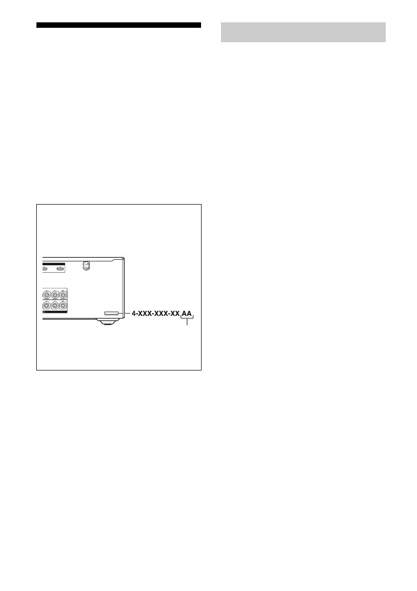
About area codes
The area code of the receiver you purchased is
shown on the lower right portion of the rear panel
(see the illustration below).
Any differences in operation, according to the area
code, are clearly indicated in the text, for example,
“Models of area code AA only”.
LR
OUT
FRONT A
LR
SURROUND
Area code
On copyrights
5
US
The Bluetooth word mark and logos are owned by
the Bluetooth SIG, Inc. and any use of such marks
by Sony Corporation is under license.
Other trademarks and trade names are those of their
respective owners.
M-crew Server” is a trademark of Sony
Corporation.
x.v.Color” and “x.v.Color” logo are trademarks of
Sony Corporation.
BRAVIA” is a trademark of Sony Corporation.
S-AIR” and its logo are trademarks of Sony
Corporation.
DLNA and DLNA CERTIFIED are trademarks
and/or service marks of the Digital Living Network
Alliance.
The receiver is compatible with the S-AIR function,
which allows transmission of sound between S-AIR
products wirelessly.
The following S-AIR products can be used with the
receiver:
Surround amplifier: You can enjoy surround
speaker sound wirelessly.
S-AIR receiver: You can enjoy receiver sound in
another room.
These S-AIR products can be purchased as an option
(the S-AIR product lineup differs depending on the
area).
Notes or instructions for the surround amplifier or
S-AIR receiver in this operating instructions refer
only to when the surround amplifier or S-AIR
receiver is used.
For details on the S-AIR function, see “S-AIR
Operations” (page 97).
About the S-AIR function
6
US
Table of Contents
Description and location of parts...................8
Getting Started
1: Installing speakers ...................................17
2: Connecting speakers ................................19
3: Connecting the TV ..................................21
4a: Connecting the audio components.........23
4b: Connecting the video components ........25
5: Connecting the antennas (aerials)............35
6: Preparing the receiver and the remote .....36
7: Displaying the GUI menu on the
TV screen................................................37
8: Selecting the front speaker system ..........38
9: Calibrating the appropriate speaker
settings automatically
(Auto Calibration) ..................................40
Guide to on-screen display operation ..........45
Playback
Enjoying sound/images from the
component connected to the receiver .....47
Enjoying sound/images from the
components connected to the
DIGITAL MEDIA PORT .......................49
Tuner Operations
Listening to FM/AM radio ..........................52
Presetting FM/AM radio stations ................54
Listening to Satellite Radio .........................55
Connecting the SIRIUS Satellite Radio ......56
Preparing to listen to the SIRIUS
Satellite Radio ........................................57
Selecting a channel of the SIRIUS
Satellite Radio ........................................58
Presetting SIRIUS Satellite Radio
channels ..................................................59
Restricting access to specific channels
(Parental Lock) .......................................60
Enjoying Surround Sound
Playing back with 2-channel sound ............ 63
Playing back with multi-channel
surround ................................................. 64
Enjoying a surround effect for
music/movie........................................... 67
Resetting sound fields to the initial
settings ................................................... 70
Amplifier Operations
Using the setting menu ............................... 70
Settings for the Auto Calibration
(Auto Calibration menu) ........................ 72
Setting for the speaker
(Speaker Settings menu) ........................ 73
Settings for the surround sound
(Surround Settings menu) ...................... 77
Settings for the EQ (EQ menu)................... 78
Settings for the audio
(Audio Settings menu) ........................... 78
Settings for the video
(Video Settings menu) ........................... 79
Settings for HDMI
(HDMI Settings menu) .......................... 81
Settings for the S-AIR
(S-AIR Settings menu)........................... 82
Operating without connecting to a TV ....... 82
“BRAVIA” Sync Features
What is “BRAVIA” Sync? .......................... 93
Preparing for the “BRAVIA” Sync ............. 94
Playing back components with one-touch
operation (One-Touch Play)................... 96
Enjoying the TV sound from the speakers
connected to the receiver
(System Audio Control)......................... 96
Turning off the receiver with the TV
(System Power Off) ............................... 97
7
US
S-AIR Operations
About S-AIR products ................................ 97
Setting up an S-AIR product ....................... 99
Enjoying the system’s sound in another
room ..................................................... 104
Changing the channel
for better sound transmission ............... 105
Stabilizing S-AIR reception ...................... 106
Enjoying the S-AIR receiver while the
S-AIR main unit is in standby mode.... 107
Other Operations
Switching between digital and analog
audio (INPUT MODE) ........................ 108
Enjoying the sound/images from other
inputs.................................................... 109
Using the Sleep Timer............................... 111
Changing the brightness of the front
panel display (DIMMER) .................... 111
Enjoying the surround effect at low
volume levels (NIGHT MODE)........... 112
Recording using the receiver..................... 112
Using a bi-amplifier connection................ 113
Using the Remote
Operating each component using the
remote .................................................. 115
Programming the remote........................... 117
Clearing all the contents of the remote’s
memory ................................................ 121
Additional Information
Glossary .................................................... 122
Precautions ................................................ 125
Troubleshooting ........................................ 126
Specifications ............................................ 133
Index.......................................................... 135
8
US
Description and location of parts
Front panel
MULTI CHANNEL DECODING
?/1
INPUT SELECTOR
MUTING
MASTER
VOLUME
SPEAKERS
PHONES
2 CH/
A.DIRECT
A.F.D. MOVIE MUSIC INPUT MODE DIMMER DISPLAY
VIDEO 2 IN
VIDEO L AUDIO R
AUTO CAL MIC
6
8
4375
9q;qaqsqdqfqgqh
12
Name Function
A ?/1 (on/standby) Press to turn the receiver on
or off (page 36, 37, 54, 70).
B Remote sensor Receives signals from
remote commander.
C White lamp Lights up when the receiver
is on.
Lights off when the
receiver is off or the
“DIMMER” is set to
“70% DOWN”.
D MULTI
CHANNEL
DECODING lamp
Lights up when multi
channel audio signals are
decoded (page 128).
E Display The current status of the
selected component or a list
of selectable items appears
here (page 10).
Name Function
F MUTING Press to turn off the sound
temporarily.
Press MUTING again to
restore the sound (page 48,
126).
G INPUT
SELECTOR +/–
Press repeatedly to select
the input source to playback
(page 48, 108, 112).
H MASTER
VOLUME
Turn to adjust the volume
level of all speakers at the
same time (page 48, 126).
I VIDEO 2 IN
jacks
Connects to a portable
audio/video component
such as a camcorder or
video game (page 32, 48).
9
US
Name Function
J AUTO CAL MIC
jack
Connects to the supplied
optimizer microphone for
the Auto Calibration
function (page 41).
K DISPLAY Press repeatedly to select
information displayed on
the display (page 88, 132).
L DIMMER Press repeatedly to adjust
the brightness of the display
(page 111).
M INPUT MODE Press to select the input
mode when the same
components are connected
to both digital and analog
jacks (page 108).
N 2CH/A.DIRECT Press to select a sound field
(page 63, 64, 67).
A.F.D.
MOVIE
MUSIC
O SPEAKERS Press to select the front
speaker system (page 38).
P PHONES jack Connects to headphones
(page 127).
10
US
About the indicators on the display
12
4 5
6
87 9
qh
qk
qj
q;
3
qa
qg
qf
qsqd
Name Function
A SW Lights up when subwoofer is
connected and the audio signal
is output from the
SUBWOOFER jack. While this
indicator lights up, the receiver
creates a subwoofer signal
based on the LFE signal in the
disc being played back or the
low frequency components of
the front channels.
B LFE Lights up when the disc being
played back contains an LFE
(Low Frequency Effect)
channel and the LFE channel
signal is actually being
reproduced.
C Input
indicators
COAX
OPT
HDMI
DMPORT
ANALOG
Light up to indicate the current
input.
Lights up when INPUT MODE
is set to “AUTO” and the source
signal is a digital signal being
input through the COAXIAL
jack (page 108).
Lights up when INPUT MODE
is set to “AUTO” and the source
signal is a digital signal being
input through the OPTICAL
jack (page 108).
The receiver recognizes a
component connected via an
HDMI IN jack.
The DIGITAL MEDIA PORT
adapter is connected and
“DMPORT” is selected.
No digital signal is being input.
When INPUT MODE is set to
“ANALOG” or when the
“Analog Direct” is being
selected, it also lights up.
Name Function
D Dolby
Digital
Surround
indicators
D
D EX
D+
TrueHD
Lights up one of the respective
indicators when the receiver is
decoding the corresponding
Dolby Digital format signals.
Dolby Digital
Dolby Digital Surround EX
Dolby Digital Plus
Dolby TrueHD
Note
When playing a Dolby Digital
format disc, be sure that you
have made digital connections
and that INPUT MODE is set
to “AUTO” (page 108).
E Neural-THX Lights up when the receiver
applies Neural-THX
processing to input signals.
F DTS(-ES)
indicators
DTS
DTS 96/24
NEO:6
DTS-ES
Light up when DTS or DTS-
ES signals are input.
Lights up when the receiver is
decoding DTS signals.
Lights up when the receiver is
decoding DTS 96 kHz/24 bit
signals.
Lights up when DTS Neo:6
Cinema/Music decoder is
activated (page 66).
Lights up when the receiver is
decoding DTS-ES signals.
Note
When playing a DTS format
disc, be sure that you have
made digital connections and
that INPUT MODE is set to
AUTO” (page 108).
11
US
Name Function
G D.RANGE Lights up when dynamic range
compression is activated.
H SP A/SP B/
SP A+B
Lights up according to the front
speaker system used (page 38).
However, these indicators do not
light up if the speaker output is
turned off or if headphones are
connected.
I SLEEP Lights up when the Sleep Timer is
activated.
J A.DIRECT Lights up when “Analog Direct”
is selected.
K Tu nin g
indicators
CAT
MEM
MONO
ST
SIRIUS
Lights up when the receiver tunes
in radio stations, or satellite radio
stations.
The category mode is selected
during the satellite radio
operation.
Lights up when a memory
function, such as Preset Memory
(page 54), etc., is activated.
Monaural broadcast
Stereo broadcast
The SiriusConnect Home tuner is
connected and “SR” is selected.
L S-AIR Lights up when the S-AIR
transmitter (not supplied) is
connected.
M Dolby
Pro Logic
indicators
PL
PL II
PL IIx
Lights up one of the respective
indicators when the receiver
applies Dolby Pro Logic
processing to 2 channel signals in
order to output the center and
surround channel signals.
Dolby Pro Logic
Dolby Pro Logic II
Dolby Pro Logic IIx
Note
These indicators do not light up
when either the center speaker and
surround speaker is not connected.
N BI-AMP Lights up when “SB Assign” is set
to “BI-AMP” (page 113).
O EQ Lights up when the equalizer is
activated.
Name Function
P DTS-HD
indicators
DTS-HD
MSTR
DTS-HD HI
RES
Lights up one of the respective
indicators when the receiver is
decoding the corresponding
DTS-HD format signals.
DTS-HD Master Audio
DTS-HD High Resolution
Audio
Q LPCM Lights up when Linear PCM
(Pulse Code Modulation)
signals are input.
R Playback
channel
indicators
L
R
C
SL
SR
S
SBL
SBR
SB
The letters (L, C, R, etc.)
indicate the channels being
played back. The boxes around
the letters vary to show how the
receiver downmixes the source
sound (based on the speaker
settings).
Front Left
Front Right
Center (monaural)
Surround Left
Surround Right
Surround (monaural or the
surround components obtained
by Pro Logic processing)
Surround Back Left
Surround Back Right
Surround Back (the surround
back components obtained by
6.1 channel decoding)
Example:
Recording format (Front/
Surround): 3/2.1
Output channel: When “SP
Pattern” is set to “3/0.1”
(page 73, 85)
Sound Field: “A.F.D. Auto”
12
US
Rear panel
68
143
576
2
LR
VIDEO
OUT
MONITOR
L
R
DIGITAL
(ASSIGNABLE)
DC5V
0.7A MAX
HDMI
ANTENNA
DMPORT
IN 4
ASSIGNABLE (INPUT ONLY)
IN 3
IN 2
IN 3
IN 1
OUT
AM
Y
P
B
/
C
B
COMPONENT VIDEO
OUT
IN
P
R
/
C
R
IN 2
IN 1
MONITOR
OUT
SA-CD/CD/CD-R
VIDEO 1
IN
TV
AUDIO
IN
VIDEO
IN
SAT
AUDIO
OUT
AUDIO
OUT
VIDEO
OUT
OPTICAL IN
AUDIO
IN
VIDEO
IN
SUBWOOFER
AUDIO
IN
VIDEO
IN
BD
LR
L
R
SPEAKERS
SAT IN BD IN
DVD IN
OPTICAL
CENTER
FRONT A
COAXIAL
ASSIGNABLE (INPUT ONLY)
SURROUND BACK/
FRONT B/
BI-AMP
TV
SIRIUS
LR
SURROUND
(for AUDIO)
EZW-T100
A S-AIR (EZW-T100)
CAUTION
Please do not remove
the slot cover until
you want to install
the wireless
transmitter.
Connects to a
wireless transmitter
(not supplied) (page
99).
B DMPORT
DMPORT
jack
Connects to a Sony
DIGITAL MEDIA
PORT adapter
(page 23).
With slot cover
slot
C ANTENNA section
FM
ANTENNA
jack
Connects to the FM
wire antenna (aerial)
supplied with this
receiver (page 35).
AM
ANTENNA
terminals
Connects to the AM
loop antenna (aerial)
supplied with this
receiver (page 35).
SIRIUS jack Connects to a
SiriusConnect Home
tuner (not supplied)
(page 56).
13
US
* You can watch the selected input image when you
connect the MONITOR OUT or HDMI OUT jack
to a TV (page 21). You can operate this receiver
using a GUI (Graphical User Interface) if you
connect HDMI OUT jack or COMPONENT
VIDEO MONITOR OUT jacks to a TV (page 37).
D DIGITAL INPUT/OUTPUT section
OPTICAL
IN jacks
Connects to a BD
player, etc. (page
21, 26, 29, 30, 31).
COAXIAL
IN jack
HDMI IN/
OUT* jacks
Connects to a DVD
player, satellite
tuner, or a Blu-ray
disc player. The
image is output to a
TV or a projector
while the sound can
be output from a TV
or/and speakers
connected to this
receiver (page 21,
26).
E SPEAKERS section
Connects to
speakers (page 19).
F AUDIO INPUT/OUTPUT section
AUDIO IN/
OUT jacks
Connects to a Super
Audio CD player,
etc. (page 21, 23,
26).
AUDIO OUT
jack
Connects to
subwoofer (page
19).
G VIDEO/AUDIO INPUT/OUTPUT
section
AUDIO IN/
OUT jacks
Connects to a VCR,
Blu-ray disc player,
etc. (page 30, 31,
32).
VIDEO IN/
OUT* jacks
White (L)
Red (R)
Black
White (L)
Red (R)
Yellow
H COMPONENT VIDEO INPUT/
OUTPUT section
Y, PB/CB,
P
R/CR IN/
OUT* jacks
Connects to a BD
player, TV, satellite
tuner, etc. (page 21,
29, 30, 31).
Green
(Y)
Blue
(P
B/CB)
Red
(P
R/CR)
14
US
You can use the supplied remote to operate the
receiver and to control the Sony audio/video
components that the remote is assigned to
operate.
You can also program the remote to control
non-Sony audio/video components. For
details, see “Programming the remote” (page
117).
RM-AAP040
Remote commander
1 2 3
4 5 6
7 8 9
-/-- 0/10
ENT/MEM
2CH/
A.DIRECT
A.F.D. MOVIE MUSIC
THEATER
SYSTEM STANDBY
RM SET UP
?/1
CLEAR
/
>10
SHIFT
TUNING – TUNING +
DISC SKIP D.TUNING
RESOLUTION
.
mM
>
Xx
MUTING
VIDEO 1 VIDEO 2 BD
SAT TV
HDMI 3HDMI 2HDMI 1
HDMI 4
SA-CD/
CD
DMPORTTUNER
TV VOL
MASTER VOL
TV CH
PRESET
<
<
MENU
AV
?/1
F1 F2
TV INPUT
TOP MENU MENU
BD/DVD
WIDE
RETURN/
EXIT
TOOLS/
OPTIONS
HOME
DISPLAY
GUI MODE
O
DVD
INPUT
MODE
SLEEP
NIGHT
MODE
TV AMP
– CATEGORY +
CATEGORY MODE
1
2
3
4
5
6
7
8
0
qs
qd
qf
qg
9
qh
qj
qk
ql
w;
wa
wd
wf
wh
ws
qa
wg
Name Function
A AV ?/1
a)
(on/standby)
Press to turn on or off the
audio/video components that
the remote is programmed to
operate.
To turn the TV on or off, press
TV (D) and then press AV
?/1.
If you press ?/1 (B) at the
same time, it will turn off the
receiver and other components
(SYSTEM STANDBY).
Note
The function of the AV ?/1
switch changes automatically
each time you press the input
buttons (E).
B ?/1
(on/standby)
Press to turn the receiver on or
set it to the standby mode.
To turn off all components,
press ?/1 and AV ?/1 (A) at
the same time (SYSTEM
STANDBY).
Saving the power in
standby mode.
When “Ctrl for HDMI” is set
to “OFF” (page 94) and
“S-AIR Stby” is set to “OFF”
(page 107).
C AMP Press to enable the receiver
operation (page 82).
D TV Press to light up the button. It
changes the remote key
function to activate the buttons
with yellow printing. It also
activate the DISPLAY (U),
TOOLS/OPTIONS (K),
HOME (L), RETURN/EXIT
O (T), (J), and V/v/
B/b (J) buttons to perform
menu operations for Sony TVs
only.
E Input buttons
(SAT
b)
)
Press one of the buttons to
select the component you want
to use. When you press any of
the input buttons, the receiver
turns on. The buttons are
factory assigned to control
Sony components (page 48).
You can program the remote to
control non-Sony components
following the steps in
“Programming the remote” on
page 117.
15
US
Name Function
Numeric
buttons
a)
(number 5
b)
)
Press SHIFT (X), then press
numeric buttons to
– preset/tune to preset stations.
– select track numbers of the
CD player, DVD player,
Blu-ray disc player or MD
deck, etc. Press 0/10 to select
track number 10.
– select channel numbers of
the VCR or satellite tuner,
etc.
Press TV (D) and then press
the numeric buttons to select
the TV channels.
ENT/MEM
a)
Press SHIFT (X), then press
ENT/MEM to
enter the value after selecting
a channel, disc or track using
the numeric buttons.
– store a station during tuner
operation.
To enter the value of Sony TV,
press TV (D) and then press
ENT/MEM.
CLEAR
a)
Press SHIFT (X), then press
CLEAR to
– clear a mistake when you
press the incorrect numeric
button.
return to continuous
playback, etc. of the satellite
tuner or DVD player.
-/--
a)
Press SHIFT (X), then press
-/-- to select the channel entry
mode, either one or two digit
of the VCR or satellite tuner.
To select the channel entry
mode of the TV, press TV (D)
and then press -/--.
>10
a)
Press SHIFT (X), then press
>10 to
– select track numbers over 10
of the CD player, DVD
player, Blu-ray disc player or
MD deck, etc.
– select channel numbers of
the Digital CATV terminal.
F 2CH/
A.DIRECT
Press to select a sound field
(page 63, 64, 67).
A.F.D.
MOVIE
MUSIC
Name Function
G SLEEP Press to activate the Sleep
Timer function and the
duration which the receiver
turns off automatically
(page 111).
H NIGHT MODE Press to activate the NIGHT
MODE function (page 112).
I GUI MODE Press to display the GUI menu
on the TV screen.
J
V/v/B/b
a)
Press V/v/B/b to select the
menu items.
Then press to enter the
selection.
K TOOLS/
OPTIONS
a)
Press to display and select
items from the option menus
for receiver, DVD player,
Blu-ray disc player or satellite
tuner.
Press TV (D) and then press
TOOLS/OPTIONS to display
the options of Sony TV.
L HOME
a)
,
MENU
a)
Press to display the menu to
operate the audio/video
components.
To display the menus of Sony
TV, press TV (D) and then
press HOME.
M ./>
a)
m/M
a)
N
a)b)
X
a)
x
a)
Press to operate the DVD
player, Blu-ray disc player,
CD player, MD deck, tape
deck, or component
connected to the DIGITAL
MEDIA PORT adapter, etc.
/
a)
Press to replay the previous
scene or fast forward the
current scene of the DVD
player or Blu-ray disc player,
etc.
TUNING +/–
a)
Press to scan a station.
CATEGORY
MODE
Press to select the category
mode for satellite tuner (page
58, 92).
CATEGORY
+/–
Press to select a category for
satellite tuner (page 59, 92).
D.TUNING Press to enter direct tuning
mode (page 53, 91).
N TV CH +
b)
/–
a)
Press TV (D) and then press
TV CH +/– to select preset
TV channels.
,
a)
<
<
continued
16
US
a)
See the table on page 116 for information on the
buttons that you can use to control each
component.
b)
The number 5/SAT, TV CH +/PRESET + and N
buttons have tactile dots. Use the tactile dots as
references when operating the receiver.
Notes
• Some functions explained in this section may not
work depending on the model.
The above explanation is intended to serve as an
example only. Therefore, depending on the
component, the above operation may not be
possible or may operate differently than described.
Name Function
PRESET
+
b)
/–
a)
Press to
– select preset stations.
– select preset channels of the
VCR, satellite tuner,
Blu-ray disc player, DVD
player, LD player, DVD/
VHS COMBO, or DVD/
HDD COMBO.
O F1
a)
, F2
a)
Press BD or DVD (E), then
press F1 or F2 to select a
component.
DVD/HDD COMBO
F1: HDD
F2: DVD disc, Blu-ray disc
DVD/VHS COMBO
F1: DVD disc, Blu-ray disc
F2: VHS
P BD/DVD TOP
MENU
a)
Press to display the menu or
on-screen guide of the DVD
player, Blu-ray disc player,
PSX or DVD/VHS COMBO
on the TV screen. Then, use
V/v/B/b (J) and (J) to
perform menu operations.
BD/DVD
MENU
a)
Press to display the menu of
the DVD player or Blu-ray
disc player on the TV screen.
Then, use V/v/B/b (J) and
(J) to perform menu
operations.
TV INPUT
a)
Press TV (D) and then press
TV INPUT to select the input
signal (TV input or video
input).
WIDE
a)
Press TV (D) and then press
WIDE repeatedly to select the
wide picture mode.
Q MUTING
a)
Press to turn off the sound
temporarily. Press the button
again to restore the sound.
To mute the sound of the TV,
press TV (D) and then press
MUTING.
R TV VOL +/–
a)
Press TV (D) and then press
TV VOL +/– to adjust the TV
volume level.
MASTER
VOL +/–
a)
Press to adjust the volume
level of all speakers at the
same time.
S DISC SKIP
a)
Press to skip disc when using
a multi-disc changer.
Name Function
T RETURN/
EXIT O
a)
Press to
return to the previous menu.
– exit the menu while the
menu or on-screen guide of
the VCD player, DVD
player, etc. is displayed on
the TV screen.
To return to the previous
menu of Sony TV, press TV
(D) and then press
RETURN/EXIT O.
U DISPLAY
a)
Press to display the current
status of or information on
components connected to the
receiver.
Note
In the GUI MODE, press the
button to display the menu on
the TV screen.
V RESOLUTION Press repeatedly to change the
resolution of signals output
from the HDMI OUT or
COMPONENT VIDEO
MONITOR OUT jack
(page 79).
W INPUT MODE Press to select the input mode
when the same components
are connected to both digital
and analog jacks (page 108).
X SHIFT Press to light up the button. It
changes the remote button
function to activate the
buttons with pink printing.
Y THEATER Press to turn the Theater mode
on and off when connecting
the receiver to products
featuring “BRAVIA” Sync.
Z RM SET UP Press to set up the remote.
17
US
Getting Started
1: Installing speakers
This receiver allows you to use a 7.1 channel
system (7 speakers and one subwoofer).
To fully enjoy theater-like multi channel
surround sound requires five speakers (two
front speakers, a center speaker, and two
surround speakers) and a subwoofer (5.1
channel).
Example of a 5.1 channel
speaker system configuration
AFront speaker (left)
BFront speaker (right)
CCenter speaker
DSurround speaker (left)
ESurround speaker (right)
HSubwoofer
You can enjoy high fidelity reproduction of
DVD or Blu-ray disc software recorded sound
in the Surround EX format if you connect one
additional surround back speaker (6.1 channel
system) or two surround back speakers (7.1
channel system).
Example of a 7.1 channel
speaker system configuration
AFront speaker (left)
BFront speaker (right)
CCenter speaker
DSurround speaker (left)
ESurround speaker (right)
FSurround back speaker (left)
GSurround back speaker (right)
HSubwoofer
Getting Started
Enjoying a 5.1/7.1 channel
system
continued
18
US
Tips
When you connect a 7.1 channel speaker system,
the angle A should be the same.
When you connect a 6.1 channel speaker system,
place the surround back speaker behind the
listening position.
Since the subwoofer does not emit highly
directional signals, you can place it wherever you
want.
19
US
Getting Started
2: Connecting speakers
Before connecting cords, be sure to disconnect the AC power cord (mains lead).
AFront speaker A (left)
BFront speaker A (right)
CCenter speaker
DSurround speaker (left)
ESurround speaker (right)
FSurround back speaker (left)
a)b)c)
GSurround back speaker (right)
a)b)c)
HSubwoofer
d)
VIDEO
OUT
MONITOR
DIGITAL
(ASSIGNABLE)
C
5V
7
A MAX
HDMI
ANTENNA
M
PORT
IN 4 IN 2
IN 3
AM
VIDEO 1
AUDIO
OUT
VIDEO
OUT
OPTICAL IN
AUDIO
IN
VIDEO
IN
AUDIO
IN
VIDEO
IN
BD
L
R
SAT IN BD IN
DVD IN
OPTICAL
COAXIAL
TV
SIRIUS
AUDIO
OUT
SUBWOOFER
LRLR
FRONT A
SURROUND BACK/
FRONT B/
BI-AMP
R
13
/32 in.
(10 mm)
CENTER
L
SURROUND
SPEAKERS
ASSIGNABLE (INPUT ONLY)
IN 1
OUT
(for AUDIO)
H
AB
B
FG
A Monaural audio cord (not supplied)
B Speaker cord (not supplied)
E
B
CD
A
continued
20
US
a)
If you connect only one surround back speaker,
connect it to the SPEAKERS SURROUND
BACK/FRONT B/BI-AMP L terminals.
b)
If you are not using surround back speaker, and
you have an additional front speaker system,
connect the additional front speaker system to the
SPEAKERS SURROUND BACK/FRONT B/
BI-AMP terminals. Set “SB Assign” to “Speaker
B” in the Speaker Settings menu (page 73).
You can select the front speaker system you want
to use with SPEAKERS on the front panel
(page 38).
c)
If you are not using surround back speakers, you
can connect the front speakers to the SPEAKERS
SURROUND BACK/FRONT B/BI-AMP
terminals using a bi-amplifier connection
(page 113).
Set “SB Assign” to “BI-AMP” in the Speaker
Settings menu (page 73).
d)
When you connect a subwoofer with an auto
standby function, turn off the function when
watching movies. If the auto standby function is
set to on, it turns to standby mode automatically
based on the level of the input signal to a
subwoofer, then sound may not be output.
Note
Before connecting the AC power cord (mains lead),
make sure that metallic wires of the speaker cords
are not touching each other between the
SPEAKERS terminals.
  • Page 1 1
  • Page 2 2
  • Page 3 3
  • Page 4 4
  • Page 5 5
  • Page 6 6
  • Page 7 7
  • Page 8 8
  • Page 9 9
  • Page 10 10
  • Page 11 11
  • Page 12 12
  • Page 13 13
  • Page 14 14
  • Page 15 15
  • Page 16 16
  • Page 17 17
  • Page 18 18
  • Page 19 19
  • Page 20 20
  • Page 21 21
  • Page 22 22
  • Page 23 23
  • Page 24 24
  • Page 25 25
  • Page 26 26
  • Page 27 27
  • Page 28 28
  • Page 29 29
  • Page 30 30
  • Page 31 31
  • Page 32 32
  • Page 33 33
  • Page 34 34
  • Page 35 35
  • Page 36 36
  • Page 37 37
  • Page 38 38
  • Page 39 39
  • Page 40 40
  • Page 41 41
  • Page 42 42
  • Page 43 43
  • Page 44 44
  • Page 45 45
  • Page 46 46
  • Page 47 47
  • Page 48 48
  • Page 49 49
  • Page 50 50
  • Page 51 51
  • Page 52 52
  • Page 53 53
  • Page 54 54
  • Page 55 55
  • Page 56 56
  • Page 57 57
  • Page 58 58
  • Page 59 59
  • Page 60 60
  • Page 61 61
  • Page 62 62
  • Page 63 63
  • Page 64 64
  • Page 65 65
  • Page 66 66
  • Page 67 67
  • Page 68 68
  • Page 69 69
  • Page 70 70
  • Page 71 71
  • Page 72 72
  • Page 73 73
  • Page 74 74
  • Page 75 75
  • Page 76 76
  • Page 77 77
  • Page 78 78
  • Page 79 79
  • Page 80 80
  • Page 81 81
  • Page 82 82
  • Page 83 83
  • Page 84 84
  • Page 85 85
  • Page 86 86
  • Page 87 87
  • Page 88 88
  • Page 89 89
  • Page 90 90
  • Page 91 91
  • Page 92 92
  • Page 93 93
  • Page 94 94
  • Page 95 95
  • Page 96 96
  • Page 97 97
  • Page 98 98
  • Page 99 99
  • Page 100 100
  • Page 101 101
  • Page 102 102
  • Page 103 103
  • Page 104 104
  • Page 105 105
  • Page 106 106
  • Page 107 107
  • Page 108 108
  • Page 109 109
  • Page 110 110
  • Page 111 111
  • Page 112 112
  • Page 113 113
  • Page 114 114
  • Page 115 115
  • Page 116 116
  • Page 117 117
  • Page 118 118
  • Page 119 119
  • Page 120 120
  • Page 121 121
  • Page 122 122
  • Page 123 123
  • Page 124 124
  • Page 125 125
  • Page 126 126
  • Page 127 127
  • Page 128 128
  • Page 129 129
  • Page 130 130
  • Page 131 131
  • Page 132 132
  • Page 133 133
  • Page 134 134
  • Page 135 135
  • Page 136 136

Sony STR-DN1000 User manual

Category
AV receivers
Type
User manual

Ask a question and I''ll find the answer in the document

Finding information in a document is now easier with AI