Page is loading ...


TM 11-6625-2941-14&P
TECHNICAL MANUAL
OPERATOR’S, ORGANIZATIONAL, DIRECT SUPPORT,
AND GENERAL SUPPORT MAINTENANCE MANUAL
INCLUDING REPAIR PARTS AND SPECIAL TOOLS LIST
FOR
COUNTER, ELECTRONIC, DIGITAL READOUT
AN/USM-459
(HEWLETT-PACKARD MODEL 5328A/E42)
(NSN 6625-01-061-8928)
HEADQUARTERS, DEPARTMENT OF THE ARMY
MARCH 1979


This manual contains copyright material reproduced by permission of the
Hewlett-Packard Company.
TM 11-6625-2941-14 + P
Technical Manual
HEADQUARTERS,
DEPARTMENT OF THE ARMY
No. 11-6625-2941-14 + P
Washington, DC 28 March 1979
OPERATOR’S, ORGANIZATIONAL, DIRECT SUPPORT, AND
GENERAL SUPPORT MAINTENANCE MANUAL INCLUDING
REPAIR PARTS AND SPECIAL TOOLS LIST
FOR
COUNTER, ELECTRONIC, DIGITAL READOUT
AN/USM-459
(HEWLETT-PACKARD MODEL 5328A/E42)
(NSN 6625-01-061-8928)
REPORTING OF ERRORS
You can improve this manual by recommending improvements using
DA Form 2028-2
located in the back of the manual.
simply
tear out the self-addressed form, fill it out as shown on the
sample, fold it where shown, and drop it in the mail.
If there are no blank DA Forms 2028-2
in the back of
your manual, use the standard DA Form 2028 (Recommended Changes to
Publications and Blank Forms) and forward to the Commander, US
Army Communications and Electronics Materiel Readiness Command,
ATTN:
DRSEL-ME-MQ, Fort Monmouth, New Jersey 07703.
In either case a reply will be furnished direct to you.
This manual is an authentication of the manufacturer
s
commercial literature
which, through usage, has been found to cover the data required to operate
and maintain this equipment.
The manual was not prepared in accordance with
military specifications; therefore, the format has not been structured to
consider categories of maintenance.
TABLE OF CONTENTS
Section
Page
0
INTRODUCTION
0-1 Scope . . . . . . . . . . . . . . . . . . . . . . . . . . . . . . . . . . . . . . . . . . . . . . . 0-1
0-2 Indexes of Publications . . . . . . . . . . . . . . . . . . . . . . . . . . . . . . . 0-1
0-3 Forms and Records . . . . . . . . . . . . . . . . . . . . . . . . . . . . . . . . . . . . . 0-1
0-4 Reporting Equipment Improvement Recommendations (EIR) . . 0-1
0-5 Administrative Storage . . . . . . . . . . . . . . . . . . . . . . . . . . . . . . . . 0-1
0-6 Destruction of Army Electronics Material . . . . . . . . . . . . . . . . . . . . . . . 0-1
i/ii (blank)


Model 5328A
Table of Contents
TABLE OF CONTENTS
Section
I
GENERAL INFORMATION
. . . . . . . . . . . . . . . . . . . . . . . . . . . . . . . . . . . . . . . .
1-1.
Scope of Manual . .
. . . . . . . . . . . . . . . . . . . . . . . . . . . . . . . . . . . . . . . .
1-4.
Description
. . . . . . . . . . . . . . . . . . . . . . . . . . . . . . . . . . . . . . . . . . . . . . .
1-6.
Instrument Identification
. . . . . . . . . . . . . . . . . . . . . . . . . . . . . . . . . . .
1-8.
Applications
. . . . . . . . . . . . . . . . . . . . . . . . . . . . . . . . . . . . . . . . . . . . . .
1-16. Equipment Supplied and Accessories Available
. . . . . . . . . . . . . .
1-18. Specifications
. . . . . . . . . . . . . . . . . . . . . . . . . . . . . . . . . . . . . . . . . . . . .
II INSTALLATION
. . . . . . . . . . . . . . . . . . . . . . . . . . . . . . . . . . . . . . . . . . . . . . . . . .
2-1.
Introduction
. . . . . . . . . . . . . . . . . . . . . . . . . . . . . . . . . . . . . . . . . .
2-3.
Unpacking and Inspection
. . . . . . . . . . . . . . . . . . . . . . . . . . . . . . . . .
2-5.
Preparation for Use
. . . . . . . . . . . . . . . . . . . . . . . . . . . . . . . . . . . . . . . .
2-6.
Power Requirements
. . . . . . . . . . . . . . . . . . . . . . . . . . . . . . . . . . . .
2-8.
Fuse Replacement and Installation
. . . . . . . . . . . . . . . . . . . . . . . .
2-10.
Power Cables . .
. . . . . . . . . . . . . . . . . . . . . . . . . . . . . . . . . . . . . . . . .
2-13.
Operating Environment
. . . . . . . . . . . . . . . . . . . . . . . . . . . . . . . . . .
2-15.
Bench Operation
. . . . . . . . . . . . . . . . . . . . . . . . . . . . . . . . . . . . . . . .
2-17.
Rack Mounting
. . . . . . . . . . . . . . . . . . . . . . . . . . . . . . . . . . . . . . . . .
2-19. Packaging for Shipment
. . . . . . . . . . . . . . . . . . . . . . . . . . . . . . . . . . . .
2-20.
Original Packaging
. . . . . . . . . . . . . . . . . . . . . . . . . . . . . . . . . . . . . .
2-24.
Other Packaging Methods
. . . . . . . . . . . . . . . . . . . . . . . . . . . . . . .
2-26. Storage . . . . . . . . . . . . . . . . . . . . . . . . . . . . . . . . . . . . . . . . . . . . . .
Ill
OPERATION (OPERATORS INSTRUCTIONS)
. . . . . . . . . . . . . . . . . . . . . .
3-1.
Introduction
. . . . . . . . . . . . . . . . . . . . . . . . . . . . . . . . . . . . . . . . . . . . .
3-3.
Frequency Measurements
. . . . . . . . . . . . . . . . . . . . . . . . . . . . . . . . . .
3-9.
Period Measurements
. . . . . . . . . . . . . . . . . . . . . . . . . . . . . . . . . . . . .
3-13. Time Interval Measurements
. . . . . . . . . . . . . . . . . . . . . . . . . . . . . . .
3-20. Ratio Measurements
. . . . . . . . . . . . . . . . . . . . . . . . . . . . . . . . . . . .
3-23. Operating Controls
. . . . . . . . . . . . . . . . . . . . . . . . . . . . . . . . . . . . . . . .
3-26. Function of Controls, Indicators, Inputs, and Outputs
. . . . . . . .
3-27.
Display
. . . . . . . . . . . . . . . . . . . . . . . . . . . . . . . . . . . . . . . . . . . . . . . . .
3-29.
Power (Line)
. . . . . . . . . . . . . . . . . . . . . . . . . . . . . . . . . . . . . . . . . . . .
3-31.
Reset
. . . . . . . . . . . . . . . . . . . . . . . . . . . . . . . . . . . . . . . . . . . . . . . . . . .
3-33.
Sample Rate Control
. . . . . . . . . . . . . . . . . . . . . . . . . . . . . . . . . . . .
3-35.
Arming
. . . . . . . . . . . . . . . . . . . . . . . . . . . . . . . . . . . . . . . . . . . . . . . . .
3-37.
Frequency Resoluton, N Switch
. . . . . . . . . . . . . . . . . . . . . . . .
3-41.
Input Channel Section
. . . . . . . . . . . . . . . . . . . . . . . . . . . . . . . . . .
3-44.
A and B Channel Signal Conditioning
. . . . . . . . . . . . . . . . . . .
3-49.
Channel C Input
. . . . . . . . . . . . . . . . . . . . . . . . . . . . . . . . . . . . . . . .
3-51.
“C’’ Channel Overload Indicator . . . . . . . . . . . . . . . . . . . . . . . .
3-53.
Hysteresis Band of Trigger Levels
. . . . . . . . . . . . . . . . . . . . . . . . .
3-57.
External Frequency Standard Input. . . . . . . . . . . . . . . . . . . . . . . .
3-59.
Marker Outputs
. . . . . . . . . . . . . . . . . . . . . . . . . . . . . . . . . . . . . . . . .
3-61.
Gate/Marker Out . .
. . . . . . . . . . . . . . . . . . . . . . . . . . . . . . . . . . . . .
3-63.
1 MHz and 10 MHz Frequency Standard Outputs
. . . . . . . . . .
3-65.
Trigger Lights
. . . . . . . .
. . . . . . . . . . . . . . . . . . . . . . . . . . . . . . . . . . .
3-68. Programming Operation
. . . . . . . . . . . . . . . . . . . . . . . . . . . . . . . . . . .
3-71. Setting Add dress Switches
. . . . . . . . . . . . . . . . . . . . . . . . . . . . . . . . . .
3-75. Measurement Output Format
. . . . . . . . . . . . . . . . . . . . . . . . . . . . . .
3-77. Bus Commands
. . . . . . . . . . . . . . . . . . . . . . . . . . . . . . . . . . . . . . . . . . .
3-79. Programming Examples
. . . . . . . . . . . . . . . . . . . . . . . . . . . . . . . . . . . .
Page
1-1
1-1
1-1
1-1
1-2
1-2
1-2
2-1
2-1
2-1
2-1
2-1
2-1
2-1
2-2
2-2
2-2
2-2
2-2
2-3
2-3
3-1
3-1
3-1
3-2
3-3
3-4
3-4
3-8
3-8
3-8
3-8
3-8
3-8
3-9
3-10
3-10
3-12
3-12
3-12
3-12
3-13
3-13
3-13
3-13
3-13
3-13
3-16
3-16
3-18
iii

Model 5328A
Table of Contents
TABLE OF CONTENTS (Continued)
Section
Page
IV
THEORY OF OPERATION . . . . . . . . . . . . . . . . . . . . . . . . . . . . . . . . . . . . . . . 4-1
4-1.
Introduction . . . . . . . . . . . . . . . . . . . . . . . . . . . . . . . . . . . . . . . . . . . . .
4-1
4-3.
Overall Description . . . . . . . . . . . . . . . . . . . . . . . . . . . . . . . . . . . . . . . 4-1
4-5.
Basic Counter Operation . . . . . . . . . . . . . . . . . . . . . . . . . . . . . . . . . 4-1
4-7.
Frequency . . . . . . . . . . . . . . . . . . . . . . . . . . . . . . . . . . . . . . . . . . . . . 4-1
4-15.
Period . . . . . . . . . . . . . . . . . . . . . . . . . . . . . . . . . . . . . . . . . . . . . . . . .
4-2
4-18.
Ratio . . . . . . . . . . . . . . . . . . . . . . . . . . . . . . . . . . . . . . . . . . . . . . . . . . 4-3
4-20.
Time Interval . . . . . . . . . . . . . . . . . . . . . . . . . . . . . . . . . . . . . . . . . . 4-3
4-22.
Time interval, Resolution, and Averaging Techniques . . . . . . .
4-3
4-24.
Resolution . . . . . . . . . . . . . . . . . . . . . . . . . . . . . . . . . . . . . . . . . . . . . 4-4
4-27.
Time Interval Averaging . . . . . . . . . . . . . . . . . . . . . . . . . . . . . . . . 4-4
4-34.
Sources of Measurement Error . . . . . . . . . . . . . . . . . . . . . . . . . . . . 4-5
4-36.
±1 Count Ambiguity . . . . . .
. . . . . . . . . . . . . . . . . . . . . . . . . . . . . .
4-5
4-41.
Time Base Error . . . . . . . . . . . . . . . . . . . . . . . . . . . . . . . . . . . . . . . . 4-6
4-43.
Trigger Error
. . . . . . . . . . . . . . . . . . . . . . . . . . . . . . . . . . . . . . . . . . .
4-6
4-48.
5328A Principles of Operation
. . . . . . . . . . . . . . . . . . . . . . . . . . . . .
4-7
4-52.
Main Counter Section
. . . . . . . . . . . . . . . . . . . . . . . . . . . . . . . . . .
4-7
4-57.
Input Section
. . . . . . . . . . . . . . . . . . . . . . . . . . . . . . . . . . . . . . . . .
4-9
4-60.
Hewlett-Packard Interface Bus (HP-lB) Section . . . . . . . . . . . . 4-9
4-62.
Al Motherboard . . . . . . . . . . . . . . . . . . . . . . . . . . . . . . . . . . . . . . . . . 4-9
4-64.
Display Control
. . . . . . . . . . . . . . . . . . . . . . . . . . . . .
. . . . . . . . . . .
4-10
4-67.
State Control . . . . . . . . . . . . . . . . . . . . . . . . . . . . . . . . . . . . . . . . . .
4-10
4-69.
A3 Oscillator Support . . . .
. . . . . . . . . . . . . . . . . . . . . . . . . . . . . . . . .
4-10
4-17.
A3 Oscillator Support . . . . . . . . . . . . . . . . . . . . . . . . . . . . . . . . . . .
4-10
4-73.
A3A1 Oscillator (HP 10544A) . . . . . . . . . . . . . . . . . . . . . . . . . . . .
4-10
4-75.
Decade Counting Assembly (DCA) . . . . . . . . . . . . . . . . . . . . . . . . .
4-10
4-79.
Time Base . . . . . . . . . . . . . . . . . . . . . . . . . . . . . . . . . . . . . . . . . . . . . . .
4-11
4-83.
A2 Power Supply
. . . . . . . . . . . . . . . . . . . . . . . . . . . . . . . . . . . . . . . . .
4-11
4-85.
+5V Supply
. . . . . . . . . . . . . . . . . . . . . . . . . . . . . . . . . . . . . . . . . . . .
4-11
4-89.
A4 Function Selector . . . . . . . . . . . . . . . . . . . . . . . . . . . . . . . . . . . . .
4-12
4-91.
High Speed Multiplexer, Main Gate, and 1st Decade . . . . . .
4-12
4-94.
Arming Multiplexer and Arming FF
. . . . . . . . . . . . . . . . . . . .
4-12
4-96.
Time Base Multiplexer and Main Gate FF . . . . . . . . . . . . . . . . .
4-13
4-99.
An Example of Operation
. . . . . . . . . . . . . . . . . . . . . . . . . . . . . . .
4-13
4-103. A16 Display Assembly . . . . . . . . . . . . . . . . . . . . . . . . . . . . . . . . . .
4-13
4-107. Remote Controllable (Programmable) Input Block
Diagram Description . . . . . .
. . . . . . . . . . . . . . . . . . . . . . . . . .
4-14
4-115. Remote Controllable (Programmable) Input
Schematic Theory . . . . . . . . . . . . . . . . . . . . . . . . . . . . . . . . . . . .
4-16
4-117.
A19 Switch Control Board . . . .
. . . . . . . . . . . . . . . . . . . . . . . . .
4-16
4-122.
A12 Amplifier Board
. . . . . . . . . . . . . . . . . . . . . . . . . . . . . . . . . . . .
4-16
4-127.
A10 Synchronizer Board . . . .
. . . . . . . . . . . . . . . . . . . . . . . . . . . .
4-17
4-147.
A11 DAC Board . . . . . . . . . . . . .
. . . . . . . . . . . . . . . . . . . . . . . . . . . 4-19
4-156.
A8 Channel C lnput
. . . . . . . . . . . . . . . . . . . . . . . . . . . . . . . . . . . .
4-20
4-162. HP interface Bus Theory
. . . . . . . . . . . . . . . . . . . . . . . . . . . . . . . . . .
4-20
4-173. HP-lB A15 Interface Operation
. . . . . . . . . . . . . . . . . . . . . . . . . . . .
4-21
4-178.
Overall Operation . . . . . . . . . . . . . . . . . . . . . . . . . . . . . . . . . . . . . .
4-22
4-181.
Bus Command Mode . . . . . . . . . . . . . . . . . . . . . . . . . . . . . . . . . . .
4-22
4-183.
Listen Mode . . . . . . . . . . . . . . . .
. . . . . . . . . . . . . . . . . . . . . . . . . . . 4-22
4-185.
Talk Mode . . . . . . . . . . . . . . . . .
. . . . . . . . . . . . . . . . . . . . . . . . . . . . 4-22
4-187.
A15 Circuit Operation
. . . . . . . . . . . . . . . . . . . . . . . . . . . . . . . . . . 4-22

Model 5328A
Table of Contents
TABLE OF CONTENTS (Continued)
Section
Page
V
MAINTENANCE
. . . . . . . . . . . . . . . . . . . . . . . . . . . . . . . . . . . . . . . . . . . . . . . . .
5-1.
Introduction . . .
. . . . . . . . . . . . . . . . . . . . . . . . . . . . . . . . . . . . . . . . .
5-3.
Assembly Designations . . . . . . . . . .
. . . . . . . . . . . . . . . . . . . . . . . .
5-5.
Test Equipment . . . . . . . . . . . . . . . . . . . . . . . . . . . . . . . . . . . . . . . . . . .
5-7.
Assembly Connection Identification
. . . . . . . . . . . . . . . . . . . . . . . .
5-9.
Preventive Maintenance . . . . . . . . . . . . . . . . . . . . . . . . . . . . . . . . . . .
5-11.
Inspection . . .
. . . . . . . . . . . . . . . . . . . . . . . . . . . . . . . . . . . . . . . . . . .
5-13.
Cleaning . . . . . . . . . . . . . . . . . . . . . . . . . . . . . . . . . . . . . . . . . . . . . . .
5-15.
Performance Test . . . . . . . . . . . . . . . . . . . . . . . . . . . . . . . . . . . . . . . .
5-17. Repair . . . . . . . .
. . . . . . . . . . . . . . . . . . . . . . . . . . . . . . . . . . . . . . . . . .
5-18.
Printed Circuit Component Replacement . . . . . . . . . . . . . . . . . .
5-20.
Replacing Integrated Circuits
. . . . . . . . . . . . . . . . . . . . . . . . . . . . .
5-22. Adjustments . . . . . . . . . . . . .
. . . . . . . . . . . . . . . . . . . . . . . . . . . . . . . .
5-25.
Sensitivity Adjustments
. . . . . . . . . . . . . . . . . . . . . . . . . . . . . . . . . .
5-26.
Adjustment of A3 Oscillator Support . . . . . . . . . . . . . . . . . . . . . .
5-27. Troubleshooting . . . . . . . . . . .
. . . . . . . . . . . . . . . . . . . . . . . . . . . . . .
5-29. Troubleshooting Aids . .
. . . . . . . . . . . . . . . . . . . . . . . . . . . . . . . . . . . .
5-31.
Extender Board (05328-62016) . . . . . . . . . . . . . . . . . . . . . . . . . . . . .
5-33.
lC Troubleshooting . . . .
. . . . . . . . . . . . . . . . . . . . . . . . . . . . . . . .
5-35.
Function Signals . . . . . . .
. . . . . . . . . . . . . . . . . . . . . . . . . . . . . . . .
5-43. Troubleshooting Input Channels
. . . . . . . . . . . . . . . . . . . . . . . . . . . .
5-45.
Local Mode Troubleshooting
. . . . . . . . . . . . . . . . . . . . . . . . . . . .
5-54. Removal and Replacement Instructions
. . . . . . . . . . . . . . . . . . . . . .
5-56.
Instrument Cover Removal . . . . . . . . . . . . . . . . . . . . . . . . . . . . . . .
5-58.
Time Interval Module (Assemblies A10 and A19)
Removal Replacement . . . . . . . . . . . . . . . . . . . . . . . . . . . . . . .
5-60.
A16 Display Assembly Removal and Replacement . . . . . . . . . .
VI
REPLACEABLE PARTS . . . . . . . . . . . . . . . . . . . . . . . . . . . . . . . . . . . . . . . . . . . .
6-1.
Introduction . . . . . . . . . . . . . . . . . . . . . . . . . . . . . . . . . . . . . . . . . . . . . .
6-3.
Ordering Information . . . . . . . . . . . . . . . . . . . . . . . . . . . . . . . . . . . . .
6-5.
HP Part Number Organization . . . . . . . . . . . . . . . . . . . . . . . . . . .
6-7.
Component Parts and Materials . . . . . . . . . . . . . . . . . . . . . . . . . .
6-10.
General Usage Parts
. . . . . . . . . . . . . . . . . . . . . . . . . . . . . . . . . . . . .
6-12.
Specific Instrument Parts
. . . . . . . . . . . . . . . . . . . . . . . . . . . . . . . . .
6-14. Factory Selected Parts . . . . . . . . . . . . . . . . . . . . . . . . . . . . . . . . . . . . . .
6-16. Part Number to NSN Cross Reference Index . . . . . . . . . . . . . . . . .
Vll
MANUAL CHANGES
. . . . . . . . . . . . . . . . . . . . . . . . . . . . . . . . . . . . . . . . . . . .
7-1.
Introduction . . . . . . . . . . . . . . . . . . . . . . . . . . . . . . . . . . . . . . . . . . . . . .
7-3.
Manual Changes Sheet . . . . . . . . . . . . . . . . . . . . . . . . . . . . . . . . . . . .
Vlll
SCHEMATIC DIAGRAMS
. . . . . . . . . . . . . . . . . . . . . . . . . . . . . . . . . . . . . . . . .
8-1.
Introduction . . . . . . . . . . . . . . . . . . . . . . . . . . . . . . . . . . . . . . . . . . . . . .
8-3.
Schematic Diagrams SymboIs and Reference Designators . . . . .
8-5.
Reference Designators
. . . . . . . . . . . . . . . . . . . . . . . . . . . . . . . . . . .
8-7.
Signal Mnemonics
. . . . . . . . . . . . . . . . . . . . . . . . . . . . . . . . . . . . . . . . .
8-9.
Identification Markings o Printed-Circuit Boards
. . . . . . . . . . . . .
8-14. Assembly Locations and Component Locators
. . . . . . . . . . . . . . .
8-16. Factor Selected Components
. . . . . . . . . . . . . . . . . . . . . . . . . . . . . . .
APPENDIX A. REFERENCES
. . . . . . . . . . . . . . . . . . . . . . . . . . . . . . . ..
B. COMPONENTS OF END ITEM LIST . . . . . . . . . . . . . . . . . . . .
C.
ADDITIONAL AUTHORIZATION LIST (not applicable)
D.
MAINTENANCE ALLOCATION
. . . . . . . . . . . . . . . . . . . .
5-1
5-1
5-1
5-1
5-1
5-2
5-3
5-3
5-3
5-3
5-3
5-3
5-19
5-19
5-24
5-24
5-24
5-24
5-26
5-26
5-41
5-41
5-45
5-45
5-45
5-45
6-1
6-1
6-1
6-3
6-3
6-4
6-4
6-4
6-4
7-1
7-1
7-1
8-1
8-1
8-1
8-1
8-1
8-1
8-2
8-2
A-1
B-1
D-1
E.
EXPENDABLE SUPPLIES AND MATERIALS LIST (not applicable)
v

Model 5328A
List of Tables
LIST OF TABLES
Table
Page
1-1.
1-2.
1-3.
3-1.
3-2.
3-3.
3-4.
3-5.
3-6.
4-1.
5-1.
5-2.
5-3.
5-4.
5-5.
5-6.
5-7.
5-8.
5-9.
5-1o.
5-11.
5-12.
5-13.
5-14.
5-15.
5-16.
6-1.
6-2.
6-3.
Figure
1-1.
3-1.
3-2.
3-3.
3-4.
3-5.
3-6.
3-7.
3-8.
3-9.
3-10.
3-11.
3-13.
Equipment Supplied . . . . . . . . . . . . . . . . . . . . . . . . . . . . . . . . . . . . . . . . . . . . . . 1-2
Accessories Available . . . . . . . . . . . . . . . . . . . . . . . . . . . . . . . . . . . . . . . . . . . . .
1-2
5328A Counter Specifications
. . . . . . . . . . . . . . . . . . . . . . . . . . . . . . . . . . . . . .
1-3
Arming Status . .
. . . . . . . . . . . . . . . . . . . . . . . . . . . . . . . . . . . . . . . . . . . . . . . . .
3-9
Frequency Resolution, N Switch Settings and Gate Times
. . . . . . . . . . . . 3-9
Functions and Resolution Switch Settings
. . . . . . . . . . . . . . . . . . . . . . . . . . .
3-9
Addressing . .
. . . . . . . . . . . . . . . . . . . . . . . . . . . . . . . . . . . . . . . . . . . . . . . . . . .
3-14
Program Code Set
. . . . . . . . . . . . . . . . . . . . . . . . . . . . . . . . . . . . . . . . . . . . . . .
3-15
American Standard Code for Information interchange (ASCII) . . . . . . .
3-17
5328A input Circuit Program Code Set . . . . . . . . . . . . . . . . . . . . . . . . . . . .
4-15
5328A Assembly identification . . . . . . . . . . . . . . . . . . . . . . . . . . . . . . . . . . . . .
5-1
Recommended Test Equipment . .
. . . . . . . . . . . . . . . . . . . . . . . . . . . . . . . .
5-2
Preventive Maintenance . . . . . . . . . . . . . . . . . . . . . . . . . . . . . . . . . . . . . . . . . . . 5-2
Performance Test
. . . . . . . . . . . . . . . . . . . . . . . . . . . . . . . . . . . . . . . . . . . . . . . . .
5-4
lC Troubleshooting, A1 Motherboard . . . . . . . . . . . . . . . . . . . . . . . . . . . . .
5-27
5328A Functional Signals
. . . . . . . . . . . . . . . . . . . . . . . . . . . . . . . . . . . . . . . . .
5-30
Program Listing . . . . . . . . . . . . . . . . . . . . . . . . . . . . . . . . . . . . . . . . . . . . . . .
5-33
Program Description . . . . . .
. . . . . . . . . . . . . . . . . . . . . . . . . . . . . . . . . . . . . . .
5-36
5328A A15 Qualifiers and Signal Mnemonics
. . . . . . . . . . . . . . . . . . . . . . .
5-39
A12 Relay Operation . . . .
. . . . . . . . . . . . . . . . . . . . . . . . . . . . . . . . . . . . . . . . .
5-41
Relay Control Logic
. . . . . . . . . . . . . . . . . . . . . . . . . . . . . . . . . . . . . . . . . . . . . .
5-41
Program interface Operation
. . . . . . . . . . . . . . . . . . . . . . . . . . . . . . . . . . . . .
5-43
ROM (A10U7) Input/Output Mode
. . . . . . . . . . . . . . . . . . . . . . . . . . . . . . .
5-43
A11 DAC Logic Levels
. . . . . . . . . . . . . . . . . . . . . . . . . . . . . . . . . . . . . . . . . .
5-44
A11 DAC Signals
. . . . . . . . . . . . . . . . . . . . . . . . . . . . . . . . . . . . . . . . . . . . . . . .
5-44
A11 DAC Troubleshooting . . . . . . . . . . . . . . . . . . . . . . . . . . . . . . . . . . . . . . . . 5-44
Replaceable Parts
. . . . . . . . . . . . . . . . . . . . . . . . . . . . . . . . . . . . . . . . . . . . . . .
6-5
Manufacturers Code List . . . .
. . . . . . . . . . . . . . . . . . . . . . . . . . . . . . . . . . . . .
6-24
Part Number-NSN Cross Reference Index . . . . . . . . . . . . . .
6-25
LIST OF FIGURES
Page
Model 5328A 500 MHz Universal Frequency Counter . . . . . . . . . . . . . . . 1-0
Measuring Linearity . . . . . . . . . . . . . . . . . . . . . . . . . . . . . . . . . . . . . . . . . . . . . . . 3-2
Tone Burst Measurements . . . . .
. . . . . . . . . . . . . . . . . . . . . . . . . . . . . . . . . . . .
3-2
Deadtime
. . . . . . . . . . . . . . . . . . . . . . . . . . . . . . . . . . . . . . . . . . . . . . . . . . . . . . . .
Multiple STOP Pulses
. . . . . . . . . . . . . . . . . . . . . . . . . . . . . . . . . . . . . . . . . .
3-3
Monitoring Marker Outputs . . . . . . . . . . . . . . . . . . . . . . . . . . . . . . . . . . . . . . . 3-4
5328A Front Panel Operation Summary . . . . . . . . . . . .
. . . . . . . . . . . . . . . .
3-5
5328A Rear Panel Controls and Connectors
. . . . . . . . . . . . . . . . . . . . . . . . .
3-7
Programmable Input Switch Configuration for COM A
. . . . . . . . . . . . .
3-10
Slope Switch Settings
. . . . . . . . . . . . . . . . . . . . . . . . . . . . . . . . . . . . . .
3-11
Level Control Settings . . . . . . . . .
. . . . . . . . . . . . . . . . . . . . . . . . . . . . . . . . . . .
3-11
Hysteresis Band
. . . . . . . . . . . . . . . . . . . . . . . . . . . . . . . . . . . . . . . . . . . . . . .
3-12
5328A Measurement Cycle
. . . . . . . . . . . . . . . . . . . . . . . . . . . . . . . . . . . . . .
3-18

Model 5328A
List of Figures
LIST OF FIGURES
4-1.
4-2.
4-3.
4-4.
4-5.
4-6.
4-7.
4-8.
4-9.
4-10.
5-1.
5-2.
5-3.
5-4.
5-5.
5-6.
5-7.
5-8.
5-8.
5-9.
5-10.
5-10.
5-10.
5-11.
5-11.
5-12.
8-1.
8-2.
8-3.
8-4.
8-5.
8-6.
8-7.
8-7.
8-8.
8-9.
8-10.
8-11.
8-12.
8-13.
8-14.
8-15.
8-16.
8-17.
8-18.
8-19.
8-20.
8-21.
8-22.
8-23.
8-24.
8-25.
Basic Elements of the Frequency Counter
. . . . . . . . . . . . . . . . . . . . . . . . . . .
Measuring Period . .
. . . . . . . . . . . . . . . . . . . . . . . . . . . . . . . . . . . . . . . . . . . . . . .
Basic Elements of a Time interval Counter . . . . . . . . . . . . . . . . . . . . . . . . . .
Clock Pulses
. . . . . . . . . . . . . . . . . . . . . . . . . . . . . . . . . . . . . . . . . . . . . . . . . . . . .
Synchronizer Operation with Time Interval Averaging
. . . . . . . . . . . . . . .
±1 Count Ambiguity
. . . . . . . . . . . . . . . . . . . . . . . . . . . . . . . . . . . . . . . . . . . . . .
Trigger Error
. . . . . . . . . . . . . . . . . . . . . . . . . . . . . . . . . . . . . . . . . . . . . . . . . . . . .
Block Diagram . . . . . . . . . . . . . . . . . . . . . . . . . . . . . . . . . . . . . . . . . . . . . . . . . . .
Remote Controllable (Programmable) Input Block Diagram
. . . . . . . . .
ASM Oscillator Timing Diagram . .
. . . . . . . . . . . . . . . . . . . . . . . . . . . . . . . . .
10 MHz Oscillator Frequency Check
. . . . . . . . . . . . . . . . . . . . . . . . . . . . . .
DAC Adjustment Equipment Connectors
. . . . . . . . . . . . . . . . . . . . . . . . . .
DAC Adjustment Oscilloscope Readout and Adjustment Locations . .
Hookup for A3 Oscillator Support Adjustment
. . . . . . . . . . . . . . . . . . . . .
A3 Jitter Adjustment . . . .
. . . . . . . . . . . . . . . . . . . . . . . . . . . . . . . . . . . . . . . . .
System Configuration
. . . . . . . . . . . . . . . . . . . . . . . . . . . . . . . . . . . . . . . . . . . .
Sample Printout
. . . . . . . . . . . . . . . . . . . . . . . . . . . . . . . . . . . . . . . . . . . . . . . . .
Hookup for
Hookup for Test Described in Table 5-8B and C . . . . . . . . . . . . . . . . . . . .
Triangular Pulse Observed in Steps 5 and 7, Table 5-8B
. . . . . . . . . . . . .
Assembly Flowchart (Sheet 1 of 3) . .
. . . . . . . . . . . . . . . . . . . . . . . . . . . . . . .
Assembly Flowchart (Sheet 2 of 3)
. . . . . . . . . . . . . . . . . . . . . . . . . . . . . . . . .
Assembly Flowchart (Sheet 3 of 3) . .
. . . . . . . . . . . . . . . . . . . . . . . . . . . . . . .
Local Troubleshooting Flowchart (Sheet 1 of 2) . . . . . . . . . . . . . . . . . . . . .
Local Troubleshooting Flowchart (Sheet 2 of 2) . . . . . . . . . . . . . . . . . . . . .
Address Switch Troubleshooting Flowchart
. . . . . . . . . . . . . . . . . . . . . . . .
Schematic Diagram Notes . .
. . . . . . . . . . . . . . . . . . . . . . . . . . . . . . . . . . . . . . .
5328A Front View
. . . . . . . . . . . . . . . . . . . . . . . . . . . . . . . . . . . . . . . . . . . . . . . . .
5328A Rear View
. . . . . . . . . . . . . . . . . . . . . . . . . . . . . . . . . . . . . . . . . . . . . . . . .
5328A Top View
. . . . . . . . . . . . . . . . . . . . . . . . . . . . . . . . . . . . . . . . . . . . . . . . . .
5328A Bottom View
. . . . . . . . . . . . . . . . . . . . . . . . . . . . . . . . . . . . . . . . . . . . . . .
A1 Motherboard . . . . . . . . . . . . . . . . . . . . . . . . . . . . . . . . . . . . . . . . . . . . . . . .
A1 Motherboard Schematic and Components (Sheet 1 of 2) . . . . . . . . .
A1 Motherboard Schematic and Components (Sheet 2 of 2)
. . . . . . . . .
A2 Power Supply Block Diagram . .
. . . . . . . . . . . . . . . . . . . . . . . . . . . . . . . .
A2 Power Supply Schematic and Components . . . . . . . . . . . . . . . . . . . . . .
4-1
4-2
4-3
4-3
4-5
4-5
4-7
4-8
4-14
4-24
5-19
5-22
5-23
5-24
5-25
5-31
5-32
5-36
5-38
5-47
5-49
5-51
5-52
5-53
5-54
8-3
8-7
8-7
8-8
8-9
8-11
8-17
8-19
8-18
8-19
A3/A3A1 Oscillator Support Schematic and Components . . . . . . . . . . . . . 8-21
A4 Function Selector Block Diagram
. . . . . . . . . . . . . . . . . . . . . . . . . . . . . .
8-23
A4 Function Selector Schematic and Components . . . . . . . . . . . . . . . . . .
8-25
A8 Channel “C” Block Diagram . . . . . . .
. . . . . . . . . . . . . . . . . . . . . . . . . . . .
8-26
A8 Channel “C” Schematic and Components
. . . . . . . . . . . . . . . . . . . . . .
8-27
A10 Synchronizer Block Diagram
. . . . . . . . . . . . . . . . . . . . . . . . . . . . . . . . . .
8-28
A10 Synchronizer Schematic and Components
. . . . . . . . . . . . . . . . . . . . .
8-29
A11 Digital-to-Analog Converter Block Diagram . . . . . . . . . . . . . . . . . . . .
8-30
A11 Digital-to-Analog Converter Schematic and Components
. . . . . . .
8-31
A12 “A-B” Channel Block Diagram
. . . . . . . . . . . . . . . . . . . . . . . . . . . . . . . .
8-32
A12 “A-B” Channel Schematic and Components . . . . . . . . . . . . . . . . . . .
8-33
A15 HP-IB Interface Block Diagram
. . . . . . . . . . . . . . . . . . . . . . . . . . . . . .
8-35
A15 HP-IB Interface Schematic and Components
. . . . . . . . . . . . . . . . . . .
8-37
A16 Display Block Diagram . . . . . . . . . . .
. . . . . . . . . . . . . . . . . . . . . . . . . . . .
8-39
A16 Display Schematic and Components
. . . . . . . . . . . . . . . . . . . . . . . . . .
8-41
A19 Switch/Attenuator Schematic and Components
. . . . . . . . . . . . . . . .
8-43
vii

Model 5328A
Safety Considerations
SAFETY CONSIDERATIONS
GENERAL
This is a Safety Class I instrument. This instrument has been designed and tested according to
IEC Publication 348, “Safety Requirements for Electronic Measuring Apparatus.”
OPERATION
BEFORE APPLYING POWER verify that the power transformer primary is matched to the
available line voltage and the correct fuse is installed (see Section II). Make sure that only
fuses with the required rated current and of the specified type (normal blow, time delay, etc.) are
used for replacement. The use of repaired fuses and the short-circuiting of fuseholders must
be avoided.
SERVICE
Although this instrument has been designed in accordance with international safety standards,
this manual contains information, cautions, and warnings which must be followed to ensure
safe operation and to retain the instrument in safe condition. Service and adjustments should
be performed only by qualified service personnel.
Any adjustment, maintenance, and repair of the opened instrument under voltage should be
avoided as much as possible and, when inevitable, should be carried out only by a skilled person
who is aware of the hazard involved.
Capacitors inside the instrument may still be charged even if the instrument has been discon-
nected from its source of supply.
Whenever it is likely that the protection has been impaired, the instrument must be made in-
operative and be secured against any unintended operation.
viii

Model 5328A
Safety Considerations
WARNING
IF THIS INSTRUMENT IS TO BE ENERGIZED VIA AN AUTOTRANS-
FORMER (FOR VOLTAGE REDUCTION] MAKE SURE THE COMMON
TERMINAL IS CONNECTED TO THE EARTHED POLE OF THE POWER
SOURCE.
WARNING
BEFORE SWITCHING ON THE INSTRUMENT, THE PROTECTIVE EARTH
TERMINALS OF THE INSTRUMENT MUST BE CONNECTED TO THE
PROTECTIVE CONDUCTOR OF THE (MAINS) POWER CORD. THE
MAINS PLUG SHALL ONLY BE INSERTED IN A SOCKET OUTLET PRO-
VIDED WITH A PROTECTIVE EARTH CONTACT. THE PROTECTIVE
ACTION MUST NOT BE NEGATED BY THE USE OF AN EXTENSION
CORD (POWER CABLE) WITHOUT A PROTECTIVE CONDUCTOR
(GROUNDING).
WARNING
THE SERVICE INFORMATION FOUND IN THIS MANUAL IS OFTEN
USED WITH POWER SUPPLIED AND PROTECTIVE COVERS REMOVED
FROM THE INSTRUMENT. ENERGY AVAILABLE AT MANY POINTS
MAY, IF CONTACTED, RESULT IN PERSONAL INJURY.
CAUTION
BEFORE SWITCHING ON THIS INSTRUMENT:
1.
2.
3.
4.
MAKE SURE THE INSTRUMENT IS SET
THE POWER SOURCE.
TO THE VOLTAGE OF
ENSURE THAT ALL DEVICES CONNECTED TO THIS INSTRU-
MENT ARE CONNECTED TO THE PROTECTIVE (EARTH) GROUND.
ENSURE THAT THE LINE POWER (MAINS) PLUG IS CONNEC-
TED TO A THREE-CONDUCTOR LINE POWER OUTLET THAT HAS
A PROTECTIVE (EARTH) GROUND. (GROUNDING ONE CON-
DUCTOR OF A TWO-CONDUCTOR OUTLET IS NOT SUFFICIENT.)
MAKE SURE THAT ONLY FUSES WITH THE REQUIRED RATED
CURRENT AND OF THE SPECIFIED TYPE (NORMAL BLOW,
TIME DELAY, ETC.) ARE USED FOR REPLACEMENT. THE USE
OF REPAIRED FUSES AND THE SHORT-CIRCUITING OF FUSE
HOLDERS MUST BE AVOIDED.
ix

TM 11-6625-2941-14&P
SECTION O
INTRODUCTION
0-1. SCOPE
This manual describes Counter, Electronic, Digital Readout AN/USM-459 and
provides instructions for operation and maintenance. Throughout this manual,
the AN/USM-459 is referred to as Hewlett-Packard Model 5328A Counter.
0-2.
INDEXES OF PUBLICATIONS
a.
DA Pam 310-4. Refer to the latest issue of DA Pam 310-4 to determine
whether there are new editions,
changes, or additional publications pertain-
ing to the equipment.
b.
DA Pam 310-7.
Refer to DA Pam 310-7 to determine whether there are
modification work orders (MWO's) pertaining to the equipment.
0-3.
FORMS AND RECORDS
a. Reports of Maintenance and Unsatisfactory Equipment. Maintenance
forms, records,
and reports which are to be used by maintenance personnel at
all maintenance levels are listed in and prescribed by TM 38-750.
b.
Report of Packaging and Handling Deficiencies. Fill out and forward
DD Form 6 (Packaging Improvement Report) as prescribed in AR 700-58/NAVSUPINST
4030.29/AFR 71-13/MCO P4030.29A and DLAR 4145.8.
c.
Discrepancy in Shipment Report (DISREP) (SF 361). Fill out and for-
ward Discrepancy in Shipment Report (DISREP) (SF 361) as prescribed in AR
55-38/NAVSUPINST 4610.33B/AFR 75-18/MCO P4610.19C and DLAR 4500.15.
0-4.
REPORTING EQUIPMENT IMPROVEMENT RECOMMENDATIONS (EIR)
EIR’s will be prepared using Standard Form 368 (Quality Deficiency Report).
Instructions for preparing EIR’s are provided in TM 38-750, The Army Mainte-
nance Management System. EIR’s should be mailed direct to Commander, US Army
Communications and Electronics Materiel Readiness Command, ATTN: DRSEL-ME-MQ,
Fort Monmouth, NJ 07703.
A reply will be furnished direct to you.
0-5.
ADMINISTRATIVE STORAGE
Administrative storage of equipment issued to and used by Army activities
shall be in accordance with paragraph 2-26.
0-6.
DESTRUCTION OF ARMY ELECTRONICS MATERIEL
Destruction of Army electronics materiel to prevent enemy use shall be in
accordance with TM 750-244-2
0-1


Model 5320A
General Information
SECTION I
GENERAL INFORMATION
1-1. SCOPE OF MANUAL
1-2. This manual provides operating and service information for the Hewlett-Packard Model
5328A/H42 500 MHz Universal Frequency Counter. (In this manual its name will be abbreviated
to “5328A” or “counter”.) A separate operators booklet contains condensed operator instructions.
1-3. This manual is divided into eight sections as listed and described below:
Section I
Section II
Section Ill
Section IV
Section V
Section VI
Section VII
Section Vlll
GENERAL INFORMATION —
Describes the counter, lists specifications, lists
items supplied, lists items required, but not supplied, describes applications,
and lists recommended maintenance and test equipment.
INSTALLATION —
Provides instructions for unpacking, inspection, prepar-
ation for use, preparation for reshipment, and preparation for storage.
OPERATION —
Provides operator instructions including frequency, measure-
ment of input signal: time period, time period average, time interval, time
interval average, and ratio between frequencies of two input signals.
THEORY OF OPERATION —
Covers a. description of the general operating
principles of the counter with reference to block and schematic diagrams
of each assembly.
MAINTENANCE — Contains maintenance and service information, including
a list of assemblies, recommended test equipment, performance checks, and
adjustment. Troubleshooting procedures and flowcharts are included in this
section.
REPLACEABLE PARTS —
Provides a complete list of replaceable parts and
parts ordering information.
MANUAL CHANGES —
Contains information on manual changes.
CIRCUIT DIAGRAMS —
Contains schematic diagrams and component lo-
cating illustrations.
1-4. DESCRIPTION
1-5. The 5328A counter can be used to measure frequency, period, period average, time
interval, time interval average, and ratio. The 5328A provides a 9-digit LED display, display
storage, and leading zero blanking. Decimal point and unit readouts are displayed automatically.
Two independent selectable input channels are provided for time interval measurements. Each
input channel has an attenuator, trigger slope selector, level control, ac or dc coupling, and an
oscilloscope marker output. Rear panel connectors provide a gate output, one- and 10-mega-
hertz output, and an input for an external frequency standard. An ARM switch on the rear panel
allows arming by the signal being measured (switch OFF) or by another input signal (switch ON).
1-6. INSTRUMENT IDENTIFICATION
1-7. Hewlett-Packard instruments have a 2-section, 10-character serial number (0000A00000),
which is located on the rear panel. The 4-digit serial prefix identifies instrument changes. If
the serial prefix of your instrument differs from that listed on the title page of this manual, there
are differences between this manual and your instrument. Instruments having higher serial
prefixes are covered with a “Manual Changes” sheet included with this manual.
1-1

Model 5328A
General Information
1-8. APPLICATIONS
1-9. Specific applications information is provided in Section III of this manual. The general
application features of the 5328A are described in the following paragraphs.
1-10. The high sensitivity, frequency range, and signal conditioning controls (see Table 7-3)
make the 5328A suited for a wide range of applications.
1-11. The rear panel controlled “ARM” feature of the 5328A is useful in applications such as
burst frequency measurements, and pulse ampltiude measurements.
1-12. The 5328A single-shot resolution of 100 ns meets the requirements for applications
such as mechanical and electromechanical device (relays) timing, time of flight measurements
(ballistics), sonar ranging, radio ranging, and navigation.
1-13. Using time interval averaging, time intervals as short as 100 picosecond, with resolution
to 10 picosecond may be measured. Applications include coaxial cable length measurements,
phase measurements, logic timing measurements, and integrated circuit propagation delay
measurement.
1-14. Full bandwidth, sensitivity, and signal conditioning of the Channel A, B, and C input
amplifiers is provided for ratio and totalizing measurements.
1-15. The 5328A HP-IB Interface is able to output measurement data and be controlled (fully
programmed) via the Hewlett-Packard Interface Bus (HP-16). The 5328A may be interfaced
to HP-IB compatible instruments, calculators, or computers by interconnecting with an HP-IB
cable.
1-16. EQUIPMENT SUPPLIED AND ACCESSORIES AVAILABLE
1-17. Table 7-7 lists equipment supplied with the 5328A and Table 7-2 lists accessories avail-
able, The Service Kits listed in Table 1-2 are described in Section III.
Table 1-1. Equipment Supplied
DESCRIPTION
HP PART NUMBER
Detachable Power Cord 231 cm (7
1
/
2
ft.) long
8120-1348
Extender Board, 18 pin
05328-62016
Table 1-2. Accessories Available
DESCRIPTION HP PART NUMBER
HP Interface Bus Interconnect Cable 10631A, 914 mm (3 ft. long)
10631B, 1828 mm (6 ft. long)
10631C, 3656 mm (12 ft. long)
10631D, 0.5 m (1
1
/
2
ft. long)
Front Handle Kit
5061-0088
Rack Flange Kit (for instruments without handles)
5061-0076
Rack and Handle Kit (installation instructions included
5061-0082
with above kits)
Service Kit:
Function Selector and ROM Kit
05328-82004
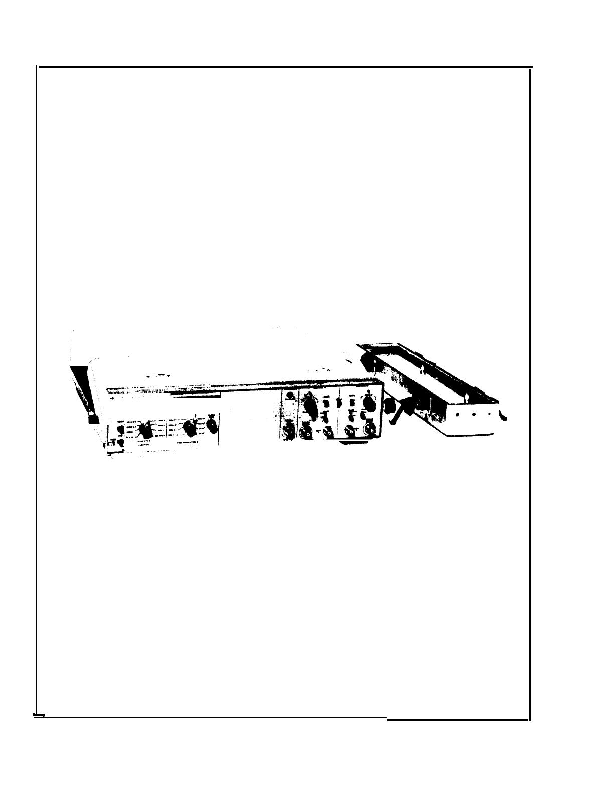
1-18. SPECIFICATIONS
1-19. Table 1-3 lists detailed specifications for the 5328AF/096.
1-2
Model 5328A
General Information
Table 1-3. 5328A Counter Specifications
GENERAL
Power Requirements:
115 or 230 volts 60 or
400 Hz ac.
Display:
Nine-digit LED.
Sample Rate:
Variable from less than 2 milli-
seconds to HOLD.
Arming:
Rear panel ARM (ON-OFF) switch.
Refer to operation for details.
Blanking:
Unwanted zeros to left of most-
significant-digit are suppressed.
Hold:
HOLDS count between samples.
Trigger Light:
Indicates input is above trigger
level.
PROGRAMMABLE OPERATION
(CHANNELS A AND B)
Includes independent selection of coupling,
trigger slope, trigger level, and attenuator for
each channel. Separate/Common A switch is
programmable. Also, an invert feature switches
Channels A and B; useful in all functions except
Ratio B/A.
Trigger level is programmable in 10 mV steps
in X1; 100 mV in X10; IV in X100.
Trigger level accuracy under remote control:
X1:
±35 mV
X10:
±350 mV +2% of trigger level
X100:
±3.5V +2% of trigger level
Input Characteristics
Sensitivity:
15 mV rms, 0—35 MHz (decoupled
20 Hz—35 MHz (ac coupled)
50 mV rms, 35 MHz—100 MHz
Minimum pulse width 5 ns, 140 mV p-p.
Coupling:
ac or dc switch selectable.
Impedance:
1
MO
II <70 pF.
Trigger Level:
Variable over ±2.5 volts times
attenuator setting with 0 volt preset position.
Trigger Slope:
Independent selection of + or
- slope.
Attenuators:
X1, X10, X100.
Dynamic Range:
25 mV to 1V rms times
attenuator setting, 0—35 MHz; 50 mV rms
times attenuator setting, 35 MHz to 100 MHz
Maximum Input:
dc coupled, X1:
250V rms, dc — SO kHz
1.25 x 10
7
V rms/freq., 50 kHz—2.5 MHz
5V rms, 2.5 MHz—100 MHz.
dc coupled, X10 and X100:
250V rms, dc 5
MHz 1.25 x 10⁹V rms/freq., 5—100 MHz
ac coupled:
200V (peak ac + dc),
0-20 Hz; same as dc coupled above 20 Hz.
Channel Input:
Separate or Common A.
Marker Outputs:
A and B channel Schmidt
trigger outputs available on front panel;
0 to 300 mV levels into
50Q;
<20 ns delay.
Frequency Measurements
Frequency A
Range:
0—100 MHz direct count.
Resolution:
1 MHz to 0.1 Hz in decade steps.
Accuracy:
±1 count ± time base error.
Display: Hz, kHz, MHz.
Period Measurements
Period A
Range:
0—10 MHz
Resolution:
10 ns to 0.1s in decade steps.
Accuracy:
±1 count ± time base error
±trigger error*
Display:
ns,
ps,
ms.
Period Average A
Range:
0—10 MHz
Resolution:
100 ns—.01 ps in decade steps.
Accuracy:
±1 count displayed ± time base
error
trigger error*
±
no. of periods averaged
Display:
Ps,
ns
Time Interval Measurements
Time Interval A to B
Range:
100 ns to 10
8
seconds
Resolution:
100 ns to 1-second in decade
steps.
Accuracy:
±1 count ± time base error
± trigger error*
Display:
ps,
ms, s.
Time Interval Average A to B
Range:
0.1 ns to 10 seconds
Resolution:
Accuracy:
Minimum Dead Time:
150 ns from one
STOP to next START
Maximum Repetition Rate:
10 MHz.
Display:
Ps,
ns.
Ratio Measurement
Ratio B/A, or C/A
Range:
A: 0—10 MHz
Range:
B: 0—100 MHz
Range:
C: 30—500 MHz
Resolution:
1 part in
~
x N
Accuracy: ±1 count of B or C ± trigger
error* of A times frequency of B or C (N>1)
For N=1, add 12 ns times frequency of
B or C.
* Trigger error is <0.3% of one period for sine waves
of 40 dB S/N or better and amplitude equal to
sensitivity of counter. For any wave shape, trigger
error is than then:
1-3

Model 5328A
General Information
Table 7-3. 5328A Counter Specifications (Continued)
CHANNEL C
Input Characteristics
Range:
30 MHz to 500 MHz direct count
Sensitivity:
15 mV rms, 30 MHz—500 MHz
Trigger level:
0 volts
Impedance:
50fl
nominal
Maximum Input:
5 volts rms
Input protection:
Input BNC fused; accessible
from front panel. protected to 200 volts peak.
overload Indicator:
flashing indicator warns
of potential overload conditions.
Resolution:
1 MHz to 0.1 Hz in decade steps
Accuracy:
±1 count ± time base error
Display: Hz, kHz, MHz
TIME BASE
Outputs:
1 MHz and 10 MHz available at rear
panel BNC in standby and operate modes
Output level:
1 volts rms into
50f)
External Input:
Operates from 1, 2.5, 5, and 10
MHz inputs at 1V rms.
Input impedance 1
K~l<30
pF
Counter automatically switches to
external mode when external input is
present.
Oscillator Aging Rate:
<5x10
10
/day after
24-hour warmup. Oscillator oven is
energized when power cable is connected
to line voltage.
1-4

Model 5328A
Installation
SECTION II
INSTALLATION
2-1. INTRODUCTION
2-2. This section provides instructions for unpacking, inspection, preparation for use, ship-
ment, and storage.
2-3. UNPACKING AND INSPECTION
2-4. If the shipping carton is damaged, inspect the counter for visible damage (scratches,
dents, etc.). If the counter is damaged, notify the carrier and the nearest Hewlett-Packard
Sales and Service Office immediately (offices are listed at the back of this manual). Keep the ship-
ping carton and packing material for the carrier’s inspection.
2-5. PREPARATION FOR USE
CAUTION
Before connecting this instrument to an ac power line, be sure that
the 115—230-volt line selector switch on the rear panel is set to the
proper position and proper line fuse is installed (see below).
2-6. Power Requirements
2-7. This instrument can be operated on single phase 115 or 230 (-10%. +5%) volts ac. Power
required is approximately 100 VA maximum. To avoid instrument damage, the rear panel line
selector switch must be set to the correct position and the correct fuse (as labeled on the rear
panel) must be installed. See Section
III for rear panel features photograph. When shipped, the
switch is set to 115-volt ac operation.
2-8. Fuse Replacement and Installation
2-9. Two fuses are supplied with the instrument. The instrument is shipped with a 2.0 ampere
fuse installed for 115- volt operation. To change the instrument for 230-volt operation discon-
nect the ac power cable, set the line selector switch and install the 1.0 ampere fuse.
2-10. Power Cables
WARNING
TO PROTECT OPERATING AND SERVICING PERSONNEL, THIS
INSTRUMENT IS EQUIPPED WITH A THREE-PIN POWER RECEP-
TACLE. THE CENTER PIN OF THE RECEPTACLE CONNECTS THE
INSTRUMENT CHASSIS AND PANELS TO EARTH GROUND WHEN
USED WITH A PROPERLY WIRED THREE CONDUCTOR OUTLET
AND POWER CABLE. IMPROPERLY GROUNDED EQUIPMENT CAN
RESULT IN HAZARDOUS POTENTIALS BETWEEN EQUIPMENTS.
2-1
/