Page is loading ...

3A2894F
EN
Setup-Operation
ExactaBlend
™
AGP
Advanced Glazing
Proportioner
For dispensing two component silicone, polysulfide, and urethane materials.
For professional use only.
Not approved for use in explosive atmospheres or hazardous locations.
See page 4 for model information, including maximum working pressure and approvals.
Important Safety Instructions
Read all warnings and instructions in this
manual. Save these instructions.
S100 Shown

Contents
2 3A2894F
Contents
Contents . . . . . . . . . . . . . . . . . . . . . . . . . . . . . . . . . . 2
Related Manuals . . . . . . . . . . . . . . . . . . . . . . . . . . . 3
Models . . . . . . . . . . . . . . . . . . . . . . . . . . . . . . . . . . . 4
Base Machines . . . . . . . . . . . . . . . . . . . . . . . . . . 4
Hose Kits . . . . . . . . . . . . . . . . . . . . . . . . . . . . . . . 5
Dispense Valves . . . . . . . . . . . . . . . . . . . . . . . . . 5
Warnings . . . . . . . . . . . . . . . . . . . . . . . . . . . . . . . . . 6
Important Isocyanate (ISO) Information . . . . . . . . 8
Isocyanate Conditions . . . . . . . . . . . . . . . . . . . . 8
Material Self-ignition . . . . . . . . . . . . . . . . . . . . . . 8
Keep Components A and B Separate . . . . . . . . . 8
Moisture Sensitivity of Isocyanates . . . . . . . . . . . 9
Changing Materials . . . . . . . . . . . . . . . . . . . . . . . 9
Component Identification . . . . . . . . . . . . . . . . . . . 10
S100 Models . . . . . . . . . . . . . . . . . . . . . . . . . . . 10
U100 Models . . . . . . . . . . . . . . . . . . . . . . . . . . . 11
P100 Models . . . . . . . . . . . . . . . . . . . . . . . . . . . 12
Display Module (DM) . . . . . . . . . . . . . . . . . . . . . 14
User Interface . . . . . . . . . . . . . . . . . . . . . . . . . . 14
Electrical Enclosure . . . . . . . . . . . . . . . . . . . . . 17
Integrated Air Controls . . . . . . . . . . . . . . . . . . . 18
Fluid Control Module (FCM) . . . . . . . . . . . . . . . 20
Installation . . . . . . . . . . . . . . . . . . . . . . . . . . . . . . . 22
Grounding . . . . . . . . . . . . . . . . . . . . . . . . . . . . . 32
Setup . . . . . . . . . . . . . . . . . . . . . . . . . . . . . . . . . . . . 33
Startup . . . . . . . . . . . . . . . . . . . . . . . . . . . . . . . . . . 42
Base Purge . . . . . . . . . . . . . . . . . . . . . . . . . . . . . . . 44
Pressure Relief Procedure . . . . . . . . . . . . . . . . . . 46
Shutdown . . . . . . . . . . . . . . . . . . . . . . . . . . . . . . . . 48
Calibration Check . . . . . . . . . . . . . . . . . . . . . . . . . 49
Maintenance . . . . . . . . . . . . . . . . . . . . . . . . . . . . . . 52
Adjust Packing Nuts . . . . . . . . . . . . . . . . . . . . . 52
Filters . . . . . . . . . . . . . . . . . . . . . . . . . . . . . . . . 52
Seals . . . . . . . . . . . . . . . . . . . . . . . . . . . . . . . . . 52
DM - Battery Replacement and Screen Cleaning 53
Software Update Procedure . . . . . . . . . . . . . . . 54
Troubleshooting . . . . . . . . . . . . . . . . . . . . . . . . . . . 55
Mechanical and Electrical . . . . . . . . . . . . . . . . . 55
Display Module . . . . . . . . . . . . . . . . . . . . . . . . . 58
Accessories and Kits . . . . . . . . . . . . . . . . . . . . . . . 60
Light Tower 24R824 . . . . . . . . . . . . . . . . . . . . . . 60
Low Level Sensors, 24R935
(S100 and P100 only) . . . . . . . . . . . . . . . . . 60
USB Kit, 24R936 . . . . . . . . . . . . . . . . . . . . . . . . 61
MD2 Nose Pieces . . . . . . . . . . . . . . . . . . . . . . . 61
Catalyst (B) Hoses . . . . . . . . . . . . . . . . . . . . . . . 61
Restrictor Kit, 24R804 . . . . . . . . . . . . . . . . . . . . 61
Caster Kit, 24T091 . . . . . . . . . . . . . . . . . . . . . . . 62
Mixer Elements for MD2 . . . . . . . . . . . . . . . . . . 62
Appendix A - DM Icons Overview . . . . . . . . . . . . . 64
Setup Screen Icons . . . . . . . . . . . . . . . . . . . . . . 64
Run Screen Icons . . . . . . . . . . . . . . . . . . . . . . . 65
Appendix B - DM Setup Screens Overview . . . . . 66
Appendix C - DM Run Screens Overview . . . . . . 68
Appendix D - DM Error Codes . . . . . . . . . . . . . . . 70
Schematics . . . . . . . . . . . . . . . . . . . . . . . . . . . . . . . 72
Dimensions . . . . . . . . . . . . . . . . . . . . . . . . . . . . . . . 76
Technical Data . . . . . . . . . . . . . . . . . . . . . . . . . . . . 77
Graco Standard Warranty . . . . . . . . . . . . . . . . . . . 78
Graco Information . . . . . . . . . . . . . . . . . . . . . . . . . 78

Related Manuals
3A2894F 3
Related Manuals
Manuals are available at www.graco.com. Component manuals below are in English:
System Manuals
332452 ExactaBlend AGP Advanced Glazing Proportioner, Parts
332453 ExactaBlend AGP Advanced Glazing Proportioner - Accessory Kits, Kit Instructions
Ram Manuals
3A0233 Air-Powered Ram, Instructions-Parts
Pump Manuals
312375
Check-Mate
®
Displacement Pumps, Instructions-Parts
Air Motor Manuals
3A1211
SaniForce
™
Air Motors, Instructions-Parts
311238
NXT
®
Air Motor, Instructions-Parts
333007 ExactaBlend AGP Air Motor, Instructions-Parts
Displacement Pump Manuals
309577 Displacement Pump, Repair-Parts
Dispense Valve Manuals
312185 MD2 Valve, Instructions-Parts
308253
Ultra-lite
™
Pistol Grip Flo-Gun, Instructions-Parts
Flow Meter Manuals
308778 Volumetric Fluid Flow Meter, Instructions-Parts
309834 Helical Gear Fluid Flow Meters, Instructions-Parts
Fluid Filters Manuals
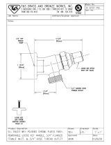
307273 Fluid Outlet Filter, Instructions-Parts List
Fluid Regulators Manuals
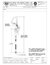
307517 Mastic Fluid Regulators, Instructions-Parts List
308647 Fluid Pressure Regulators, Instructions-Parts List
Pressure Pot Manuals
308369 5-, 10-, and 15-Gallon Pressure Tanks, Instructions-Parts List
Heated Platen Manuals
332511 ExactaBlend AGP Advanced Glazing Proportioner - Heated Platen Kit, Kit Instructions
Reference Manuals
3A1244
Graco Control Architecture
™
Module Programming
Valve Manuals
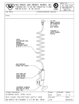
313342 Dosing Valve, Instructions-Parts

Models
4 3A2894F
Models
Base Machines
* An agitator is recommended for urethane applica-
tions utilizing a pressure pot. Set the agitator to
25-50 rpm.
Part No.
Chemical
Industry
Description
Ratio
(by Weight)
Maximum Working Pressure
psi (MPa, bar)
24R809
Silicone
AGP-S100 System, 55 gallon/5 gallon
(200 liter/20 liter) machine with boom
6:1 to 14:1
MD2:
3000 (21, 207)
Ultra-lite with flexible hose mixer:
3000 (21, 207)
Ultra-lite with Tri-core mixer:
4000 (28, 276)
24R810
AGP-S100 System, 55 gallon/5 gallon
(200 liter/20 liter) machine
24R811
Urethane*
AGP-U100 System, 55 gallon/5 gallon
(200 liter/20 liter) machine with boom
24R812
AGP-U100 System, 55 gallon/5 gallon
(200 liter/20 liter) machine
24R813
AGP-U100 System, 55 gallon/5 gallon
(200 liter/20 liter) machine with boom
and pressure pot
24R814
AGP-U100 System, 55 gallon/5 gallon
(200 liter/20 liter) machine with pres-
sure pot
24R815
Polysulfide
AGP-P100 System, 55 gallon/5 gallon
(200 liter/20 liter) machine with boom
24R816
AGP-P100 System, 55 gallon/5 gallon
(200 liter/20 liter) machine

Models
3A2894F 5
Hose Kits
Dispense Valves
Part No.
Hose Kit
Reference
No.
Base Hose
in. (cm)
Catalyst Hose 1
in. (cm)
Catalyst Hose 2
in. (cm)
24R832 #1
5/8 x 120 (1.6 x 305)
1/8 x 60 (0.3 x 152) 1/8 x 60 (0.3 x 152)
24R833 #2 1/4 x 60 (0.6 x 152) 1/8 x 60 (0.3 x 152)
24R834 #3 1/4 x 60 (0.6 x 152) 1/4 x 60 (0.6 x 152)
24T092 #4 3/8 x 60 (1.0 x 152) 1/4 x 60 (0.6 x 152)
24T093 #5 1/8 x 60 (0.3 x 152) 3/32 x 60 (0.2 x 152)
24T094 #6 1/2 x 60 (1.3 x 152) 3/8 x 60 (1.0 x 152)
24U253 #7 3/32 x 60 (0.2 x 152) 3/32 x 60 (0.2 x 152)
Part No. Description
24P217 MD2 dispense valve with handle
24P223 Ultra-lite 6000 with 36 element flexible hose mixer
24P221 Ultra-lite 6000 with 36 element Tri-core mixer

Warnings
6 3A2894F
Warnings
The following warnings are for the setup, use, grounding, maintenance, and repair of this equipment. The exclama-
tion point symbol alerts you to a general warning and the hazard symbols refer to procedure-specific risks. When
these symbols appear in the body of this manual, refer back to these Warnings. Product-specific hazard symbols and
warnings not covered in this section may appear throughout the body of this manual where applicable.
WARNINGWARNINGWARNING
WARNING
ELECTRIC SHOCK HAZARD
This equipment must be grounded. Improper grounding, setup, or usage of the system can cause elec-
tric shock.
• Turn off and disconnect power cord before servicing equipment.
• Connect only to grounded electrical outlets.
• Use only 3-wire extension cords.
• Ensure ground prongs are intact on power and extension cords.
• Do not expose to rain. Store indoors
SKIN INJECTION HAZARD
High-pressure fluid from dispensing device, hose leaks, or ruptured components will pierce skin. This
may look like just a cut, but it is a serious injury that can result in amputation. Get immediate surgical
treatment.
• Do not point dispensing device at anyone or at any part of the body.
• Do not put your hand over the fluid outlet.
• Do not stop or deflect leaks with your hand, body, glove, or rag.
• Follow the Pressure Relief Procedure when you stop dispensing and before cleaning, checking, or
servicing equipment.
• Tighten all fluid connections before operating the equipment.
• Check hoses and couplings daily. Replace worn or damaged parts immediately.
MOVING PARTS HAZARD
Moving parts can pinch, cut or amputate fingers and other body parts.
• Keep clear of moving parts.
• Do not operate equipment with protective guards or covers removed.
• Pressurized equipment can start without warning. Before checking, moving, or servicing equipment,
follow the Pressure Relief Procedure and disconnect all power sources.

Warnings
3A2894F 7
FIRE AND EXPLOSION HAZARD
Flammable fumes, such as solvent and paint fumes, in work area can ignite or explode. To help prevent
fire and explosion:
• Use equipment only in well ventilated area.
• Eliminate all ignition sources; such as pilot lights, cigarettes, portable electric lamps, and plastic drop
cloths (potential static arc).
• Keep work area free of debris, including solvent, rags and gasoline.
• Do not plug or unplug power cords, or turn power or light switches on or off when flammable fumes
are present.
• Ground all equipment in the work area. See Grounding instructions.
• Use only grounded hoses.
• Hold gun firmly to side of grounded pail when triggering into pail. Do not use pail liners unless they
are antistatic or conductive.
• Stop operation immediately if static sparking occurs or you feel a shock. Do not use equipment
until you identify and correct the problem.
• Keep a working fire extinguisher in the work area.
EQUIPMENT MISUSE HAZARD
Misuse can cause death or serious injury.
• Do not operate the unit when fatigued or under the influence of drugs or alcohol.
• Do not exceed the maximum working pressure or temperature rating of the lowest rated system
component. See Technical Data in all equipment manuals.
• Use fluids and solvents that are compatible with equipment wetted parts. See Technical Data in all
equipment manuals. Read fluid and solvent manufacturer’s warnings. For complete information
about your material, request MSDS from distributor or retailer.
• Do not leave the work area while equipment is energized or under pressure.
• Turn off all equipment and follow the Pressure Relief Procedure when equipment is not in use.
• Check equipment daily. Repair or replace worn or damaged parts immediately with genuine manu-
facturer’s replacement parts only.
• Do not alter or modify equipment. Alterations or modifications may void agency approvals and create
safety hazards.
• Make sure all equipment is rated and approved for the environment in which you are using it.
• Use equipment only for its intended purpose. Call your distributor for information.
• Route hoses and cables away from traffic areas, sharp edges, moving parts, and hot surfaces.
• Do not kink or over bend hoses or use hoses to pull equipment.
• Keep children and animals away from work area.
• Comply with all applicable safety regulations.
TOXIC FLUID OR FUMES HAZARD
Toxic fluids or fumes can cause serious injury or death if splashed in the eyes or on skin, inhaled, or
swallowed.
• Read MSDSs to know the specific hazards of the fluids you are using.
• Route exhaust away from work area. If diaphragm ruptures, fluid may be exhausted into the air.
• Store hazardous fluid in approved containers, and dispose of it according to applicable guidelines.
PERSONAL PROTECTIVE EQUIPMENT
Wear appropriate protective equipment when in the work area to help prevent serious injury, including
eye injury, hearing loss, inhalation of toxic fumes, and burns. This protective equipment includes but is
not limited to:
• Protective eyewear, and hearing protection.
• Respirators, protective clothing, and gloves as recommended by the fluid and solvent manufacturer
WARNINGWARNINGWARNING
WARNING

Important Isocyanate (ISO) Information
8 3A2894F
Important Isocyanate (ISO) Information
Isocyanates (ISO) are catalysts used in some two component materials.
Isocyanate Conditions
Material Self-ignition
Keep Components A and B
Separate
PRESSURIZED ALUMINUM PARTS HAZARD
Use of fluids that are incompatible with aluminum in pressurized equipment can cause serious chemical
reaction and equipment rupture. Failure to follow this warning can result in death, serious injury, or prop-
erty damage.
• Do not use 1,1,1-trichloroethane, methylene chloride, other halogenated hydrocarbon solvents or flu-
ids containing such solvents.
• Many other fluids may contain chemicals that can react with aluminum. Contact your material sup-
plier for compatibility.
WARNINGWARNINGWARNING
WARNING
Spraying or dispensing materials containing isocya-
nates creates potentially harmful mists, vapors, and
atomized particulates.
Read material manufacturer’s warnings and material
MSDS to know specific hazards and precautions
related to isocyanates.
Prevent inhalation of isocyanate mists, vapors, and
atomized particulates by providing sufficient ventila-
tion in the work area. If sufficient ventilation is not
available, a supplied-air respirator is required for
everyone in the work area.
To prevent contact with isocyanates, appropriate per-
sonal protective equipment, including chemically
impermeable gloves, boots, aprons, and goggles, is
also required for everyone in the work area.
Some materials may become self-igniting if applied
too thick. Read material manufacturer’s warnings and
material MSDS.
Cross-contamination can result in cured material in
fluid lines which could cause serious injury or damage
equipment. To prevent cross-contamination:
• Never interchange component A and component
B wetted parts.
• Never use solvent on one side if it has been con-
taminated from the other side.

Important Isocyanate (ISO) Information
3A2894F 9
Moisture Sensitivity of
Isocyanates
Exposure to moisture (such as humidity) will cause ISO
to partially cure; forming small, hard, abrasive crystals,
which become suspended in the fluid. Eventually a film
will form on the surface and the ISO will begin to gel,
increasing in viscosity.
NOTE: The amount of film formation and rate of crystal-
lization varies depending on the blend of ISO, the
humidity, and the temperature.
Changing Materials
NOTICE
Partially cured ISO will reduce performance and the
life of all wetted parts.
• Always use a sealed container with a desiccant
dryer in the vent, or a nitrogen atmosphere. Never
store ISO in an open container.
• Keep the ISO pump wet cup or reservoir (if
installed) filled with appropriate lubricant. The
lubricant creates a barrier between the ISO and
the atmosphere.
• Use only moisture-proof hoses compatible with
ISO.
• Never use reclaimed solvents, which may contain
moisture. Always keep solvent containers closed
when not in use.
• Always lubricate threaded parts with an appropri-
ate lubricant when reassembling.
NOTICE
Changing the material types used in your equipment
requires special attention to avoid equipment damage
and downtime.
• When changing materials, flush the equipment
multiple times to ensure it is thoroughly clean.
• Always clean the fluid inlet strainers after flushing.
• Check with your material manufacturer for chemi-
cal compatibility.

Component Identification
10 3A2894F
Component Identification
S100 Models
Key:
A Display Module (DM)
BBoom
C Ram - Base (A) Chemical*
D Ram - Catalyst (B) Chemical*
E Dispense Valve*
F Integrated Air Controls
G Electrical Enclosure
H Flow Meters*
J Fluid Regulator*
K Calibration Check Assembly
L Fluid Control Module (FCM)
M Material Pressure Gauges
N Catalyst (B) Filter
P Fluid Regulator Adjustment
Controls the pressure to the base (A) fluid regulator.
R Pressure Pot (U100 only)*
S Air Motor (U100 only)*
T Displacement Pump (U100 only)*
U Dosing Valve (P100 only)*
* Refer to specific component manual for more detailed
information.
FIG. 1: S100 Models
A
B
C
E
G
F
H
D
F
J
K
L
M
J
M
H
P


Component Identification
3A2894F 13

Component Identification
14 3A2894F
Display Module (DM)
User Interface
Key:
BA System Enable/ Disable
Enables/disables the system. When the system is
disabled, dispense operation is disabled.
BB Soft Keys
Defined by application using the DM.
BC Cancel
Cancel a selection or number entry while in the process of
entering a number or making a selection.
BD Enter
Acknowledge changing a value or making a selection.
BE Lock/Setup
Toggle between run and setup screens. If setup screens
are password protected, button toggles between run and
password entry screen.
BF Field Selection
Navigate to another field when the DM is in setup mode.
These buttons have no function when the DM is in run
mode.
BG Increase / Decrease / Field Selection
Increase or decrease the selected value. Navigate to
another field.
FIG. 4: DM Component Identification - Front
BA
BE
BC
BB
BF
BD
BG

Component Identification
3A2894F 15
BH Model Number
Identification tag for the DM.
BJ CAN Cable Connections
Electrical connection for power and communication to
other GCA devices.
BK Module Status LEDs
Visual indicators to show the status of the DM:
Green Solid - Power provided.
Green Off - No power.
Yellow Flashing - Communication with other GCA
devices occurring.
Red Solid - Bad DM or machine is in critical status
Red Flashing - Wrong program uploaded.
BL Token/Battery Access Cover
Access cover for token and battery.
FIG. 5: DM Component Identification - Rear
BL
BH
BK
BJ

Component Identification
16 3A2894F
Main Display Components
The following figure calls out the navigational, status, and general informational components of each screen.
F
IG. 6: Main Display Components
Current date and time
Current screen
Selection screen
Previous screen
Next screen
Function display
Faults, Status

Component Identification
3A2894F 17
Electrical Enclosure
Key:
DA Power Switch
Turns electrical power on or off.
DB 24VDC Power Supply
Converts input power to 24 VDC.
FIG. 7: Electrical Enclosure
DA
DB

Component Identification
18 3A2894F
Integrated Air Controls
Key:
CA Main Air Slider Valve
Turns air on and off to the entire system. When closed,
the valve relieves pressure downstream.
CB Ram Air Regulator
Controls the ram up and down pressure and blowoff
pressure.
CC Ram Director Valve
Controls the ram direction.
CD Exhaust Port with Muffler
CE Air Motor Regulator
Controls the air pressure to the motor.
CF Air Motor Slider Valve
Turns air on and off to the air motor. When closed, the
valve relieves air trapped between it and the motor. Push
the valve in to shutoff.
CG Blowoff Button
Turns air on and off to push the platen out of an empty
drum.
CJ Catalyst Air Slider Valve
Turns air on and off to the catalyst motor only. When
closed, the valve relieves pressure down stream.
CK Voltage to Pneumatic Regulator (V/P)
Electrically controlled air regulator.
FIG. 8: Integrated Air Controls
CB
CC
CD
CE
CF
CA
CG
Base (A) Side
All Models
Catalyst (B) Side
S100 Models
CB
CC
CD
CG
CJ
CE
CF


Component Identification
20 3A2894F
Fluid Control Module (FCM)
Key:
EA Port 1 - Air Shut off Valve
Controls the air to the base (A) material regulator.
Port 1 - Low Level Sensors (Optional)
Low level input for the both materials. Refer to
Accessories and Kits, page 60, for more details.
Includes splitter.
EB Port 2 - Flow Meters
Base (A) and Catalyst (B) flow meter input. Includes
splitter
EC Port 3 - Solenoid Valve (P100 only)
To open and close the dosing valve.
ED Port 4 - Voltage to Pneumatic (V/P) Regulator
Controls the air to the catalyst (B) material regulator.
EE Port 5 - Audible Light Tower (Optional)
Visual and audible indicator of machine status. Refer to
Accessories and Kits, page 60, for more details.
EF Port 6 - Not Used
EG Port 7 - Not Used
EH CAN Connection
Supplies power and communication to GCA components.
FIG. 10: FCM
EG
EF
EE
EC
EA
EB
ED
EH
/