Page is loading ...

Eyebolts for hoisting screen
(do not lift screen by center of case).
Case support brackets.
Knockouts for electrical connections
(two per end) with plastic plugs*
*Left hand motor location only on Paragon
1
/2" threaded
rod (for suspending
screen) by others.
3
/8" -16 threaded rod
(use for adjusting
deflection in extremely
long units) by others.
8"
13
1
/4"
12"
Please Mark Appropriate Selections
Select Viewing Surface:
Matt White
Glass Beaded
Optional Accessories:
Extra Screen Drop (Total screen height cannot exceed 24')
Same color as viewing surface (standard on AV format screens)
Black (standard on all other formats)
Length of total drop
Black Masking Borders (Optional on AV format, standard on all others)
Wall Mount Bracket Kit (Includes two brackets)
Endcap Ceiling Tile Flange Kit (2 per kit)
Ceiling Tile Flange for front and/or rear of case (12' lengths)
How many 12' lengths do you need?
Control Options:
Please Note: This Draper motorized screen comes with one 110V-120V AC
3-position wall switch (silver wall plate with black rocker)
Total number of 110-120V AC switches (switches operate independently)
Substitute white switch(es) for silver wall plate with black rocker
Serial or Network Communication (Complete Serial & Network Control Planning Sheet)
Optional Low Voltage Control Module (LVC-III)
24 Volt 3-Button Switch Number of 24V switches:
Radio Frequency Remote Control (only with 24v)
Infrared Remote Control (only with 24v)
Optional Key Operated Switch
Power Supply Key Switch (On-off)
3-Position Key Control
3-Position Switch with Hinged Key-Locking Coverplate
Optional Video Interface Control
VIC-115 Override Switch
VIC-12 Override Switch
VIC-6 Override Switch
by
Large Electrically Operated Projection Screen
With Motor–In–Roller
Paragon
Copyright © 2008 Draper Inc. Form Paragon_Sub08-R Printed in U.S.A.
PROJECT:
ARCHITECT:
CONTRACTOR:
SUPPLIER:
DATE: REVISED:
Specifi cations—Paragon
projection screens, size h. x w.,
electrically operated 110-120v AC 60 Hz. 3-wire motor mounted inside
screen roller, 2.5 amp draw, instantly reversible, lifetime lubricated,
with internal thermal overload protector and mechanical brake. Motor
mounted with sound-absorbing fi xtures. Left hand motor location only.
Preset, accessible limit switches. J-box inside case accessible via 22
ga. steel cover plate. Entire roller and drive assembly easily removable
through bottom of case.
Roller to be 6" OD x
1
/8" wall steel tube. Roller brackets to be painted
white and to have double row radial ball bearings. Viewing surface to
be ([GREENGUARD for Children and Schools certifi ed Matt White]
[Glass Beaded]), fl ame and mildew resistant. Matt White and High
Contrast Grey viewing surfaces shall qualify as low emitting and
meet all of the requirements of the GREENGUARD for Children and
Schools and GREENGUARD certifi cation program, which are: emissions of total volatile
organic compounds < 0.22 mg/m
3
, formaldehyde < 0.0135 ppm, total aldehydes < 0.043
ppm, individual volatile organic compounds < 1/1000 TLV and < ½ chronic REL and
total phthalates < 0.01 mg/m
3
. Dowel shall be 1½" OD steel tube with black polyethylene
endcaps.
Case constructed of extruded aluminum. Bottom of case fully enclosed except for slot
allowing fabric passage. Bottom closure panel shall be extruded aluminum, fi nished white,
and may be removed manually for access to roller and drive unit. Closure panel shall be
held in place by screw and bracket at each end of case. Aluminum endplates with integrated
steel brackets for suspended mounting shall be fastened to extruded case with thread-
cutting screws. Eyebolts shall be provided for use in hoisting screen. Case support brackets
shall be welded steel channel, riveted to exterior of case.
Three-position control switch (or switches—specify number) shall stop or reverse screen at
any point. Controls to be furnished complete with cover plate.
Entire unit certifi ed by Underwriters' Laboratories, Inc. for the U.S. and Canada. Suitable
for use in environmental air space in accordance with Section 300-22 (c) of the National
Electrical Code, and Sections 2-128, 12-010 (3) and 12-100 of the Canadian Electrical
Code, Part 1, CSA C22.1. U.S. Patent No. 6,873,461.
Options:
Wall Mount Bracket Kit: Kit includes two structural steel brackets and hardware to attach
brackets to case. Hardware for mounting to wall structure by others.
Endcap Ceiling Tile Flange Kit: Extruded aluminum, fi nished white. Attaches to endcaps.
Each kit contains two (2) fl ange pieces and hardware for attaching trim fl anges to endcaps.
Ceiling Tile Flange for Front of Case: Each kit includes 12' extruded aluminum, fi nished
white. Attaches to front of case. Hardware for attachment to case included.
Downloadable 3-part specifi cations are available at www.draperinc.com.
®
Dimensions & Data
Size Case Net Wt.
H x W Length (Lbs.) Qty.
AV Format
15' x 20' 250" 440
20' x 20' 250" 450
11' x 22' 274" 484
16½' x 22' 274" 494
22' x 22' 274" 504
12' x 24' 298" 528
18' x 24' 298" 538
24' x 24' 298" 548
13' x 26' 322" 572
19½' x 26' 322" 582
14' x 28' 346" 616
21' x 28' 346" 626
Nominal Image Overall Case Net Wt. Qty.
Diagonal Area H x W Size Length (lbs.)
4:3 NTSC Video Format
25' 177" x 236" 182" x 240" 250" 440
27½' 194" x 260" 199" x 264" 274" 484
30' 212" x 284" 217" x 288" 298" 528
32½' 230" x 308" 235" x 312" 322" 572
35' 248" x 332" 253" x 336" 346" 616
16:9 HDTV Video Format
270" 133" x 236" 138" x 240" 250" 440
300" 146" x 260" 151" x 264" 274" 484
324" 160" x 284" 165" x 288" 298" 528
354" 173" x 308" 178" x 312" 322" 572
384" 187" x 332" 192" x 336" 346" 616
Custom Size
Case Dimensions 13¼" high x 12" deep. Optional wall mounting brackets extend
1¾" beyond each end of case (hole centers are 1" from end of case).
Please see back page for dimensional diagrams of case and
optional wall mounting bracket
Part of the Draper
EcoVision™ range
of products
EcoVision
Paragons with cases longer than 300" require special handling.
(VICs are compatible only with the
Override Switch, and not with any
other wall switches or controls)

Paragon by Draper Page 2 of 2
Single Station Control
Internal Screen Wiring
White (Common)
Black (Down)
Red (Up)
Green (Ground)
Dashed wiring
by electrician
Control
switch
Single gang box by others
Min. 4" x 2
1
/
8
" x 1
7
/
8
" deep
Red
Black
Blue
Location of key
operated on-off
switch if furnished
To 110-120V Line
Multiple Station Control
Internal Screen Wiring
White (Common)
Black (Down)
Red (Up)
Green (Ground)
Dashed wiring
by electrician
Red
Red
Black
Blue
Blue
Cap off with wire
nut and tape
Black
Red
Blue
Black
Single gang box by others
Min. 4" x 2
1
/
8
" x 1
7
/
8
" deep.
3 shown. More or less equally
feasible.
Location of key
operated on-off
switch if furnished
To 110-120V Line
Wiring Diagrams
Case Dimensions*
12"
13
1
/4"
5"
8"
2"
1
3
/8"
*
* - Case support brackets will be evenly spaced along the case
2" 2"
2¼"
2¼"
3
1
/
4
"
3
1
/
4
"
2
7
/
8
"
1"
3
/
8
" dia.
1
/
2
" dia.
2
7
/
8
"
2
7
/
8
"
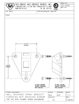
Optional Wall Mounting Bracket
*Please Note: Optional wall brackets add 1¾" per bracket to case length. Wall mounting bracket hole location is 1" from end of case.
www.draperinc.com
(765) 987-799
9
Low Voltage, IR Remote or RF Remote (LVC-III)
* For more information and wiring diagrams for low voltage
multiple motors and network communication, please see
Draper Screen and Lift Controls Planning Sheet, Draper
Screens and Lift Controls Wiring Manual and wiring
diagrams supplied with individual items.
3 Button Wall Switch
DOWN - Black
COM - White
UP - Red
White-Common to screen & 110-120V AC Neutral
Red-to screen (directional)
Brown-to screen (directional)
Yellow-to 110-120V AC-Hot
Black-to 110-120V AC-Hot
Green-Ground
Eye Port for IR Eye, RF Receiver or LED
Wall Switch. For more than one of
these, a splitter is required.
Aux Port for connecting additional LVC-III
modules (up to six total can be linked-
connect from Aux to Eye).
Dashed wiring by electrician
Low voltage wiring by others
White (Common)
Red (Up)
Black (Down)
Green (Ground)
Location of key
operated on-off
switch if furnished
To
110-120V
Line
Internal Screen Wiring
STOP
Control
Switches
24v DC
STOP
PROJECT:
SUPPLIER:
DATE: REVISED:
/

