Polk Audio AMR130 User manual
- Category
- Loudspeakers
- Type
- User manual
This manual is also suitable for

OWNER’S
MANUAL
AMR130
5.1 COMPUTER SPEAKER SYSTEM


For accessories and information visit www.polkaudio.com 1
NOTE TO CATV SYSTEM INSTALLER:
This reminder is provided to call the CATV (Cable-TV) system installer’s attention to Article
820-40 of the NEC, that provides guidelines for proper grounding and, in particular, specified
that the cable ground shall be connected to the grounding system of the building, as close to
the point of cable entry as practical.
NOTE:
This equipment has been tested and found to comply with the limits for a Class B digital device,
pursuant to Part 15 of the FCC Rules. These limits are designed to provide reasonable
protection against harmful interference in a residential installation. This equipment generates,
uses and can radiate radio frequency energy and, if not installed and used in accordance with
the instructions, may cause harmful interference to radio communications. However, there is
no guarantee that interference will not occur in a particular installation.
If this equipment does cause harmful interference to radio or television reception, which can be
determined by tuning the equipment off and on, the user is encouraged to try to correct the
interference by one or more of the following measures:
• Reorient or relocate the receiving antenna.
• Increase the separation between the equipment and receiver.
• Connect the equipment into an outlet on a circuit different from that to which the
receiver is connected.
• Consult the dealer or an experienced radio/TV technician for help.
NOTE:
Changes or modifications may cause this unit to fail to comply with Part 15 of the FCC Rules
and may void the user’s authority to operate the equipment.
IMPORTANT SAFETY INSTRUCTIONS
READ BEFORE OPERATING EQUIPMENT
These products were designed and manufactured to meet strict quality and safety standards. There
are, however, some installation and operation precautions which you should be particularly aware of.
1. Read Instructions—All the safety and operating instructions should be read before the
system is operated.
2. Retain Instructions—The safety and operating instructions should be retained for future reference.
3. Heed Warnings—All warnings on the appliances and in the operating instructions should be adhered to.
4. Follow Instructions—All operating and use instructions should be followed.
5. Cleaning—Unplug the appliances from wall outlets before cleaning. Do not use liquid cleaners or
aerosol cleaners. Use a damp cloth for cleaning.
6. Attachments—Do not use attachments not recommended by the product manufacturer as they
may cause hazards.
7. Water and Moisture—Do not use these appliances near water-for example, near a bath tub, wash
bowl, kitchen sink, or laundry tub, in a wet basement, or near a swimming pool, and the like.
8. Accessories—Do not place these appliances on an unstable cart, stand, tripod, bracket, or table.
The audio/video products may fall, causing serious injury to a child or adult, and serious damage to
the products. Use only with a cart, stand, tripod, bracket, or table recommended by the manufacturer,
or sold with the appliances. Any mounting of the appliances should follow the manufacturer’s
instructions, and should use mounting accessories recommended by the manufacturer.
9. Ventilation—Slots and openings in the cabinet are provided for ventilation and to ensure reliable
operation of the appliances and to protect them from overheating, and these openings must not be
blocked or covered. The openings should never be blocked by placing the products on a bed, sofa,
rug, or other similar surface. These products should never be placed near or over a radiator or heat
register. These products should not be placed in a built-in installation such as a bookcase or rack
unless proper ventilation is provided or the manufacturer’s instructions have been adhered to.
10. Power Sources—These products should be operated only from the type of power source
indicated on the marking labels. If you are not sure of the type of power supply to your home, consult
your appliance dealer or local power company. For video products intended to operate from battery
power, or other sources, refer to the operating instructions.
11. Grounding or Polarization—These products are equipped with polarized alternating-current line
plugs (plugs having one blade wider than the other). This plug will fit into the power outlet only one
way. This is a safety feature. If you are unable to insert the plug fully into the outlet, try reversing the
plug. If the plug should still fail to fit, contact your electrician to replace your obsolete outlet. Do not
defeat the safety purpose of the polarized plug.
12. Power-Cord Protection—Power-supply cords
should be routed so that they are not likely to be
walked on or pinched by items placed upon or
against them, paying particular attention to cords at
plugs, convenience receptacles, and the point where
they exit from the appliances.
13. Outdoor Antenna Grounding—If an outside
antenna or cable system is connected to the
product, be sure the antenna or cable system is
grounded so as to provide some protection against voltage surges and built up static charges.
Section 810 of the National Electrical Code, ANSI/NFPA No. 70-1984, provides information with
respect to proper grounding of the mast and supporting structure, grounding of the lead-in wire to an
antenna discharge unit, size of grounding conductors, location of antenna-discharge unit, connection
to grounding electrodes, and requirements for the grounding electrode.
14. Lightning—For added protection for these audio/video products during a lightning storm, or
when they are left un-attended and unused for long periods of time, unplug them from the wall outlet
and disconnect the antenna or cable system. This will prevent damage to the products due to
lightning and power-line surges.
15. Power Lines—An outside antenna system should not be located in the vicinity of overhead power
lines or other electric light or power circuits, or where it can fall into such power lines or circuits.
When installing an outside antenna system, extreme care should be taken to keep from touching
such power lines or circuits as contact with them might be fatal.
16. Overloading—Do not overload wall outlets and extension cords as this can result in a risk of fire
or electric shock.
17. Object and Liquid Entry—Never push objects of any kind into these products through openings
as they may touch dangerous voltage points or short-out parts that could result in a fire or electric
shock. Never spill liquid of any kind on these audio/video products.
18. Servicing—Do not attempt to service these products yourself as opening or removing
covers may expose you to dangerous voltage or other hazards. Refer all servicing to qualified
service personnel.
19. Damage Requiring Service—Unplug these products from wall outlets and refer servicing to
qualified service personnel under the following conditions:
a. When the power-supply cord or plug is damaged.
b. If liquid has been spilled, or objects have fallen into the products
c. If the products have been exposed to rain or water.
d. If the products do not operate normally by following the operating instructions. Adjust only those
controls that are covered by the operating instructions as an improper adjustment of other controls
may result in damage and will often require extensive work by a qualified technician to restore the
product to its normal operation.
e. If the product has been dropped or the cabinet has been damaged.
f. When the product exhibits a distinct change in performance-this indicates a need for service.
20. Replacement Parts—When replacement parts are required, be sure the service technician has
used replacement parts specified by the manufacturer or have the same characteristics as the
original part. Unauthorized substitutions may result in fire, electric shock or other hazards.
21. Safety Check—Upon completion of any service or repairs to these products, ask the service
technician to perform safety checks to determine that the products are in proper operating condition.
22. Carts and Stands—The appliances should be used only with a cart or stand that is
recommended by the manufacturer.
23. An appliance and cart combination should be moved with care. Quick stops, excessive force, and
uneven surfaces may cause the appliance and cart combination to overturn.
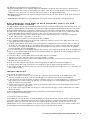
See Figure 1.
GROUND
CLAMP
ELECTRIC
SERVICE
EQUIPMENT
POWER SERVICE GROUNDING
ELECTRODE SYSTEM
(NEC ART 250, PART H)
EXAMPLE OF ANTENNA GROUNDING
ACCORDING TO NATIONAL ELECTRICAL
CODE INSTRUCTIONS CONTAINED IN
ARTICLE 810 -“RADIO AND TELEVISION EQUIPMENT”
ANTENNA
LEAD IN
WIRE
ANTENNA
DISCHARGE UNIT
(NEC SECTION 810-20)
GROUNDING CONDUCTORS
(NEC SECTION 810-21)
GROUND CLAMPS
NEC - NATIONAL ELECTRICAL CODE
Figure 1.
“ ”

2 Contact Polk Audio Customer Service 1-800-377-7655, [email protected]
GETTING STARTED
The AMR130 Speaker System carton contains the following items:
"
Four (4) Magnetically Shielded Satellite Speakers
"
One (1) Set of Front/Rear (green/black) Connectors
"
One (1) Magnetically Shielded Center Channel Speaker
"
One (1) Center/Subwoofer (yellow) Connector
"
One (1) Magnetically Shielded Powered Subwoofer
"
One (1) Outboard AC Power Supply
"
Two (2) Satellite Wall Mounting Brackets
"
Two (2) Adhesive Rubber Pads
"
One (1) Center Channel Wall Mounting Template
"
Two (2) Double-Stick Pads
Please inspect each loudspeaker carefully. Notify your Polk Audio dealer if you notice any difference, damage, or any missing items. Keep the
carton and packing material. They will do the best job of protecting your speakers if they need to be transported.
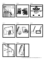
SETUP 1
5.1 SOUNDCARDS INCLUDING SOUNDBLASTER LIVE, TURTLE BEACH & PHILLIPS PSC706 SOUNDCARDS (Figures 1a & 1b)
For 5.1 mode. Consult your soundcard’s user manual or “Help” function for information about configuring the soundcard software.
SETUP 2
OLDER, NON-5.1 SOUNDCARDS
How To Get Bass With No Subwoofer Input: When using an older, non-5.1 soundcard, you will not be using the AMR130’s “Center/Subwoofer In”
jack. But fear not! You will still get low frequency response from the AMR130 System. How? The “Center/Subwoofer In” jack is a switch; when
there is no “Center/Subwoofer In” connection, the AMR130 System functions as a 2.1 or 4.1 system (depending upon whether you have a 2
channel or 4 channel soundcard). The amplifier’s low pass filter automatically switches from the “Center/Subwoofer In” jack to the “Front In”
jack when the system senses no “Center/Subwoofer” input. Be aware that the Center Channel does not function in 2.1 or 4.1 systems. (For that,
you need to upgrade your soundcard to 5.1.)
FOR SINGLE-LINE OUT, STEREO/2-CHANNEL SOUNDCARDS (Figure 2)
For 2.1 mode (no Center Channel function).
FOR DUAL-LINE OUT, 4-CHANNEL SOUNDCARDS (Figure 3)
For 4.1 mode (no Center Channel function).
Consult your soundcard’s user manual or “Help” function for information about configuring the soundcard software.
CONNECTING YOUR AMR130 SPEAKERS [FIGURES 4 & 5]
Four of the five AMR130 Satellite Speakers are hardwired with speaker wire. The front right Satellite is hardwired with a multi-pin DIN connec-
tor. Connect the speakers as shown using push tab connectors (figure 5). Note that one of the wire strands is marked with a red indicator at the
end and the other is unmarked. Make certain that you connect the red marked wire to the red (+) terminal on the amplifier and the unmarked
strand to the black (-) terminal on the amplifier.
VOLUME AND BLENDING CONTROLS
"
Turn the system ON by pushing the MASTER POWER switch on the Subwoofer. The LED will glow green.
"
Turn the ON/OFF-VOLUME knob (on the right “Master” Satellite) clockwise to ON. The LED on the Satellite will glow green.
"
Put on a multi-channel source (game or DVD) and set the Satellite’s VOLUME knob to a comfortable listening level.
"
Set the FRONT/REAR BALANCE with the FADER knob (located behind the VOLUME control on the right Satellite speaker). Most 5.1
Soundcard software will have balance tests and separate channel test tones, much like a 5.1 home theater receiver. Refer to your soundcard’s
user manual or “Help” function to use these tests to help set balance and fader levels. For more on setting controls, visit
http://www.polkaudio.com/multimedia/faqad/.
"
Next, set Bass VOLUME to taste using the SUBWOOFER VOLUME knob. Adjust for good blending between the Satellites and the Subwoofer.
Select the setting for the perfect amount of bass for your taste.
"
Once SUBWOOFER VOLUME is set, use the VOLUME control on the Satellite to adjust overall system volume.
"
Use either the Satellite OR Subwoofer ON/OFF switch to turn the system on and off.
SPEAKER PLACEMENT [FIGURE 6]
All AMR130 speakers are magnetically shielded for safe placement on your desk near your computer monitor or video display. If you notice
video distortion or discoloration, immediately move the speaker away from the monitor and call Polk Audio Customer Service 800-377-7655 (US
& Can), 410-764-5266, 9am-6pm EST, Monday through Friday, or email: [email protected].

For accessories and information visit www.polkaudio.com 3
Your AMR130 Center Channel Speaker can be mounted three ways:
1. On top of your video monitor. Use the adjustable sliding Easel Stand [figure 7] on the back of the Center Speaker to compensate for the
shape of your monitor. Depress the lever on the sliding easel to aim the speaker driver toward your listening position. If your monitor has a
small flat area on top and you want to to adhere the speaker to the monitor, use the supplied double-stick pads.
2. Directly below your monitor. Remove the adjustable sliding Easel Stand on the back of the Center Speaker to aim the speaker driver toward
your listening position.
3. On the wall above your monitor. Use the two built-in keyhole slots on the back of the Center Speaker to wall mount the speaker.
WALL-MOUNTING YOUR AMR130 REAR SURROUND SATELLITES AND
CENTER CHANNEL SPEAKER
Your AMR130 Satellites come with snap-on wall mounting brackets for the two rear surround satellite speakers. The bracket snaps directly on to
the speaker as shown in [figure 8]. Use the bracket itself as the location template for wall mounting the Satellite speaker. The Center Channel
Speaker has built-in keyhole brackets, and a template is included for locating your installation. On-wall installation of AMR speakers requires
basic skills and basic tools (drill and screwdriver). If you are in doubt that you possess the necessary skills or tools, consult your Polk dealer
or a professional installer. Otherwise, follow the steps below to safely secure the speakers to the location of your choice.
"
Make sure the material on which you plan to mount the speakers (plaster, drywall, paneling, stone, etc.) can support the weight of the
speakers (AMR130 Satellites = approximately 12 lbs/0.7 kg ea).
"
Make sure the locations you select do not conceal electrical wiring or plumbing.
"
Prior to installation, hold the speaker in the chosen location to make sure it safely clears obstacles such as ceiling, adjacent walls, corners,
beams, lighting fixtures and door/window frames.
"
For Satellite speakers: Hold the bracket for the speaker you are planning to wall mount up to your chosen location (before you snap it onto
the speaker). For Center Channel Speaker: use the mounting template (included). Be sure to orient it so that the small ends of the keyhole
slots are facing “up” according to the direction of installation. Using the keyhole slots in the bracket as a template, mark the installation
location of the keyhole slots with a pencil [figure 9].
"
If you are certain that there is a stud behind the wall surface, drive #10 screws (not included) through the wall and into the stud [figure 10a].
"
If there is no stud behind the wall at the chosen location, install #10 wall anchors (not supplied) into the wall by following the wall-anchor-
manufacturer’s instructions [figure 10b].
"
For masonry walls, use a masonry drill bit and #10 masonry anchor and screw (not included).
"
Tighten screws into stud or wall anchors, leaving screw heads protruding x" (4.8mm).
"
Snap the bracket onto the back of the speaker as shown in [figure 8]. Line up the keyhole slots on the bracket so that the screw heads pass
through the large center hole of the slots.
"
Let the speaker slide straight down, allowing the screw head to slip behind the smaller end of the keyhole slot [figure 11].
"
Tug gently on the speaker to make certain that the screws and bracket are properly aligned and that the wall anchors are secure.
"
If the bracket is not held snug against the wall by the screw heads, remove the speaker from the wall, drive the screws in a little further and
then remount the speaker.
TROUBLESHOOTING
WEAK SOUND, NO SOUND, BAD SOUND?
"
Make sure the AC adapter is connected to a live AC outlet and is connected to the Subwoofer. Make sure the POWER switches on the
Subwoofer and Satellite are in the ON position. The green LED lights on the Satellite and Subwoofer units should BOTH be lit.
"
Is there output from your soundcard? Connect the speakers to an alternate audio source, such as the headphone jack of a CD player or radio.
If the speakers produce sound the problem is probably with your soundcard. Recheck your soundcard installation and setup procedure.
Consult the soundcard’s instruction manual.
"
Check the software-based “mute” and “volume” controls on your soundcard or media player software and the hardware-based controls on
your keyboard or computer or “Help” function.
"
Are the speakers connected properly? Make sure the plugs are securely connected in the proper locations according to their color-coding as
shown in this manual.
For more detailed Multimedia troubleshooting info than you bargained for, visit the Troubleshooting Guide at
http://www.polkaudio.com/multimedia/faqad/.
TECHNICAL ASSISTANCE OR SERVICE
If, after following these hook up directions, you experience difficulty, please double-check all wire connections. Should you isolate the problem
to the speaker, contact the authorized Polk Audio dealer where you made your purchase, or call Polk Audio’s friendly Customer Service
Department at 800-377-7655 (US or CAN), 410-764-5266 (9am to 6pm EST, Monday through Friday). You may also contact us via email:
[email protected]. Log on to www.polkaudio.com to register your new speakers (and write your own review of them!); join Club Polk; get
on the mailing list for the Polk Audio FREE quarterly Newspaper, and pick up some nifty logowear and stuff.

4 Contact Polk Audio Customer Service 1-800-377-7655, [email protected]
Figure 1a
5.1 Soundcards including
Soundblaster Live and
Turtle Beach.
Yellow
Green
Black
Left
Rear
Right
Rear
Center
Left
Front
Right Front
DIN
Center/Sub In
(Yellow)
Rear In (Black)
Front In (Green)
12VAC
4.5A
Figure 1b
5.1 Philips PSC706 Soundcard
Green
Left
Rear
Center
Left
Front
Right Front
DIN
Center/Sub In
(Yellow)
Rear In (Black)
Front In (Green)
Adapter cable
included with
Philips sound card
Black
Black
Green
Green
Yellow
Yellow
12VAC
4.5A
Right
Rear
Figure 2
Single-line out, stereo/
2-channel soundcards.
Left
Rear
Center
Left
Front
Right Front
DIN
Center/Sub In
(Yellow)
Green
Rear In (Black)
Front In (Green)
Right
Rear
Use "Y" Cable
(3.5mm to 3.5mm)
or
Single Front In
For Stereo Play
12VAC
4.5A
Figure 3
Dual-line out, 4-channel
soundcards
Green
Black
Left
Rear
Center
Left
Front
Right Front
DIN
Center/Sub In
(Yellow)
Rear In (Black)
Front In (Green)
Right
Rear
12VAC
4.5A

For accessories and information visit www.polkaudio.com 5
Figure 4
Right
Rear
Left
Rear
Center
Left
Front
Right Front
DIN
Red indicator is on the tips of the
positive wires. These connect
to the red (+) speaker terminals.
Figure 5
Figure 6
Figure 7 Figure 8
Figure 9
Figure 10
a
b
Figure11
Depress lever
to adjust

POLK AUDIO LIMITED WARRANTY
Polk Audio, Inc. warrants to the original purchaser only that this Polk Audio Loudspeaker Product (the “Product”) will be free from defects in materials and work-
manship for a period of one (1) year from the date of original retail purchase from a Polk Audio Authorized Dealer. However, this Warranty will automatically
terminate prior to the expiration of the one (1) year if the original retail purchaser sells or otherwise transfers the Product to any other party. The original retail
purchaser shall hereinafter be referred to as “you.” To allow Polk Audio to offer the best possible warranty service, please fill out the Product Registration
Card(s) and send it to the Factory, at the address provided on the Product Cards(s) within ten (10) days of the date of purchase.
Defective Products must be shipped, together with proof of purchase, prepaid insured to the Polk Audio Authorized Dealer from whom you purchased the
Product, or to the Factory at 2550 Britannia Boulevard, Suite D, San Diego, California 92154. Products must be shipped in the original shipping container or
its equivalent; in any case the risk of loss or damage in transit is to be borne by you.
If upon examination at the Factory or Polk Audio Authorized Dealer it is determined that the unit was defective in materials or workmanship at any time during
this Warranty period, Polk Audio or the Polk Audio Authorized Dealer will, at its option, repair or replace this Product at no additional charge, except as set
forth below. All replaced parts and Products become the property of Polk Audio. Products replaced or repaired under this
warranty will be returned to you, within a reasonable time, freight prepaid.
This warranty does not include service or parts to repair damage caused by accident, disaster, misuse, abuse, negligence, inadequate packing or shipping pro-
cedures, commercial use, voltage inputs in excess of the rated maximum of the unit, cosmetic appearance of cabinetry not directly attributable to defect in mate-
rials or workmanship, or service, repair, or modification of the Product which has not been authorized or approved by Polk Audio. This warranty shall terminate
if the Serial number on the Product has been removed, tampered with or defaced.
This warranty is in lieu of all other expressed Warranties. If this Product is defective in materials or workmanship as warranted above, your sole remedy shall be
repair or replacement as provided above. In no event will Polk Audio, Inc. be liable to you for any incidental or consequential damages arising out of the use
or inability to use the Product, even if Polk Audio, Inc. or a Polk Audio Authorized Dealer has been advised of the possibility
of such damages, or for any claim by any other party. Some states do not allow the exclusion or limitation of consequential damages, so the above
limitation and exclusion may not apply to you.
All implied warranties on this Product are limited to the duration of this expressed Warranty. Some states do not allow limitation on how long an implied
Warranty lasts, so the above limitations may not apply to you. This Warranty gives you specific legal rights, and you also may have other rights which vary
from state to state.
This Warranty applies only to Products purchased in the United States of America, its possessions, and U.S. and NATO armed forces exchanges and audio clubs.
The Warranty terms and conditions applicable to Products purchased in other countries are available from the Polk Audio Authorized Distributors in such countries.
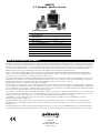
Product Specifications
Frequency Response 37 Hz - 21 kHz
Input sensitivity for
maximum output 0.05 (volts)
S/N Ratio >90 dB
Max SPL @ 0.5 m 106 dB
Surround Satellite Dimensions 7”H x 5x”W x 34”D
Center Channel Dimensions 44”H x 74”W x 3”D
Subwoofer Dimensions 8z”H x 64”W x 134”D
Satellite Drivers 3” Full Range Driver
Center Channel Driver 3” Full Range Driver
Long-Throw Subwoofer 54”
Total System Power 40 Watts RMS (80 Watts Peak)
AMR130
5.1 Computer Speaker System
Polk Audio
5601 Metro Drive
Baltimore, Maryland 21215
(800) 377-7655
-
 1
1
-
 2
2
-
 3
3
-
 4
4
-
 5
5
-
 6
6
-
 7
7
-
 8
8


Polk Audio AMR130 User manual
- Category
- Loudspeakers
- Type
- User manual
- This manual is also suitable for
Ask a question and I''ll find the answer in the document
Finding information in a document is now easier with AI
Related papers
-
Polk Audio AMR150 User manual
-
-
-
-
polkaudio PSW 15TM User manual
-
-
-
-
-
